1
Thank You for purchasing this
Factory Service Manual on EBAY
from PCTECHINFO!
Click Here for more Factory Service
Manuals for other Computer and
Printer / Copier Manufacturers
from PCTECHINFO!
OKIOFFICE 44
Service Manual
59276801
All specifications are subject to change without notice.
Disclaimer
This document may not be reproduced without the written permission of OKIDATA Training and
Publications. Evert effort has been made to ensure the accuracy of the information contained in this
training course. OKIDATA is not responsible for errors beyond its control.
Copyright / About Information
Copyright 1997 by OKIDATA. All rights reserved.
First Release P/N 59276801
September, 1997
Written by OKIDATA Training and Publications
Contact Information
Please address any comments on this publication to:
Mailing Address
OKIDATA
532 Fellowship Road
Mount Laurel, NJ 08054-3499
Web Site
Telephone
Facsimile
OKILINK Login Name
www.OKIDATA.com
(609) 235-2600
(609) 222-5320
Technical Training
Copyright Listing
OKIDATA is a registered trademark of Oki Electric Industry Company, Ltd.; marques deposee de Oki
Electric Industry Company, Ltd.; marca registrada, Oki Electric Industry Company, Ltd.
Faxable Facts is a trademark, All Rights Reserved, 1993
IBM, PC, PC-DOS, and Proprinter XL are registered trademarks of International Business Machines
Corporation.
Microsoft and MS-DOS are registered trademarks and Microsoft Basic, Windows, TrueImage, and
TrueType are trademarks of Microsoft Corporation.
OKILINK II is a trademark of Oki Electric Industry Company, Ltd.
ZIP Code is a registered trademark of the United States Postal Service
Contents
Section 1: General Information ............................................................... 1 - 1
1.1
1.2
1.3
1.4
1.5
1.6
General Performance ........................................................................................................... 1 - 1
General User's Function ...................................................................................................... 1 - 4
General Maintenance Functions .......................................................................................... 1 - 7
General Appearance ............................................................................................................. 1 - 8
Basic Performance Specifications ....................................................................................... 1 - 9
Reports and Lists ............................................................................................................... 1 - 20
Section 2: Installation .............................................................................. 2 - 1
2.1
2.2
2.3
2.4
2.5
2.6
2.7
2.8
2.9
General Setup Information .................................................................................................. 2 - 1
Site Selection ....................................................................................................................... 2 - 3
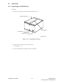
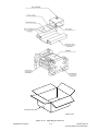
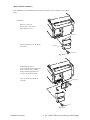
Unpacking ............................................................................................................................ 2 - 4
2.3.1 Unpacking for OKIOFFICE 44 ............................................................................... 2 - 4
Check of Contents ............................................................................................................... 2 - 6
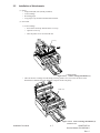
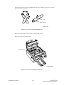
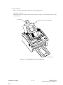
Installation of Attachments .................................................................................................. 2 - 7
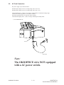
AC Cord Connection ......................................................................................................... 2 - 12
Telephone and Line Connections ...................................................................................... 2 - 13
Packing for Shipment ........................................................................................................ 2 - 13
Initial Settings .................................................................................................................... 2 - 14
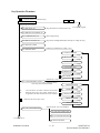
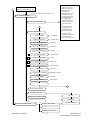
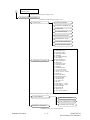
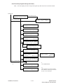
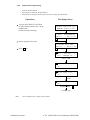
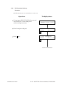
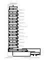
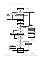
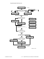
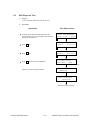
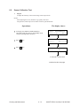
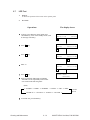
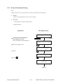
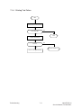
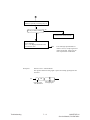
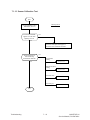
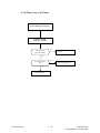
2.9.1 General Procedure of Key Operation .................................................................... 2 - 14
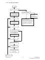
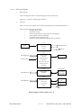
Key Operation Flowchart ...................................................................................... 2 - 15
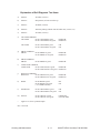
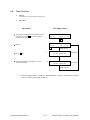
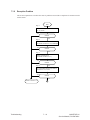
2.9.2 Technical Functions ............................................................................................... 2 - 18
Service Personnel Initial Settings Table 2.9.1 (1/7) .............................................. 2 - 19
Service Personnel Initial Settings Table 2.9.1 (2/7) .............................................. 2 - 20
Service Personnel Initial Settings Table 2.9.1 (3/7) .............................................. 2 - 21
Service Personnel Initial Settings Table 2.9.1 (4/7) .............................................. 2 - 22
Service Personnel Initial Settings Table 2.9.1 (5/7) .............................................. 2 - 23
Service Personnel Initial Settings Table 2.9.1 (6/7) .............................................. 2 - 24
Service Personnel Initial Settings Table 2.9.1 (7/7) .............................................. 2 - 25
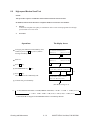
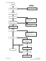
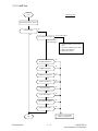
TEL/FAX Automatic Switching ............................................................................ 2 - 26
TEL/FAX Mode Flow Chart .................................................................................. 2 - 27
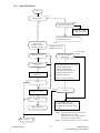
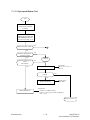
TAD Mode Flow Chart (Type 1) ........................................................................... 2 - 28
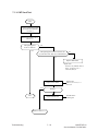
TAD Mode Flow Chart (Type 2) ........................................................................... 2 - 29
2.9.3 Technical Functions Example ................................................................................ 2 - 30
Technical Functions 01 to 11 (Table 2.9.2, 1/5) .................................................... 2 - 32
Technical Functions 12 to 16 (Table 2.9.2, 2/5) .................................................... 2 - 33
Technical Functions 17 to 23 (Table 2.9.2, 3/5) .................................................... 2 - 34
Technical Functions 24 to 27 (Table 2.9.2, 4/5) .................................................... 2 - 35
Technical Functions 28 to 31 (Table 2.9.2, 5/5) .................................................... 2 - 36
Table of Contents
TOC - 1
OKIOFFICE 44
Service Manual, P/N 59276801
2.9.4
User’s Functions .................................................................................................... 2 - 37
User's Functions..................................................................................................... 2 - 38
Feature Specifications Table 2.9.3 (1/3) ................................................................ 2 - 38
Feature Specifications Table 2.9.3 (2/3) ................................................................ 2 - 39
Feature Specifications Table 2.9.3 (3/3) ................................................................ 2 - 40
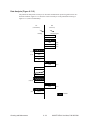
One-Touch Key Program Settings (Flowchart) ..................................................... 2 - 41
One-Touch Key Program Settings [Table 2.9.4} (1/4) .......................................... 2 - 42
One-Touch Key Program Settings Table [2.9.4] (2/4) ........................................... 2 - 43
One-Touch Key Program Settings [Table 2.9.4] (3/4) ........................................... 2 - 44
One-Touch Key Program Settings [Table 2.9.4] (4/4) ........................................... 2 - 45
User Function Program Settings Table 2.9.4 (1/4) ................................................ 2 - 46
Function Program .................................................................................................. 2 - 46
User Function Program Settings Table 2.9.4 (2/4) ................................................ 2 - 47
User Function Program Settings Table 2.9.4 (3/4) ................................................ 2 - 48
User Function Program Settings Table 2.9.4 (4/4) ................................................ 2 - 49
2.9.5 User's Functions Example ..................................................................................... 2 - 50
Function Program .................................................................................................. 2 - 50
User's Functions Table 2.9.5 (1/2) ........................................................................ 2 - 51
User's Functions Table 2.9.5 (2/2) ........................................................................ 2 - 52
Ring Response Time .............................................................................................. 2 - 54
Dial Parameters (Service Bit "OFF") ................................................................... 2 - 55
2.9.6 Clock Adjustment .................................................................................................. 2 - 56
2.9.7 Dual Access Operation .......................................................................................... 2 - 57
2.9.8 System Data Programming .................................................................................... 2 - 58
2.9.9 Dial Parameters Settings ........................................................................................ 2 - 60
Procedure ............................................................................................................... 2 - 60
Dial Parameters Settings (Table 2.9.6) .................................................................. 2 - 62
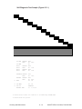
2.9.10 Off-line Tests ......................................................................................................... 2 - 63
Purpose ................................................................................................................ 2 - 63
Procedure ............................................................................................................... 2 - 63
Self-Diagnosis Print Test (Example) Figure 2.9.4 ................................................. 2 - 64
2.9.11 On-line Tests .......................................................................................................... 2 - 65
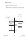
Transmission .......................................................................................................... 2 - 65
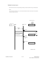
Reception ............................................................................................................... 2 - 65
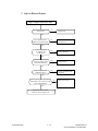
Typical Transmission Flow (Fig. 2.9.5) ................................................................ 2 - 66
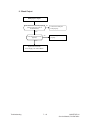
Typical Reception Flow (Fig. 2.9.6) ...................................................................... 2 - 67
2.9.12 Installation of Optional Units ................................................................................ 2 - 68
Items
................................................................................................................ 2 - 68
Procedure ............................................................................................................... 2 - 68
Memory Board Installation .................................................................................... 2 - 69
CTR (PC interface) Board Installation .................................................................. 2 - 70
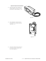
Optional Telephone Set Installation....................................................................... 2 - 71
Table of Contents
TOC - 2
OKIOFFICE 44
Service Manual, P/N 59276801
Section 3: Brief Technical Description ................................................... 3 - 1
Electrophotographic Process Flow .................................................................................................. 3 - 1
3.1
Fundamentals of the Electro-Photographic Process ............................................................ 3 - 2
3.2
Actual Electrophotographic Process .................................................................................... 3 - 5
3.3
Boards and Units ................................................................................................................. 3 - 6
Block Diagram (Figure 3.3.1).............................................................................................. 3 - 7
3.4
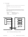
Overall Dimension and Mechanical Structure..................................................................... 3 - 8
Section 4: Disassembly ........................................................................... 4 - 1
4.1
General................................................................................................................................. 4 - 1
4.1.1 Precautions for Parts Replacement .......................................................................... 4 - 1
Service Caution ....................................................................................................... 4 - 2
4.1.2 Tools ........................................................................................................................ 4 - 3
4.1.3 How to Disassemble and Reassemble ..................................................................... 4 - 3
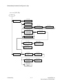
Disassembly Procedure Flow Figure 4.1 (1/2) ........................................................ 4 - 4
Disassembly Procedure Flow Figure 4.1 (2/2) ........................................................ 4 - 5
Whole Unit Picture .................................................................................................. 4 - 6
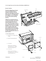
4.1.3.1 LED Print Head ........................................................................................ 4 - 7
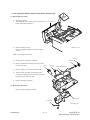
4.1.3.2 Image Drum and Covers (Rear, NCU, Main) and NCU Board ................ 4 - 8
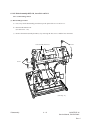
4.1.3.3 Unit-048 OPE-Panel ............................................................................... 4 - 10
4.1.3.4 Separation Rubber, Sensor Frame Roller Assembly (U) ........................ 4 - 11
4.1.3.5 Roller Assembly-ADF, CIS, Lever-PC1 and PC2 .................................. 4 - 12
4.1.3.6 Board-R44, OKIOFFICE 44 Power Supply Unit ................................... 4 - 14
4.1.3.7 Option (Board-Memory: MEM, Board-CTR; PC Interface) .................. 4 - 16
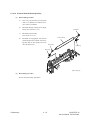
4.1.3.8 Printer Unit Section ................................................................................ 4 - 17
4.1.3.9 Transfer Roller ........................................................................................ 4 - 18
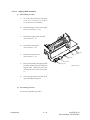
4.1.3.10 High-Voltage Power Supply Unit (TLHV/OLHV) ................................ 4 - 19
4.1.3.11 Holder Assembly .................................................................................... 4 - 20
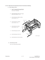
4.1.3.12 Plate-Side M and Gear-Idle .................................................................... 4 - 21
4.1.3.13 Registration Roller .................................................................................. 4 - 22
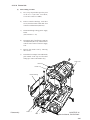
4.1.3.14 Drive Shaft E (Eject) and Eject Roller ................................................... 4 - 23
4.1.3.15 Heat Assembly ........................................................................................ 4 - 24
4.1.3.16 Pressure Roller B (Back Up Roller) ....................................................... 4 - 25
4.1.3.17 Hopping Shaft Assembly ........................................................................ 4 - 26
4.1.3.18 Paper Sensor E, Paper Sensor Exit and Toner Sensor Assembly ........... 4 - 27
4.1.3.19 Printer Unit ............................................................................................. 4 - 28
Section 5: Adjustments ........................................................................... 5 - 1
5.1
5.2
5.3
Setting of LED Print Head Drive Time ............................................................................... 5 - 1
Settings of Technical Function No. 27 (Table 5.1.1) ........................................................... 5 - 1
Confirmation Items .............................................................................................................. 5 - 2
Service Caution ................................................................................................................... 5 - 3
Measurement ....................................................................................................................... 5 - 4
Service Caution ................................................................................................................... 5 - 5
Table of Contents
TOC - 3
OKIOFFICE 44
Service Manual, P/N 59276801
Section 6: Cleaning and Maintenance .................................................... 6 - 1
6.1
6.2
6.3
6.4
6.5
6.6
6.7
6.8
6.9
6.10
6.11
6.12
6.13
6.14
6.15
Consumables Replacement .................................................................................................. 6 - 1
User Replaceable Items Life............................................................................................... 6 - 1
Service Parts Life................................................................................................................. 6 - 1
Consumables Diagram (Figure 6.1.1).................................................................................. 6 - 1
Others ................................................................................................................................. 6 - 3
Reliability Table (6.1.1.) .......................................................................................... 6 - 3
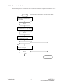
Preventative Maintenance.................................................................................................... 6 - 4
Preventative Maintenance (Table 6.2.1) .............................................................................. 6 - 4
Preventative Maintenance Diagram (Figure 6.2.1) ................................................. 6 - 5
Printer Counter Display/Clear (User) .................................................................................. 6 - 6
Printer Counter Display/Clear (Service).............................................................................. 6 - 7
Self-Diagnosis Test .............................................................................................................. 6 - 9
Self-Diagnosis Test Sample (Figure 6.5.1.) ........................................................... 6 - 10
Explanation of Self-Diagnosis Test Items ............................................................. 6 - 11
Sensor Calibration Test ...................................................................................................... 6 - 12
LED Test ............................................................................................................................ 6 - 14
Tone Send Test ................................................................................................................... 6 - 15
High-speed Modem Send Test ........................................................................................... 6 - 16
High-speed Modem Send and Receive Test Diagram (Figure 6.9.1) .................... 6 - 17
High-speed Modem Receive Test ...................................................................................... 6 - 18
MF Send Test ..................................................................................................................... 6 - 19
Tone (TEL/FAX) ............................................................................................................... 6 - 20
Protocol Data Dump Printing ............................................................................................ 6 - 21
Sample Protocol Data Dump (Figure 6.13.1) .................................................................... 6 - 22
Data Analysis (Figure 6.13.2) ............................................................................................ 6 - 23
Facsimile Control Field Conversion Table ........................................................................ 6 - 24
System Reset ..................................................................................................................... 6 - 25
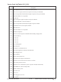
Service Code ...................................................................................................................... 6 - 27
Service Code List [Table 6.15.1] (1/2) ............................................................................. 6 - 28
Service Code List [Table 6.15.1] (2/2) ............................................................................. 6 - 29
Section 7: Troubleshooting...................................................................... 7 - 1
7.1
Overview ............................................................................................................................. 7 - 1
Service Caution ....................................................................................................... 7 - 2
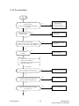
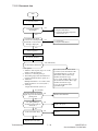
7.1.1 Overall Troubleshooting Flow Chart ....................................................................... 7 - 3
7.1.2 No LCD Operation .................................................................................................. 7 - 4
7.1.3 ALARM LED On .................................................................................................... 7 - 5
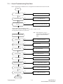
7.1.4 Printing Test Failure ................................................................................................ 7 - 6
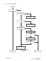
7.1.5 No Local Copy ........................................................................................................ 7 - 7
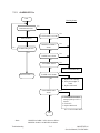
7.1.6 Auto Dial Failure ..................................................................................................... 7 - 9
7.1.7 Transmission Problem ........................................................................................... 7 - 10
7.1.8 Auto Reception Failure .......................................................................................... 7 - 13
7.1.9 Reception Problem ................................................................................................ 7 - 14
7.1.10 Sensor Calibration Test .......................................................................................... 7 - 16
7.1.11 LED Test ................................................................................................................ 7 - 17
Table of Contents
TOC - 4
OKIOFFICE 44
Service Manual, P/N 59276801
7.1.12
7.1.13
7.1.14
7.1.15
7.1.16
7.1.18
7.1.19
7.1.20
7.1.21
7.1.22
Tone Send Test ....................................................................................................... 7 - 19
High-speed Modem Test ........................................................................................ 7 - 20
MF Send Test ......................................................................................................... 7 - 22
Tone (TEL/FAX) Send Test ................................................................................... 7 - 23
No Acoustic Line Monitor ..................................................................................... 7 - 24
No Document Feeding ........................................................................................... 7 - 25
Multiple Document Feeding .................................................................................. 7 - 27
Document Skew ..................................................................................................... 7 - 28
Document Jam ....................................................................................................... 7 - 30
Printer Unit ............................................................................................................ 7 - 31
7.1.22.1 Precautions ............................................................................................. 7 - 31
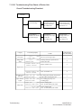
7.1.22.2 Troubleshooting Flow Charts of Printer Unit ......................................... 7 - 32
Overall Troubleshooting Flowchart ........................................................ 7 - 32
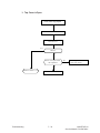
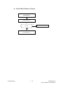
1: Top Cover is Open ............................................................................. 7 - 33
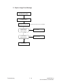
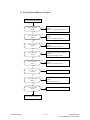
2: Replace Image Drum Message .......................................................... 7 - 34
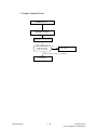
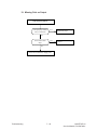
3: Engine Controller Error ..................................................................... 7 - 35
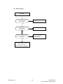
4: Fuser Unit Thermal Error .................................................................. 7 - 36
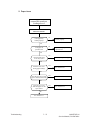
5: Paper Jams ......................................................................................... 7 - 37
6: No Paper Tray or No Paper ............................................................... 7 - 38
Action Items (Printer Unit-LCD Message) Table 7.1.22.2 ..................... 7 - 39
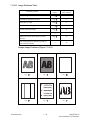
Sample Image Problems (Figure 7.1.22.1) ............................................. 7 - 40
7.1.22.3 Image Problems Table ........................................................................... 7 - 40
7: Light or Blurred Output ..................................................................... 7 - 41
8: Smeared Background on Output ....................................................... 7 - 42
9: Blank Output ..................................................................................... 7 - 43
10: Vertical Black Stripes on Output ..................................................... 7 - 44
11: Evenly Spaced Marks on Output ..................................................... 7 - 45
12: Missing Print on Output .................................................................. 7 - 46
13: Vertical White Stripes on Output ..................................................... 7 - 47
14: Poor Fusing ...................................................................................... 7 - 48
Section 8: Dipswitch Settings ................................................................. 8 - 1
8.1
General Information ............................................................................................................ 8 - 1
Table of Contents
TOC - 5
OKIOFFICE 44
Service Manual, P/N 59276801
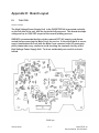
Appendix A: Board Descriptions ........................................................... A - 1
PREFACE ....................................................................................................................................... A - 1
Service Caution .................................................................................................................. A - 1
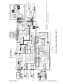
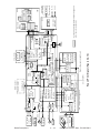
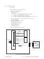
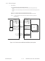
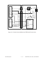
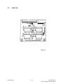
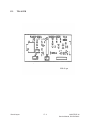
A1.1 Unit Configuration and Block Diagram ............................................................................. A - 3
OKI OFFICE44 Block Diagram Figure (A1.2.1) ............................................................... A - 4
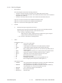
Block Diagram Abbreviations ............................................................................................ A - 5
A1.2 Function of Each Unit ........................................................................................................ A - 6
Main Control (R44) Board ................................................................................................ A - 6
Operation Panel Unit: O4W Board .................................................................................... A - 6
NCU Board (UNC5) ........................................................................................................... A - 7
Power Supply Unit ............................................................................................................. A - 7
Memory Board (Option) ..................................................................................................... A - 7
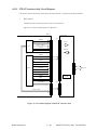
CTR Board (PC Interface) .................................................................................................. A - 7
HOOK Board (Option) ....................................................................................................... A - 7
TELU Board (Option) ........................................................................................................ A - 7
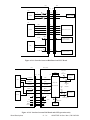
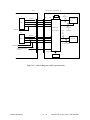
A2.1 Signal Flow Explanation .................................................................................................... A - 8
Copy Mode ......................................................................................................................... A - 8
Copy Picture Signal (Figure A2.1.1) .................................................................................. A - 9
G3 Send Mode .................................................................................................................. A - 10
G3 Send Picture Signal (Figure A2.1.2) ........................................................................... A - 11
G3 Receive Mode ............................................................................................................. A - 12
G3 Receive Picture Signal (Figure A2.1.3) ...................................................................... A - 13
300 bps Send Mode .......................................................................................................... A - 14
300 bps Send Signal (Figure A2.1.4 ) ............................................................................... A - 15
300 bps Receive Mode ..................................................................................................... A - 16
300 bps Receive Signal (Figure A2.1.5) ........................................................................... A - 17
Report Printing ................................................................................................................. A - 18
Report Print Signal (Figure A2.1.6) ................................................................................. A - 19
Memory Transmission ...................................................................................................... A - 20
Memory Reception .......................................................................................................... A - 20
A3.3 OPE (04W) Circuit Diagram ............................................................................................ A - 42
A3.5 Power Supply Unit for OKIOFFICE 44 ........................................................................... A - 44
A3.5.1 048 POW (120V/230V) Circuit Diagram ............................................................. A - 44
Block Diagram of 048 POW (Figure A3.5.1) ................................................................... A - 46
Service Caution .................................................................................................... A - 47
A3.5.2 OLHV/TLHV Circuit Diagram (2/2) ................................................................... A - 47
A3.7 UNC5 (NCU) Circuit Diagram......................................................................................... A - 51
Block Diagram of UNC (Figure A3.7.1) .......................................................................... A - 53
A3.8 TELU Circuit Diagram (Option) ...................................................................................... A - 54
Block Diagram of TEL-U (Option) Fig. A3.8.1 ............................................................... A - 55
A3.10 MEMO (Memory) Circuit Diagram (Option) .................................................................. A - 56
Related Signals of Memory Board (Option) (Figure A3.10.1) ......................................... A - 57
Table of Contents
TOC - 6
OKIOFFICE 44
Service Manual, P/N 59276801
Appendix B: Print Operation Description ............................................. B - 1
B1.1
B1.2
B1.3
B1.4
B1.5
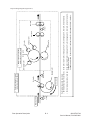
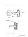
Electrophotographic Processor ........................................................................................... B - 1
Layout Drawing of Electrophotographic Processor (Figure B1.1)..................................... B - 1
Paper Feeding Diagram (Figure B1.2) ............................................................................... B - 3
Electrophotographic Process .............................................................................................. B - 4
Electrophotographic Process Diagram (Figure B1.3)......................................................... B - 5
B1.2.1 Operations Process Explanations............................................................................ B - 6
Hopping ................................................................................................................. B - 6
Printing and Warm-up ............................................................................................. B - 7
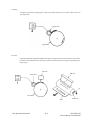
Exposure ................................................................................................................. B - 8
Charging ................................................................................................................. B - 8
Development ........................................................................................................... B - 9
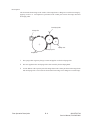
Transfer ............................................................................................................... B - 10
Fusing ............................................................................................................... B - 11
Cleaning ............................................................................................................... B - 11
Paper Feed Check List ...................................................................................................... B - 12
Paper Jam Detection ......................................................................................................... B - 12
Timing Chart for Paper Feed (Tray Feed) ........................................................................ B - 13
Toner Low Detection ........................................................................................................ B - 14
Cover Open ....................................................................................................................... B - 16
Appendix C: Circuit Diagrams................................................................ C - 1
C.1
General Information ........................................................................................................... C - 1
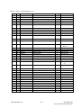
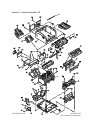
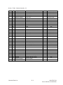
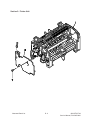
Appendix D: Illustrated Parts List .......................................................... D - 1
Section 1: Cabinet Assembly 1/2 .................................................................................................. D - 2
Section 1: Cabinet Assembly 2/2 .................................................................................................. D - 4
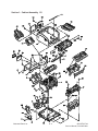
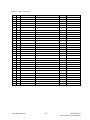
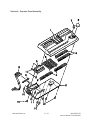
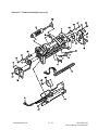
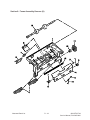
Section 2: Printer Unit ................................................................................................................... D - 6
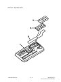
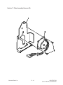
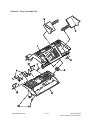
Section 3: Operator Panel .............................................................................................................. D - 8
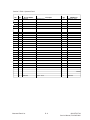
Section 4: Operator Panel Assembly ........................................................................................... D - 10
Section 5: Frame Assembly Scanner (L) ..................................................................................... D - 12
Section 6: Plate Assembly-Scanner (B) ....................................................................................... D - 14
Section 7: Plate Assembly-Scanner (R) ....................................................................................... D - 16
Section 8: Frame Assembly-Scanner (U) .................................................................................... D - 18
Section 9: Cover Assembly-Top .................................................................................................. D - 20
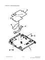
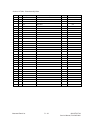
Section 10: Plate Assembly-Base ................................................................................................ D - 22
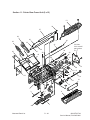
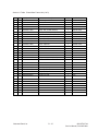
Section 11: Printer Base Frame Unit (1 of 2) .............................................................................. D - 24
Section 11: Printer Base Frame Unit (2 of 2) .............................................................................. D - 26
Section 12: Cables ....................................................................................................................... D - 28
Section 13: Miscellaneous Items ................................................................................................. D - 30
Whole Unit ....................................................................................................................... D - 30
Consumables ..................................................................................................................... D - 30
Options ............................................................................................................................. D - 30
Packaging ......................................................................................................................... D - 30
User’s Manuals ................................................................................................................. D - 31
Service (Technical) Manuals ............................................................................................ D - 31
Table of Contents
TOC - 7
OKIOFFICE 44
Service Manual, P/N 59276801
Appendix E: Board Layout ......................................................................E - 1
E.1
E.2
E.3
E.4
TLHV PCB ......................................................................................................................... E - 1
Service Caution .................................................................................................................. E - 1
MEM PCB .......................................................................................................................... E - 2
TEL-U PCB ........................................................................................................................ E - 3
Hook PCB ........................................................................................................................... E - 4
Appendix F: Second Paper Feeder ......................................................... F - 1
F.1
General Information ............................................................................................................ F - 1
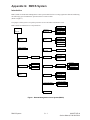
Appendix G: RMCS System.................................................................... G - 1
Introduction .................................................................................................................................... G - 1
1.
Notes to Users ..................................................................................................................... G - 2
1.1
Identifying the Packaged Contents ......................................................................... G - 2
1.2
Required Devices .................................................................................................... G - 2
1.3
Connectable Peripheral Equipment ........................................................................ G - 2
2.
Setup ................................................................................................................................... G - 3
2.1
Mounting ................................................................................................................ G - 3
2.1.1
Mounting Procedures ............................................................................... G - 3
2.2
Installation .............................................................................................................. G - 4
2.2.1
Registering the RMCS Basic System ...................................................... G - 5
2.2.2
Registering the Facsimile Model No. ...................................................... G - 8
2.2.3
Deleting the Facsimile Model No. ........................................................... G - 9
2.2.4
Updating the Password .......................................................................... G - 10
2.2.5
Updating the Dip Switches .................................................................... G - 11
2.2.6
Deleting the RMCS Basic System ......................................................... G - 12
3.
RMCS Basic Operation .................................................................................................... G - 13
3.1
Activating and Terminating the system ................................................................ G - 13
3.1.1
To Activate ............................................................................................. G - 13
3.1.2
Entering the ID and Password ............................................................... G - 13
3.2
TEL Directory ....................................................................................................... G - 14
3.2.1
To Terminate .......................................................................................... G - 14
3.2.2
Selecting Destination Drive ................................................................... G - 14
3.3
Main Menu ........................................................................................................... G - 15
3.4
Environment Setting ............................................................................................. G - 15
4.
Message Modifying Tool .................................................................................................. G - 16
4.1
Activating the Program ......................................................................................... G - 16
4.2
Modifying Message .............................................................................................. G - 16
4.2.1
File Selection ......................................................................................... G - 17
4.3
Saving Message .................................................................................................... G - 17
4.3.1
Confirmation .......................................................................................... G - 18
4.4
Loading Message .................................................................................................. G - 18
4.4.1
Confirmation .......................................................................................... G - 19
4.5
Other Message File ............................................................................................... G - 19
Table of Contents
TOC - 8
OKIOFFICE 44
Service Manual, P/N 59276801
Appendix H: Product Service Bulletins ................................................. H - 1
H.1
General Information ........................................................................................................... H - 1
OKIDATA's Web Site ......................................................................................................... H - 1
Faxable Facts ...................................................................................................................... H - 1
OKILINK II ........................................................................................................................ H - 1
Service Caution .............................................................................................................................. H - 3
Appendix I: Recommended Spare Parts List (RSPL) ............................. I - 1
I.1
General Information .............................................................................................................I - 1
OKIDATA's Web Site ...........................................................................................................I - 1
Faxable Facts ........................................................................................................................I - 1
OKILINK II ..........................................................................................................................I - 1
Table of Contents
TOC - 9
OKIOFFICE 44
Service Manual, P/N 59276801
This page was intentionally left blank.
Table of Contents
TOC - 10
OKIOFFICE 44
Service Manual, P/N 59276801
Section 1: General Information
1.1
General Performance
(1) Type of appearance
• Desktop type
(2) Applicable lines
• Public switched telephone network (PSTN)
• Private branch exchange (PBX)
(3) Compatibility
• ITU-T Group 3 facsimile transceiver
(4) Document width
• Max. 216 mm (8.5 inches [North American Letter])
• Min. 148 mm (5.83 inches [ISO A5 size])
(5) Effective reading width
• Max. 215 mm (8.46 inches)
(6) Scanning length
• 128 mm to 356 mm (5.06 inches to 14 inches)
(Length setting: Infinite is also available.)
(7) Automatic document feeder (ADF)
• 20 sheets for OKIOFFICE44 North American Letter/A4-size: 20-1b bond
• 15 sheets (North American Letter/A4-size: 13 to 28-1b bond)
(8) Recording paper or sheet
• First tray:
OKIOFFICE 44
• Manual loading feeder:
OKIOFFICE 44
North American Letter/Legal/A4-size plain paper cut
100 sheets capacity (20-1b bond*)
Transparency for overhead projector, applicable.
Sheet size: Letter/Legal/A4-size
* Recommended paper
(9) Printable width
For OKIOFFICE44
• North American:
• North American Legal:
• ISO A4:
(10) Printable length
• NA Letter:
• NA Legal:
• ISO A4:
General Information
203.2 mm (8 inches) / 203.2 mm (8 inches) for assured quality
203.2 mm (8 inches) / 203.2 mm (8 inches) for assured quality
203.2 mm (8 inches) / 197.3 mm (7.77 inches) for assured quality
273.4 mm (10.76 inches) / 266.7 mm (10.49 inches) for assured quality
349.6 mm (13.76 inches) / 342.9 mm (13.49 inches) for assured quality
291 mm (11.46 inches) / 284.3 mm (11.19 inches) for assured quality
1-1
OKIOFFICE 44
Service Manual, P/N 59276801
(11) Copy stacker
• Maximum 30 sheets (20 lb. bond *)
*: Recommended paper
(12) Scanning resolution
a) Horizontal
• 8 pels/mm
b) Vertical
Transmission mode:
COPY mode:
STD
FINE
EX. FINE
FINE
EX. FINE)
3.85 line/mm
7.7 line/mm
15.4 line/mm
7.7 line/mm
15.4 line/mm
(13) Scanning method
• 1728 bits contact image sensor
(14) Recording resolution
a) Horizontal:
300 dots/inch
b) Vertical:
Variable:
Automatically adjusted to the paper length.
STD mode (3.85 to 5.06 line/mm)
FINE mode (7.7 to 10.13 line/mm)
Fixed:
STD mode: 3.85 line/mm
FINE mode: 7.7 line/mm
EX-FINE mode : 15.4 line/mm
: 300 dot/inch
(15) Recording method
• 211.3 mm (2496 bit) or 216.7 mm (2560 bit)
(16) Minimum scan line time for reception
• When receiving from OKIFAX or ECM:
• When receiving from non- OKIFAX and non ECM:
0 ms
10 ms at 3.85 line/mm
5 ms at 7.7 line/mm
(17) Print speed
• Max. 4 sheets per minute
(18) Pre-heating time
• Approx. 30 sec. (Standby to print)
General Information
1-2
OKIOFFICE 44
Service Manual, P/N 59276801
(19) Coding scheme
• Modified Huffman (MH)
• Modified READ (MR)
• Modified Modified READ (MMR)
(20) Modem
(Rev. 2)
• ITU-T Rec. V.29:
9600/7200 bps
• ITU-T Rec. V.27 ter:
4800/2400 bps
• ITU-T Rec. V.21 channel 2:
300 bps
• ITU-T Rec. V.17:
14400/12000 bps
• ITU-T Rec. V.33:
14400/12000 bps
(21) Transmission speed
• 6 sec. per sheet of ITU-T No. 1 sample document
Note:
This is Phase C time at 3.85 line/mm and 28800 bps for 3 sec. and 14400 bps for 6 sec. in
MMR code transmission.
(22) Protocol
• ITU-T Rec. T.30
• OKI special protocols:
High-speed protocol
(23) Error correction mode (ECM)
(24) Communication mode
• Half duplex
(25) Memory capacity
• Basic model:
• Optional memory:
256k byte
1M byte memory board can be added.
(26) Liquid crystal display (LCD)
• Two rows of 20 characters for operation guidance, check and various kinds of information
(27) Power source
• Nominal input voltage 120 VAC
(28) MFP (Multi- Function Peripheral) function
• The optional board (CTR board) provides the MFP functions
PC Printer Function
PC Scanner Function
PC FaxModem Function
Location Programing Function
General Information
1-3
OKIOFFICE 44
Service Manual, P/N 59276801
1.2
General User's Function
(1) Transmit mode
• Automatic transmit mode
• Manual transmit mode
(2) Receive mode
• Automatic receive mode
• Manual receive mode
• TEL/FAX automatic switchover mode
• TAD mode
• PC Mode
(3) Dual Access
Not available for the OKIOFFICE 44
(4) Voice request
(5) Automatic redial
(6) Last number redial (Manual redial)
(7) Local copy including multiple copies
• Maximum 50 copies of document
(8) Sender identification (Sender ID)
(9) Personal identification (Personal ID)
(10) Polling transmission
(11) Polling reception
(12) Acoustic line monitor
(13) Telephone handset (option)
(14) Automatic alternate selecting call (FAX No. + FAX No. can be registered in one-touch keys).
(15) Delayed transmission (Maximum length of delay 3 days)
• Delayed broadcast
• Delayed transmission
1 specified time
(16) Relay broadcast initiate
(17) Confidential message transmission (Hopper 1 station)
(18) Confidential message reception
Not Available for the OKIOFFICE 44
(19) PHOTO mode
• 16 scale gradations (Dither Method)
General Information
1-4
OKIOFFICE 44
Service Manual, P/N 59276801
(20) G3 sequential broadcast (Memory)
• Broadcast mode
56 stations at maximum
• Delayed broadcast mode
(21) No paper/no toner reception
(22) Memory-only reception
Not available for the OKIOFFICE 44
(23) Distinguishing Text from picture
(24) Page re-transmission (Only in case of memory TX mode)
Retransmits in page units
(25) Reduction printing (Reduction rate is from 100% to 75%.) (Legal to Letter)
(26) Smoothing printing (In case of 3.85R/mm → 7.7R/mm)
(27) Programmed key operation (“F” key + “OT” key)
(28) Auto dialing
• One-touch dialing
10 locations, maximum of 32 digits each location
• Two-digit automatic dialing
45 locations, maximum of 32 digits each location
• Keypad dialing
• Chain dialing
• Mixed dialing
• Group dialing
5 dialing groups, maximum of 55 locations each group
(29) Realtime dialing
(In case of optional handset is installed or Hook key)
(30) Automatic pause signal insertion
(31) Manual feeder local copy
(32) Telephone directory (Alpha search) dialing
(33) TEL/FAX automatic switching
(34) Time and date printing
(35) Closed users group (Direct mail rejection)
(36) Transmission contrast and resolution control
(37) Key touch tone
(38) Printer counter display (For drum, toner, total print)
(39) Total page counter (Scan)
(40) Quick scanning
Not available for the OKIOFFICE 44
General Information
1-5
OKIOFFICE 44
Service Manual, P/N 59276801
(41) Date and clock adjustment
(42) PC interface
• Standard
(43) Language selection
• 2 languages (LCD and Reports)
English / Spanish
English / French
(42) Fax forwarding
Not available for the OKIOFFICE 44
(44) Reports
• Activity report
• Protocol report (Service man setting)
• Message confirmation report (Single address or multiple addresses)
• Broad cast entry report (Broadcast)
• Transmission error report
• Confidential reception report
• Configuration report
• Telephone directory
• Power outage report
General Information
1-6
OKIOFFICE 44
Service Manual, P/N 59276801
1.3
General Maintenance Functions
(1) Self-diagnosis
• CPU ROM/RAM check
• FLASH (/MASK) memory check (Program, Language, Default)
• RAM check
• RAM check (MEMORY board: option)
• PC-IF board (parallel) check
• Print test
(2) Sensor calibration (Adjustment of scanning level)
(3) LED test
(4) Tone send test
(5) Multi-frequency (MF) send test
(6) High-speed modem send test
(7) High-speed modem receive test
(8) Tone (TEL/FAX) test
(9) Remote diagnosis
(10) System reset
(11) Service default report (Machine setting for service engineer)
General Information
1-7
OKIOFFICE 44
Service Manual, P/N 59276801
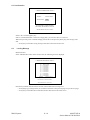
1.4
General Appearance
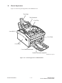
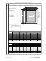
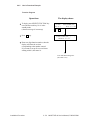
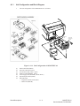
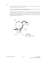
Figure 1.4.1 shows the general appearance of the OKIOFFICE 44
Tray-Paper
Tray-Document
Cover-Top
Case-OPE (T)
Cover-Front
Cover-Main
Cover Manual Document
Stacker-Document (Optional)
(FX048 CP4.1 Fig. 01)
Figure 1.4.1 General Appearance of OKIOFFICE44
General Information
1-8
OKIOFFICE 44
Service Manual, P/N 59276801
1.5
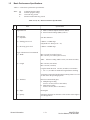
Basic Performance Specifications
Table 1.5.1 shows basic performance specifications.
Note:
TF:
FP:
OT:
F:
Technical function setting
Function program setting
One-touch key pressed
SELECT FUNCTION key pressed
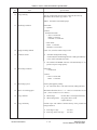
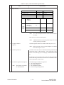
Table 1.5.1 (1/11) Basic Performance Specifications
No.
Item
1
Applicable line
2
Line interface
1) Impedance
3
Specifications
1) Public switched telephone network (PSTN)
2) Private branch exchange (PBX) (OT9+2)
600 ohms balanced
2) Sending power level
0 dBm to –15 dBm range
(Adjustable in 1 dB steps. TF + 22)
3) Receiving power level
0 dBm to –40 dBm range
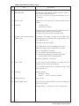
Type of document to be transmitted
1) Width
Max. 216 mm [8.5 inches] (Letter)
Min. 148 mm [5.83 inches] (ISO A5 size)
Note:
2) Length
Effective reading width is Letter (215 mm/8.46 inches).
Min. 128 mm (5.04 inches)
Max. 356 mm (14 inches)
Long document detection: 356 mm (14 inches) or 60 minutes
* TF + 11 (To enable or disable the long document scanning)
An operator can turn the long document scanning feature on or off
for each call in the operating sequence.
3) Thickness
Based on common bond paper,
a) Multiple Page Feeding
0.08 to 0.13 mm (0.003 to 0.005 inches)
b) Single Page Feeding
0.06 to 0.15 mm (.002 to .006 inches)
4) Shape
Rectangular
5) Opacity
Documents allowing less than 40% of the scanner source light to
pass through them.
General Information
1-9
OKIOFFICE 44
Service Manual, P/N 59276801
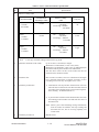
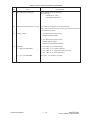
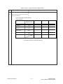
Table 1.5.1 (2/11) Basic Performance Specifications
No.
4
Item
Specifications
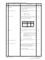
Effective reading width
Document Width
ISO A4
210 mm
8.27 inches
Letter
216 mm
8.5 inches
Legal
216 mm
8.5 inches
Note
Communication
Mode/Paper width
Effective reading
width
208 mm
8.19 inches
Local Copy: 200 mm
7.87 inches
Copy size
TX:
G3/A4
TX:
215 mm
8.46 inches
Local Copy: 200 mm
7.87 inches
G3/A4
G3/A4
TX:
215 mm
8.46 inches
Local Copy: 200 mm
7.87 inches
A4
Letter
Legal
Local copy: Printable reading width in local copy mode
5
Automatic document feeder (ADF)
Up to 297 mm (11.69 inches) in length.
Maximum of. 20 documents, Letter or A4 (20-1b)
Maximum of 15 documents: Letter or A4 (13-28lb bond paper)
Documents shall be placed facedown on ADF stacker.
The first sheet will be fed first in the feeder and will exit
facedown in the document stacker.
6
Document skew
Max. 2.6 mm (.102 inches) skew over a document of A4 length.
For a document longer than A4 length, occurrence of skew
exceeding 2.6 mm over any A4 length is 0.5% or less.
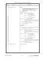
7
Document jam detection
1) Transmission will stop and line disconnection will occur
when the end of a document is not detected within 356 mm
(14 inches) after scanning begins (except for the long document scanning. Technical Function 11)
2) A jam will also be declared if the document does not reach
the scanning position within 10 seconds after the start of a
document feed.
Note: When a jam is detected during message transmission
from the feeder, the machine will stop scanning and
disconnect the line, but its receiving capability will
remain valid.
8
Document jam removal
General Information
Manual release
1 - 10
OKIOFFICE 44
Service Manual, P/N 59276801
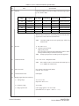
Table 1.5.1 (3/11) Basic Performance Specifications
No.
9
Item
Recording paper or sheet
Specifications
NOTE:
For best results, use Okidata recommended papers
Xerox 4200 (20 lb/base weight paper)
Paper approved for xerographic (copier/laser)
printing process
Automatic Feed
1) Type:
Plain paper cut (Bond paper)
2) Size:
A4:
210 x 297 millimeters
8.27 x 11.69 inches
Letter:
215.9 x 279.4 millimeters
8.5 x 11 inches
Legal:
215.9 x 355.6 millimeters
8.5 x 14 inches
3) Weight:
16 lbs to 24 lbs/base weight
Base weight is defined as the weight of 500 sheets
of 431.8 mm (17 inch) by 558.8 mm (22 inch).
4) Thickness: 0.08 mm to 0.12 mm
.0031 inches to .0047 inches
5) Condition: New paper
Manual Feed
Note: One single sheet only should be loaded on the manual
loading feeder for any one occasion.
1) Type:
Plain paper, transparency for overhead projector,
colored paper, printed paper
Must meet specifications for xerographic printing
process
2) Size:
A4:
210 x 297 millimeters
8.27 x 11.69 inches
Letter:
215.9 x 279.4 millimeters
8.5 x 11 inches
Legal:
215.9 x 355.6 millimeters
8.5 x 14 inches
3) Weight:
16 lbs to 24 lbs/base weight
Base weight is defined as the weight of 500 sheets
of 431.8 mm (17 inch) by 558.8 mm (22 inch).
4) Thickness: 0.08 mm to 0.12 mm
.0031 inches to .0047 inches
10
Recording paper cassette
General Information
100 sheets/tray (20 lb.)
1 - 11
OKIOFFICE 44
Service Manual, P/N 59276801
Table 1.5.1 (4/11) Basic Performance Specifications
No.
Item
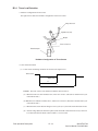
L
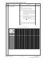
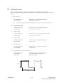
11
Effective recording area
T
PL = Page Length
PW = Page Width
EL = Effective Length
EW = Effective Width
T = Top Margin
B = Bottom Margin
L = Left Margin
R = Right Margin
PL
EL
B
Note:
1)
These tables do not
include vertical and horizontal addressing deviations
(+ or –2 mm) of recording
paper.
PW
EW
R
Printing area
Recording
paper
feed
direction
(F050-C1-001)
Printable area
NA LETTER SIZE
inch
mm
11
279.4
8.5
216
10.76
273.4
8.0
203.2
0.12
3
0.12
3
0.25
6.35
0.25
6.35
PL
PW
EL
EW
T
B
L
R
2)
,QRSTUVWXY¢£¤¥¦§¨©ª
Specifications
ISO A4 SIZE
inch
mm
11.7
297
8.27
210
11.46
291
8.0
203.2
0.12
3
0.12
3
0.13
3.4
0.13
3.4
14 inch LEGAL SIZE
inch
mm
14
355.6
8.5
216
13.76
349.6
8.0
203.2
0.12
3
0.12
3
0.25
6.35
0.25
6.35
13 inch LEGAL SIZE
mm
inch
330.2
13
ISO A4 SIZE
inch
mm
11.7
297
8.27
210
11.2
284.3
7.77
197.3
0.25
6.35
0.25
6.35
0.25
6.35
0.25
6.35
14 inch LEGAL SIZE
inch
mm
14
355.6
8.5
216
13.5
342.9
8.0
203.2
0.25
6.35
0.25
6.35
0.25
6.35
0.25
6.35
13 inch LEGAL SIZE
mm
inch
330.2
13
8.5
12.76
8.0
0.12
0.12
0.25
0.25
216
324.2
203.2
3
3
6.35
6.35
Guaranteed printing area
PL
PW
EL
EW
T
B
L
R
General Information
NA LETTER SIZE
inch
mm
11
279.4
8.5
216
10.5
266.7
8.0
203.2
0.25
6.35
0.25
6.35
0.25
6.35
0.25
6.35
1 - 12
8.5
12.5
8.0
0.25
0.25
0.25
0.25
216
317.5
203.2
6.35
6.35
6.35
6.35
OKIOFFICE 44
Service Manual, P/N 59276801
Table 1.5.1 (5/11) Basic Performance Specifications
No.
12
Item
Copy stacking
Specifications
The fax can discharge printed copies and stack them faceup.
Maximum sheets on the copy stacker: 30*
Note*: Oki Data recommended paper
13
Scanning resolution
Horizontal:
• 8 pel/mm
Vertical:
Transmission mode:
• STD 3.85 line/mm
FINE 7.7 line/mm
EX.FINE 15.4 line/mm
COPY mode:
FINE: 7.7 line/mm
EXFINE 15.4 line/mm
14
Image scanning method
Letter size (1728-bit) contact image sensor
15
Contrast control
1) Automatic background sensing
A continuous document background of 0.3 OD (optical density)
or less will be transmitted as white.
2) The LIGHT and DARK contrasts will automatically be adjusted to improve image quality.
16
Recording resolution
Horizontal:
• 300 dot/inch
Vertical:
• STD: 3.85 line/mm
FINE: 7.7 line/mm
17
Recording system
Electro-photographic printing
1) 211.3mm (2496 bit) or 216.7mm (2560 bit) LED print head
18
Skew of recording paper
Maximum allowable skew is + or - 1 mm over an advance of 100
mm. (.03937 inches over 3.937 inches)
19
Copy darkness
1) Black image:
2) White background:
20
Copy uniformity
Printed copies will exhibit a uniform density of the printed and
background area:
Greater than 1.0 OD (Optical density)
Not greater than 0.2 OD
(Optical density)
1) From edge to edge:
2) From copy to the next copy:
General Information
1 - 13
25% unit
30% unit
OKIOFFICE 44
Service Manual, P/N 59276801
Table 1.5.1 (6/11) Basic Performance Specifications
No.
Item
Specifications
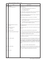
21
Recording paper running out
22
Minimum scan line time for receiving 0 ms, when receiving from an Oki Data facsimile.
5 ms at 7.7 line/mm and 10 ms at 3.85 line/mm when receiving from
a non-Oki Data facsimile.
23
Coding scheme
Detected during print operation only.
Error Message:
PAPER OUT / JAM
CONFIRM AND“STOP”
1) One-dimensional coding scheme:
Modified Huffman (MH)
2) Two-dimensional coding scheme:
Modified READ (MR)
Modified modified READ (MMR)
24
MODEM
1) High-speed MODEM
a)
b)
c)
d)
2) Low-speed MODEM
ITU-T Rec. V.21 channel 2 (300 bps)
General Information
ITU-T Rec. V.29 (9600/7200 bps)
ITU-T Rec. V.27 ter (4800/2400 bps)
ITU-T Rec. V.17 (14400/12000/9600/7200 bps)
ITU-T Rec. V.33 (14400/12000 bps)
1 - 14
OKIOFFICE 44
Service Manual, P/N 59276801
Table 1.5.1 (7/11) Basic Performance Specifications
No.
25
Item
Specifications
Automatic fallback will occur according to the following sequence
by FTT, RTN or PPR.
Fallback
Activated by Activated by
RTN (Times) PPR (Times)
Fallback
rank
Transmission
speed
Activated by
FTT (Times)
1st
14400 bps
1
1
4 (Note 1)
ITU-T V.17 (V.33)
2nd
12000 bps
1
1
4 (Note 1)
ITU-T V.17 (V.33)
3rd
9600 bps
1
1
4 (Note 1)
ITU-T V.17 (V.29)
4th
7200 bps
1
1
4 (Note 1)
ITU-T V.17 (V.29)
5th
4800 bps
2
1
4 (Note 1)
ITU-T V.27 ter.
6th
2400 bps
2
1
4 (Note 1)
ITU-T V.27 ter.
Protocol
When the last trial fails, the transmitting station sends out a DCN
signal to the remote station for disconnection.
Note:
Continuous PPRs for the same partial page within each
fallback rank.
26
Protocol
1) ITU-T Rec. T.30
2) Oki Data special protocol
High-speed protocol
The T.30 protocol signal from the transmitting station is sent at
message transmission speed instead of 300 bps.
Note: In high-speed protocol, 28.8 K-bps are not supported.
27
Transmission time
6 sec. /ITU-T No. 1 sample document
Note:
This is Phase C time at 3.85 line/mm and 14400 bps for 6
sec. in MMR code transmission.
28
Error correction
ITU-T Error correction mode (ECM)
Oki Data ITU-T ECM
29
Communication mode
Half-duplex
30
Ringing signal detection sensitivity
1) Voltage range
25 to 150 V r.m.s.
Inoperative below 10 V
2) Frequency range
20 to 68 Hz
3) Ring response time
One-ringing signal or 5 to 30 seconds.
(Selectable in 5 sec. steps. F + OT9 + ← + 11)
General Information
1 - 15
OKIOFFICE 44
Service Manual, P/N 59276801
Table 1.5.1 (8/11) Basic Performance Specifications
No.
31
Item
Specifications
Image memory
OKIOFFICE44
Basic model
Optional memory
256K-byte
1M-byte
Memory
condition
With
option
board
Standard
(without option)
20
1M-byte
100
2M-byte
N/A
Note:
ITU-T No.1 sample document is used to count the number
of sheets.
Back-up time on electrical interruption:
Note:
32
Telephone handset
(option)
OKIOFFICE44 does not back up the message received in
memory for the power failure.
General telephone function is available while the power is on.
Note: In the fax special versions, general telephone is available
even when the power is off.
34
Overheat protection
The heater of the fuser unit is controlled within the predetermined
temperature range by the thermistor. If the temperature of the
heater exceeds the range, the LCD displays “PRINTER ALARM
4”.
Furthermore, the built-in thermostat in the fuser unit prevents the
heater from being overheated even in the event of the failures in the
above temperature control circuit.
35
PC interface applications (Option)
Note:
This function is standard
for OKIOFFICE44.
General Information
The following four modes are supported:
1) PC local printer function
2) PC scanner function
3) PC FaxModem function
4) Location Programing function
1 - 16
OKIOFFICE 44
Service Manual, P/N 59276801
Table 1.5.1 (9/11) Basic Performance Specifications
No.
36
Item
Specifications
Power supply unit and power consumption of the machine
Power consumption of the machine
(Typical power)
OKIOFFICE44
Transmit
19W
Receive
115W
Local copy
Standby
150W
10W
** Power save mode is automatic for the OKIOFFICE 44.
It cannot be enabled or disabled by the user.
General Information
1 - 17
OKIOFFICE 44
Service Manual, P/N 59276801
Table 1.5.1 (10/11) Basic Performance Specifications
No.
Item
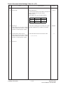
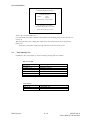
37
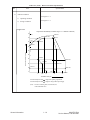
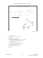
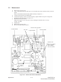
Ambient condition
Specifications
See Figure 1.5.1
1) Operating condition
See Figure 1.5.1
2) Storage condition
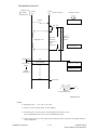
Figure 1.5.1
Temperature and Humidity Conditions (Figure 1.5.1 Ambient Conditions)
90
85%
28°C85%
18°C80%
80
27°C80%
73%
10°C73%
70
0°C64%
60
32°C54%
Relative humidity [%RH]
50
40
10°C30%
30
43°C29%
15°C20%
20
10
32°C20%
0°C10%
43°C10%
28°C
18°C
27°C
0
10
15°C
20
30
40
43°C
TEMPERATURE [°C]
Area enclosed by lines with
Area enclosed by lines with
(Note)
General Information
: Range where printing is guaranteed.
: Range for storage without power supply.
The curve connecting 28°C, 85% and 0°C, 64%
is the condensation curve.
1 - 18
OKIOFFICE 44
Service Manual, P/N 59276801
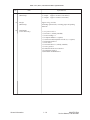
Table 1.5.1 (11/11) Basic Performance Specifications
No.
Item
Specifications
38
Dimension
(Main body)
1) Width:
2) Depth:
3) Height:
39
Weight
(Main body)
Approx. 8 kg (17.6 lbs)
Excluding optional units, recording paper and packing
materials.
40
Attachments
(to the main body)
General Information
Approx. 312 mm (12.28 inches)
Approx. 383 mm (15.08 inches)
Approx. 190 mm (7.48 inches)
1) AC power cord x 1
2) I/D unit x 1 (Already installed)
3) Toner cartridge x 1
4) Telephone handset x 1 (option)
5) Curled cord and Telephone cord for (4) x 1 (option)
6) Document stacker x 1
7) Line cord x 1
8) One touch sheet x 1 (Already installed)
9) User’s guide x 1
10) JetSuite Software User Guide x 1
11) Quick Start Guide x 1
12) WordScan OCR Manual x 1
1 - 19
OKIOFFICE 44
Service Manual, P/N 59276801
1.6
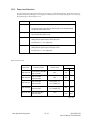
Reports and Lists
Table 1.6.1 shows Reports and Lists Specifications.
Note:
F +OT: Press FUNCTION and One-touch key
FP:
Function program setting
TF:
Technical function setting
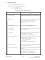
Table 1.6.1 (1/2) Reports and Lists Specifications
No.
Item
Specifications
1
Call-back message
The transmitter sends a call-back message to the receiver only
when the receiver does not respond to voice request of the transmitter.
2
Sender ID
The fax can transmit a programmed alphanumeric message, such as
company’s name, consisting of up to 32 characters.
This is an FCC Requirement in the United States
* (Outside only)
3
Transmitting subscriber identification (TSI) printing
Received TSI can be printed at the top of the received page.
* TF + 05 (To enable or disable this function)
4
Cancel report
(Power outage report)
The fax can automatically print out a power-outage report when the
power off condition occurs.
5
Activity report
The fax can print out an activity report manually, or automatically,
when 30 communications are recorded.
* REPORT PRINTOUT+1 (Manual printout)
6
Message confirmation report
The fax can print out a message confirmation report manually or
automatically in the following cases.
(1) When COPY key is pressed after a single location
call, this report can be printed.
(Manual printout)
* FP + 01 (To enable or disable automatic printing)
7
Broadcast entry report
The fax can print out a broadcast entry report if specified during
operating sequence of a broadcast.
8
Broadcast confirmation report
The fax can print out a broadcast confirmation report manually or
automatically.
* COPY key (Manual printout): Pressed after a broadcast.
* REPORT PRINTOUT + 2 (Manual printout)
* FP +02 (To enable or disable automatic printing)
General Information
1 - 20
OKIOFFICE 44
Service Manual, P/N 59276801
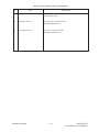
Table 1.6.1 (2/2) Reports and Lists Specifications
No.
Item
Specifications
9
Confidential reception report
The fax can print out this report automatically on completion of a
confidential reception.
10
Telephone directory
This directory is printed manually.
(REPORT PRINTING +3)
11
Configuration report
This report is printed manually.
(REPORT PRINTING +4)
General Information
1 - 21
OKIOFFICE 44
Service Manual, P/N 59276801
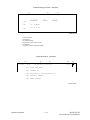
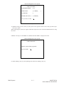
Call-back Message Format: (Example)
(1)
(2)
07/01/96
(3)
OKI SHIBAURA → OKI HONJO
09:24
(4)
PLEASE
CALL
(5)
OKI
(6)
=103 5476 1234
NO.002
BACK
SHIBAURA
(F050-C1-002)
(1)
(2)
(3)
(4)
(5)
(6)
Date and time
Sender ID
CSI/Personal ID
Letters "PLEASE CALL BACK"
Sender ID
Sender's call back telephone number
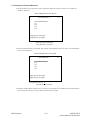
Sender ID Format: (Example)
(1)
07/01/96
~
(2)
15:06
(3)
OKI ABC 1234 → 3454 2000
(1)
Date and Time
(2)
Sender ID
(3)
Receiver's CSI/Personal ID
(4)
Session number
(5)
Page number
(4)
(5)
NO.021
01
~
(F050-C1-003)
General Information
1 - 22
OKIOFFICE 44
Service Manual, P/N 59276801
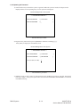
TSI Printing and Local Date and Time Printing Format: (Example)
07/01/96
15:48
3454 1999
TSI printing
~
Local date and time printing
~
(F050-C1-004)
Note: TSI printing (TF+05)
Local date and time printing (TF+04)
General Information
1 - 23
OKIOFFICE 44
Service Manual, P/N 59276801
This page was intentionally left blank.
General Information
1 - 24
OKIOFFICE 44
Service Manual, P/N 59276801
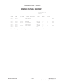
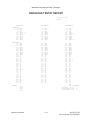
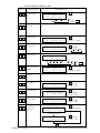
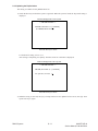
Cancel Report Format: (Example)
POWER OUTAGE REPORT
05/19/96
ID=OKI
S,R-TIME
DISTANT STATION ID
MODE
17:05
DATE
TIME
PAGES
RESULT
05/17
10:10
0485-88-3385
05/17
10:30
ODS TAKASAKI
05/17
12:05
01'20"
OKI FAX
BOX=01
03
OK
0000
05/17
13:00
00'20"
03-5476-4300
CALLED
01
OK
0000
05/17
05/18
15:40
10:50
01'20"
034567092222
0495-22-5400
FWD-T
CALLED
05
03
OK
0000
05/18
15:00
B.C.
01
9080
03
0000
Note: Memory reception only is printed on the mode in the report as called.
General Information
1 - 25
OKIOFFICE 44
Service Manual, P/N 59276801
(1)
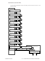
Message Confirmation Report Format: (Example)
ACTIVITY REPORT
(2) 05/19/96 17:05
(3) ID=OKI
(4) TOTAL
TIME
CALLING=08:22'
CALLED=17:30'
DISTANT STATION ID
(8)
OKI FAX
MODE
(9)
CALLING
PAGES
(10)
02
CALLING
CALLING
00
00
DATE
(5)
05/17
TIME
(6)
10:00
S,R-TIME
(7)
01'20"
05/17
05/17
10:10
10:30
01'00"
00'20"
0485 88 3385
ODS TAKASAKI
05/17
12:05
01'20"
OKI FAX
CALLING
03
OK
0000
05/17
13:00
00'20"
03 5476 4300
CALLING
01
OK
0000
BOX=01
03
OK
0000 *1
01
OK
0000 *2
05
00
NO
STOP
908E
9080
05/17
15:40
03'25"
ODS TAKASAKI
05/17
19:00
00'00"
OKI FAX
05/18
05/18
10:10
10:22
02'00"
00'12"
OKI SHIBAURA
0495 22 5400
CALLED
CALLING
RESULT
(11)
OK
(12)
0000
STOP
NO
9080
90C1
05/18
10:50
01'20"
0495 22 5400
CALLED
03
NO
9090
05/18
12:05
00'20"
OKI FAX
CALLING
01
STOP
9080
05/18
15:00
01'30"
CALLED
03
OK
0000 *3
05/18
15:30
00'20"
CALLING
01
OK
0000
05/18
05/18
17:05
19:04
05'20"
00'20"
03 5476 4300
B.C.
CALLING
00
COMP.
STOP
60A0 *4
9080
05/19
09:00
01'11"
CALLING
02
OK
0000
05/19
10:20
00'20"
03 5476 4300
CALLING
02
STOP
9080
05/19
10:35
02'23"
BOX=01
02
OK
0000 *1
05/19
10:50
00'20"
ODS TAKASAKI
CALLED
01
OK
0000
05/19
05/19
11:03
13:00
00'00"
00'24"
OKI FAX
03 5476 4300
CALLING
00
01
STOP
NO
9080
0000 *5
05/19
16:00
03'25"
ODS TAKASAKI
FWD-R
03
OK
0000 *6
05/19
16:04
03'30"
OKIFAX
FWD-T
03
OK
0000 *7
*1 :
*2 :
*3 :
*4 :
*5 :
*6 :
*7 :
General Information
1 - 26
Confidential reception
Manual TX
Memory reception
Broadcast TX
Manual reception
Reception for forwarding
Forwarding
OKIOFFICE 44
Service Manual, P/N 59276801
(1)
(2)
(3)
(4)
(5)
(6)
(7)
(8)
Title of the report
Date and time when the report was printed
Sender ID
Total CALLING and CALLED time
Date of transmission or reception
Time when the communication started
Time span of the fax communication.
Identification of the remote station
Personal ID/Location ID/TSI/CSI/Dial number or space
(9) Communication mode:
(Rev.2)
CALLING
(Transmission)
CALLED
(Reception NG or MEMORY RX)
B. C.
(Broadcast)
BOX=XX
(Confidential reception)
FWD-R (Fax Forwarding RX)
FWD-T (Fax Forwarding TX)
(10) Number of transmitted pages or received pages
(11) Result code
OK (Note1)/NO/STOP (Note 2)/BUSY/PAPER (Out of recording paper)/S_JAM (Document
jam)/R_JAM (Recording paper jam)/COVER/COMP (Completion of a broadcast)/PUNIT
(Printer Alarm)/CANCL (Confidential reception T.O.)
Note 1:
The following cases are included:
• Unmatched handshaking to the received NSF.
• Unmatched password to the received NSC in the polling transmission mode.
Note 2:
The following cases are included:
• The STOP key is pressed.
• The memory cancellation operation removes the message from the active memory files.
(12) Service code
General Information
1 - 27
OKIOFFICE 44
Service Manual, P/N 59276801
Message Confirmation Report Format (1/2): (Example)
(1)
MESSAGE CONFIRMATION
(2)
(3)
(4)
DATE
(5)
S.R-TIME
07/01
00'20"
(6)
DISTANT STATION ID
OKI FAX
(7)
MODE
CALLING
07/01/96 08:05
ID=OKI
(8)
(9)
PAGES RESULT
02
OK
(10)
0000
(F050-C1-008 1/2)
General Information
1 - 28
OKIOFFICE 44
Service Manual, P/N 59276801
Message Confirmation Report Format (2/2): (Example)
(1)
MESSAGE CONFIRMATION
(2)
(3)
(4)
DATE
(5)
S.R-TIME
(6)
DISTANT STATION ID
07/01
00'20"
OKI FAX
07/01/96
17:00
OKI
OKIFAX
(7)
MODE
07/01/96 17:05
ID=OKI
(8)
(9)
PAGES RESULT
B.C.
01
No.022
001
COMP
(10)
60A0
150 km
(11)
(F050-C1-008 2/2)
(1)
(2)
(3)
(4)
(5)
(6)
(7)
(8)
(9)
(10)
(11)
Title of the report
Date and time when the report was printed
Sender ID
Date of transmission or reception
Length of time for which the fax was connected to the line
Identification of the remote station
Personal ID/Location ID/TSI/CSI/Dial number
Communication mode
Reference to ACTIVITY REPORT
Number of transmitted pages or received pages
Result of the communication
Reference to ACTIVITY REPORT
Service code
Message
General Information
1 - 29
OKIOFFICE 44
Service Manual, P/N 59276801
Broadcast Entry Report Format: (Example)
BROADCAST ENTRY REPORT
07/01/96
ID=OKI
LOCATION ID
LOCATION ID
17:05
LOCATION ID
ONE TOUCH
1 =
4 =
7 =
10 =
13 =
16 =
19 =
22 =
25 =
28 =
OT1
OT4
OT7
OT10 *1
OT13
OT16
OT19
OT22
OT25
OT28
2
5
8
11
14
17
20
23
26
29
=
=
=
=
=
=
=
=
=
=
OT2
OT5
OT8
OT11
OT14
OT17
OT20
OT23
OT26
OT29
3
6
9
12
15
18
21
24
27
30
=
=
=
=
=
=
=
=
=
=
AUTO DIAL
01 =
04 =
07 =
10 =
13 =
16 =
19 =
22 =
25 =
28 =
31 =
34 =
37 =
40 =
43 =
46 =
49 =
52 =
55 =
58 =
61 =
64 =
67 =
70 =
73 =
76 =
79 =
82 =
85 =
88 =
91 =
94 =
97 =
AD1
AD4
AD7
AD10
AD13
AD16
AD19
AD22
AD25
AD28
31
34
37
40
43
46
49
52
55
58
61
64 *2
67
70
73
76
79
82
85
88
91
94
97
02
05
08
11
14
17
20
23
26
29
32
35
38
41
44
47
50
53
56
59
62
65
68
71
74
77
80
83
86
89
92
95
98
=
=
=
=
=
=
=
=
=
=
=
=
=
=
=
=
=
=
=
=
=
=
=
=
=
=
=
=
=
=
=
=
=
AD2
AD5
AD8
AD11
AD14
AD17
AD20
AD23
AD26
AD29
32
35
38
41
44
47
50
53
56
59
62
65
68
71
74
77
80
83
86
89
92
95
98
03
06
09
12
15
18
21
24
27
30
33
36
39
42
45
48
51
54
57
60
63
66
69
72
75
78
81
84
87
90
93
96
99
=
=
=
=
=
=
=
=
=
=
=
=
=
=
=
=
=
=
=
=
=
=
=
=
=
=
=
=
=
=
=
=
=
KEYPAD
1234
2345
3456
4567
General Information
1 - 30
OT3
OT6
OT9
OT12
OT15 *2
OT18
OT21
OT24
OT27
OT30 *3
AD3
AD6
AD9
AD12
AD15
AD18
AD21
AD24
AD27
AD30
33
36
39
42
45 *1
48
51
54
57
60
63
66
69
72
75
78
81
84
87
90
93
96
99
MAX.
OT AD KEYPAD
*1 FX-480 : 10 45
1
*2 FX-050VP : 15 64
5
*3 FX-175VP : 30 99
5
OKIOFFICE 44
Service Manual, P/N 59276801
Broadcast Confirmation Report Format: (Example)
BROADCAST CONFIRMATION REPORT
PAGES
= 01
TOTAL TIME
= 00:02'30"
LOCATION ID
07/01/96 17:05
ID=OKI
PAGES
RESULT
LOCATION ID
PAGES
RESULT
ONE TOUCH
1 = OT1
3 = OT3
5 = OT5
01
01
01
OK
OK
OK
2 = OT2
4 = OT4
01
01
OK
OK
AUTO DIL
01 = AD1
03 = AD3
05 = AD5
01
01
01
OK
OK
OK
02 = AD2
04 = GERMAN
01
01
OK
OK
01
01
01
OK
OK
OK
KEYPAD
1234
3456
5678
(F030-C1-010)
Confidential Reception Report Format: (Example)
CONFIDENTIAL RX REPORT
07/01/96
ID=OKI
DATE
TIME
07/01
00:20
General Information
S,R-TIME
00'00"
DISTANT STATION ID
MODE
OKI
BOX=01
FAX
1 - 31
17:05
PAGES
02
RESULT
OK
0000
OKIOFFICE 44
Service Manual, P/N 59276801
Telephone Directory for OKIOFFICE 44 (1/2): (Example)
TELEPHONE DIRECTORY P1
07/01/96 19:19
ID=OKI DATA CORP.
LOCATION ID
ONE TOUCH
1
TEL NO.
OKI SERVICE
OR
2
OKI OFFICE
OR
3
OKI LABORATORY
OR
4
ODC TAKASAKI
OR
5
ODC QA/QC LAB.
OR
123 123 123
111 222 333
456 456 456
444 555 666
789 789 789
777 888 999
000 111 222
444 555 666
1234 5678 90123
123 123 123
6
PRM. ECHO
(OFF)
(OFF)
(OFF)
(OFF)
(OFF)
(OFF)
OR
7
(OFF)
OR
8
(OFF)
OR
9
(OFF)
OR
10
(OFF)
OR
AUTO DIAL
01
02
03
04
05
06
07
08
09
10
11
12
13
14
15
16
17
18
19
20
21
22
23
24
25
26
27
28
29
30
31
32
33
34
35
36
37
38
39
40
41
42
43
44
45
ODC TAKASAKI
General Information
0273 28 1234
1 - 32
OKIOFFICE 44
Service Manual, P/N 59276801
Telephone Directory for OKIOFFICE 44 (2/2): (Example)
TELEPHONE DIRECTORY P2
07/01/96 19:20
ID=OKI DATA CORP.
GROUP NUMBER = #1 #2 #3 #4 #5
#1 ONE TOUCH
1 2
3
4
5
6
7
8
9 10
AUTO DIAL
01 02 03 04 05 06 07 08 09 10 11 12 13 14 15 16 17 18 19 20 21 22 23 24 25
26 27 28 29 30 31 32 33
#2 ONE TOUCH
AUTO DIAL
#3 ONE TOUCH
AUTO DIAL
#4 ONE TOUCH
AUTO DIAL
#5 ONE TOUCH
5
AUTO DIAL
07
General Information
1 - 33
OKIOFFICE 44
Service Manual, P/N 59276801
Configuration Report (User)
NOTE:
The function settings shown ARE NOT
the factory defaults.
Refer to Section 2 for the technical function setting defaults.
CONFIGURATION
07/01/96
ID=OKI
17:05
FUNCTION LIST
01:MCF (SINGLE-LOC.)
02:MCF (MULTI-LOC.)
ON
03:ERR.REPORT (MCF)
ON
ON
04:MESSAGE IN MCF
ON
05:SENDER ID.
ON
06:MONITOR VOLUME
LOW
07:BUZZER VOLUME
08:CLOSED NETWORK
09:TX MODE DEFAULT
MIDDLE
OFF
FINE/NORMAL
10:T/F TIMER PRG.
35SEC
11:RING RESPONSE
1RING
12:DISTINCTIVE RING
OFF
13:1'ST PAPER SIZE
14:2'ND PAPER SIZE *1
15:USER LANGUAGE
A4
A4
ENGLISH
16:INCOMING RING
ON
17:REMOTE RECEIVE
OFF
18:MEM./FEEDER SWITCH
MEMORY
19:POWER SAVE MODE
20:ECM FUNCTION
21:REMOTE DIAGNOSIS
ON
ON
OFF
22:PC/FAX SWITCH *2
ON
TEL NO.
= 12345678901234567890
CALL BACK NO.
= 12345678901234567890
FORWARD TEL NO. = 12345678901234567890
REDIAL TRIES
3TRY
REDIAL INTERVAL
3MIN
DIAL TONE DETECT
OFF
BUSY TONE DETECT
ON
MF(TONE)/DP(PULSE) MF
PULSE DIAL RATE
10PPS
PULSE MAKE RATIO
PULSE DIAL TYPE
NORMAL
MF (TONE) DURATION 100MSEC
PBX TYPE
NORMAL
PBX LINE
AUTO START
OFF
ON
DIAL PREFIX
IT2 DETECT
ON *3
39%
OFF
*1 Function 14 is printed when 2'nd Tray is installed.
*2 Function No.22 is printed when CTR board is installed.
*3 In case of country code=FRE
General Information
1 - 34
OKIOFFICE 44
Service Manual, P/N 59276801
Service Default Report (Configuration Report: Service bit=ON)
CONFIGURATION
07/01/96 17:05
ID=OKI
FUNCTION LIST
01:SERVICE BIT
ON
02:MONITOR CONT.
OFF
03: COUNTRY CODE
USA
04:TIME/DATE PRINT
OFF
05:TSI PRINT
OFF
06: NO TONER MEM. RX
ON
07:TAD MODE
TYPE2
08:REAL TIME DIAL
TYPE2
09: TEL/FAX SWITCH
ON
10:MDY/DMY.
MDY
11:LONG DOC. SCAN
OFF
12: TONE FOR ECHO
OFF
13:MH ONLY
OFF
14:H/MODEM RATE
14.4K
15: T1 (TX) TIMER VALUE
59SEC
16:T1 (RX) TIMER VALUE
35 SEC
17:T2 TIMER VALUE
10 SEC
18: DIS BIT32
ON
19:ERR. CRITERION VALUE
10
20:OFF HOOK BYPASS
OFF
21: NL EQUALIZER
0DB
22:ATTENUATOR
10DB
23:T/F TONE ATT.
10DB
24: MF ATT.
6DB
25:RING DURA. * 10MS
12
26:CML TIMING * 100MS
3
27: LED HEAD STROBE
10100
28:LED HEAD WIDTH
TYPE1
29:MEDIA TYPE
MEDIUM
30: TR LATCH CURRENT
+1
31:SYMBOL RATE
3200
Note: No. 30 is only for FX-048.
No. 31 is only for FX-175VP.
General Information
1 - 35
OKIOFFICE 44
Service Manual, P/N 59276801
This page was intentionally left blank.
General Information
1 - 36
OKIOFFICE 44
Service Manual, P/N 59276801
Section 2: Installation
2.1
General Setup Information
The following flowchart outlines the installation procedure.
Site selection
(See 2.2)
Unpacking
(See 2.3)
Check of contents
(See 2.4)
Installation of attachments
(See 2.5)
AC cord connection
(See 2.6)
Telephone and line connections
Packing for shipment
General procedure key operations
Technical functions
Technical functions example
User's functions
User's functions example
Clock adjustment
(See 2.7)
(See 2.8)
(See 2.9.1)
(See 2.9.2)
(See 2.9.3)
(See 2.9.4)
(See 2.9.5)
(See 2.9.6)
• Function Program
• Ring response time
• Dial parameter
(service bit off)
1
Installation Procedure
2-1
OKIOFFICE 44
Service Manual, P/N 59276801
1
System data programming
(See 2.9.8)
TSI/sender ID included.
*
One-touch key programming
*
Two-digit auto dial programming
*
Group setting
Dial parameter settings
(See 2.9.9)
*
Programming mail box password
*
Memory operations
Off-line tests
(See 2.9.10)
On-line tests
(See 2.9.11)
Installation of optional units
(See C)
• Memory PC Board
* : See user's guide
Installation Procedure
2-2
OKIOFFICE 44
Service Manual, P/N 59276801
2.2
Site Selection
INSTALLATION
Precautions for Installation
(1) Fluctuation in line voltage
• 120V AC (102V to 127V)
• 230V AC (198V to 264V)
(2) Room temperature
50 to 90 degrees Fahrenheit (10 to 32 degrees Celsius)
(3) Humidity
20 to 80% RH
(4) Operating environment
Pressure: Equivalent to altitude of 2500 m and below.
(5) Exposure
Within five minutes at luminous intensity 2,000 lux (with the stacker cover opened).
(6) Required space for installation
The facsimile requires adequate space for safety and good operability.
(7) Levelness of installation surface
1 degree maximum.
(8) Other requirements
Avoid installing in any of the following places:
• A place exposed to direct sunlight
• A place near a heat source or exposed to vibration
• A dusty place
• A place in the atmosphere of acid gas, or steam etc.,
• A place exposed to quick temperature changes
Installation Procedure
2-3
OKIOFFICE 44
Service Manual, P/N 59276801
2.3
Unpacking
2.3.1 Unpacking for OKIOFFICE 44
Procedure
(1) Remove tape on the top of the carton box and open its cover.
External carton box
Packing tape
Packing tape
Carton label
FX048-C2-003
Figure 2.3.1.1 Unpacking Procedure (1)
(2) Take out the accessory box from the carton box.
(See Figure 2.3.1.1)
(3) Take out the machine with plastic wrapper from the box.
Installation Procedure
2-4
OKIOFFICE 44
Service Manual, P/N 59276801
External carton box
FX048-C2-004
Figure 2.3.1.1 Unpacking Procedure (2)
Installation Procedure
2-5
OKIOFFICE 44
Service Manual, P/N 59276801
2.4
Check of Contents
After having taken out the machine and accompanied accessories from the carton box, check the contents
according to the following list:
Table 2.4.1 Contents List for OKIOFFICE 44
Item No.
Name
Q'ty
1
OKIOFFICE 44
1
2
AC power cord
1
3
I/D unit
1
4
Toner cartridge
1
5
Line cord
1
6
One touch sheet
1
7
User's guide
1
8
Tray paper
1
9
Tray document
1
10
JetSuite Software
User's Guide
1
11
Quick Start Guide
1
12
WordScan OCR
Manual
1
Installation Procedure
2-6
Remarks
Already installed.
Already installed.
OKIOFFICE 44
Service Manual, P/N 59276801
2.5
Installation of Attachments
(1) Items
• Image Drum (ID) Unit (already installed)
• Toner cartridge
• Recording paper
• Tray-paper, Tray-document and Document-stacker
(2) Procedure
1) Toner cartridge
• Peel off the fixed tape attached to the cover-top.
• Open the cover-top.
•
Take the plastic cover out of the ID unit.
Cover-Top
FX048-C2-006
•
Figure 2.5.1.1 Toner Cartridge Installation (1)
Take out the toner cartridge from the damp proof bag, shake it five or six times as shown in the
illustration to eliminate the toner deflection, and peel off the seal gently.
Mold cover
Figure 2.5.1.2 Toner Cartridge Installation (2)
FX048-C2-007
Installation Procedure
2-7
OKIOFFICE 44
Service Manual, P/N 59276801
Rev. 2
• Ensure that the plastic tab on the right-hand side of the toner cartridge recess lines up with the
groove on the toner cartridge.
Seal
Toner cartridge
FX048-C2-008
Figure 2.5.1.3 Toner Cartridge Installation (3)
• Press down on both ends to make sure the cartridge is fully seated.
• Push the gray tab forward until it stops.
Toner cartrige
FX048-C2-009
Figure 2.5.1.4 Toner Cartridge Installation (4)
Installation Procedure
2-8
OKIOFFICE 44
Service Manual, P/N 59276801
Toner cartrige
Gray tab
FX048-C2-010
Figure 2.5.1.5 Toner Cartridge Installation (5)
• Clean the toner scattered in the vicinity of the toner cartridge using a cloth moistened with cold
water. Do not use hot water. Heat makes the toner adhere to surfaces and will make the toner more
difficult to remove.
• Close the cover assembly-top until the buttons have been locked completely.
Installation Procedure
2-9
OKIOFFICE 44
Service Manual, P/N 59276801
Rev. 2
(3) Recording paper
Note: About 100 sheets of the new paper can be set on the tray-paper.
Loading the new paper.
Sheets must not exceed 100 sheets of the new paper on the tray-paper. If excessive sheets are set, it will
cause paper jams.
Tray-paper
New paper (face down): 100 sheets
FX048-C2-012
Figure 2.5.7 Recording Paper Cassette Installation (2)
Installation Procedure
Rev. 2
2 - 10
OKIOFFICE 44
Service Manual, P/N 59276801
(4) Tray-paper, Tray-document and Document-stacker (option)
• Hang the tray-paper, the tray-document and the stacker-document (option) onto hanging position.
Tray-paper
Tray-document
Cover-top
Stacker-document
FX048-C2-013
Figure 2.5.1.7 Document Stacker Installation
Installation Procedure
2 - 11
OKIOFFICE 44
Service Manual, P/N 59276801
Rev. 2
2.6
AC Cord Connection
The power supply is provided as follows.
Nominal input voltage 120V AC (Voltage range 102 to 127V AC)
Nominal input voltage 230V AC (Voltage range 198 to 250 V AC)
Check whether the AC voltage of your input is within the above-mentioned voltage range
Connect the female plug of the AC cord to the machine.
Insert the male plug of the AC cord to the inlet receptacle.
Check that the display shows “(Time)” message indicating the standby mode.
1) For OKIOFFICE 44
AC Inlet
FX048-C2-014
Note:
The OKIOFFICE 44 is NOT equipped
with a AC power switch.
Installation Procedure
2 - 12
OKIOFFICE 44
Service Manual, P/N 59276801
2.7
Telephone and Line Connections
(1) Procedure
• Connect the lines.
1) For OKIOFFICE 44
PSTN or Exchange line
Optional Handset
Optional TAD or Handset
FX048-C2-015
2.8
Packing for Shipment
CAUTION:
When packing the OKIOFFICE 44 for shipment, REMOVE THE IMAGE DRUM AND
TONER FROM THE UNIT AND SHIP SEPARATELY!
Failure to do this will result in damage to the machine.
Installation Procedure
2 - 13
OKIOFFICE 44
Service Manual, P/N 59276801
2.9
Initial Settings
2.9.1 General Procedure of Key Operation
Figure 2.9.1 shows the general procedure of key operation.
Installation Procedure
2 - 14
OKIOFFICE 44
Service Manual, P/N 59276801
Key Operation Flowchart
(STNDBY MODE)
F
(Press the SELECT FUNCTION key.)
COPY
SELECT FUNCTION (OT)
COPY
Selection by One-touch key
OT1: DELAYED TX
[Prg. Start date (0-9) and start time (0-9)]
1
To technical program
OT2: BROADCAST/FEEDER TX
OT3: CONFIDENTIAL TX
[Enter 2-digit (0-64)]
OT4: RELAY INITIATE TX
[Prg. Password 4-digit (0000-9999) & Group No. 2-digit (01-99)]
OT5: POLLING TX/RX
Selection by YES/NO keys or digit (1 to 5)
OT6: REPORT PRINT
1: ACTIVITY REPORT
→ key
2: BROADCAST MCF.
→ key
3: PHONE DIRECTORY
→ key
4: CONFIGURATION
→ key
S
5: PROTOCOL DUMP
S
LOG. REPORT
→ key
OT7: COUNTER DISP (CLEAR)
(Display & Clear)
Clear only with Tech Function Off
S
DRUM COUNTER
→ key
S
User can read no. of counter in LCD but can not clear.
When the service bit is set to "OFF", Funtion NO.11
is bypassed to the next function NO. (some countries) S
*2:
*4:
→ key
Selection by ← key or → key
TONER COUNTER
→ key
DRUM (Total) COUNTER
→ key
*2
:Effective if the service bit is "ON".
PRINT COUNTER
→ key
SCAN COUNTER
→ key
Selection by OT, A/D, # or SEARCH
*2
OT8: LOCATION PROGRAM
OT: ONE TOUCH KEY PRG.
2
To OT9 or OT10
A/D: AUTO DIAL KEY PRG.
#: GROUP SETTING
Installation Procedure
2 - 15
OKIOFFICE 44
Service Manual, P/N 59276801
2
Powered on while holding the
SELECT FUNCTION key down.
Selection by YES/NO keys or digit (1 to 5)
OT9: USER PROGRAM
1: FUNCTION PROGRAM
1
2: DIAL PARAMETER
[0-10 TIMES]
REDIAL TRIES
REDIAL INTERVAL
[1-6 MINUTES]
DIAL TONE DETECT
[OFF/ON]
BUSY TONE DETECT
[OFF/ON]
MF (TONE)/DP (PULSE)
[MF/DP]
01: MCF. (SIGNLE-LOC.)
02: MCF. (MULTI-LOC.)
03: ERR. REPORT (MCF.)
04: IMAGE IN MCF.
05: SENDER ID
06: MONITOR VOLUME
07: BUZZER VOLUME
08: CLOSED NETWORK
09: TX MODE DEFAULT
10: T/F TIMER PRG.
11: RING RESPONSE *4
12: DISTINCTIVE RING
13: 1'ST PAPER SIZE
14:
15: USER LANGUAGE
16: INCOMING RING
17: REMOTE RECEIVE
18: MEM./FEEDER SW
19:
20: ECM FUNCTION
21: REMOTE DIAGNOSIS
22: PC/FAX SWITCH
23: ONE TOUCH PARAM.
[10/16/20 PPS]
S
PULSE DIAL RATE
S
PULSE MAKE RATIO
S
PULSE DIAL TYPE
[N/10-N/N+1]
S
MF (TONE) DURATION
[75/85/100 MS]
[33/39%]
[OFF/ON]
PBX LINE
FLASH/EARTH /NORMAL
[Flash/Earth/Normal}
AUTO START
[OFF/ON]
DIAL PREFIX
[OFF/Digit(s)]
1
3: CLOCK ADJUSTMENT
4: SYSTEM DATA PRG.
TSI/CSI
SENDER ID
OT10: PRINT OPERATION
SUBST. MSG-PRINT
CALL BACK NO.
PRINTER CLEANING
Installation Procedure
2 - 16
OKIOFFICE 44
Service Manual, P/N 59276801
1
Powered on while holding the
COPY key down.
Selection by YES/NO keys or digit (1 to 4)
TECHINICAL PROGRAMMING
Selection by YES/NO keys or digit (1 to 8)
1: SELF DIAGNOSIS
1: LOCAL TEST
2: SENSOR CALIBRATION
3: LED TEST
4: TONE SEND TEST
5: MODEM SEND TEST
6: MODEM REC. TEST
7: MF (TONE) SEND TEST
8: TONE (TEL/FAX) TEST
2: TECHCICAL FUNCTION
01: SERVICE BIT
02: MONITOR CONT.
03: COUNTRY CODE
04: TIME/DATE PRINT
05: TSI PRINT
06: NO TONER MEM. RX
07: TAD MODE
08: REAL TIME DIAL
09: TEL/FAX SWITCH
10: MDY/DMY
11: LONG DOC. SCAN
12: TONE FOR ECHO
13: MH ONLY
14: H/MODEM RATE
15: T1 (TX) T.O. VALUE
16: T1 (RX) T.O. VALUE
17: T2 T.O. VALUE *100 MS
18: DIS BIT 32
19: ERR. CRITERION
20: OFF HOOK BYPASS
21: NL EQUALIZER
22: ATTENUATOR
23: T/F TONE ATT.
24: MF ATT.
25: RING DURA. ∗ 10 MS
26: CML TIMING ∗ 100 MS
27: HEAD STROBE
28: HEAD WIDTH
29: MEDIA TYPE
30: TR LATCH CURRENT
31:
Selection by YES/NO keys or digit (1 to 3)
3: SYSTEM RESET
1: ALL DATA CLEAR
2: LOCATION DATA CLEAR
3: CONFIG. DATA CLEAR
4: DEFAULT TYPE SET *
* Should be set to "1" for proper operation
Installation Procedure
2 - 17
OKIOFFICE 44
Service Manual, P/N 59276801
2.9.2 Technical Functions
This section explains setting items generally conducted by service personnel, not by users.
Table 2.9.1 shows the initial setting items and their purposes. (The default setting is different by the individual
countries.)
Each item can be accessed by entering the corresponding service number on Technical Function.
The detailed procedures of the initial setting items will be explained on the following pages.
Note 1: S-ON: Effective if the service bit has been set to ON.
FP:
Function program setting
TF:
Technical function setting
Note 2: The fonts displayed on the LCD operation panel may differ from fonts written this manual.
Installation Procedure
2 - 18
OKIOFFICE 44
Service Manual, P/N 59276801
Service Personnel Initial Settings Table 2.9.1 (1/7)
T.F.
No.
01
Item
Service bit
Specifications
Switching serviceman/user operation.
ON :
OFF :
Default
OFF
Service personnel’s features are available.
Service personnel’s features are not available.
To enable or disable the following functions:
• Drum (Total) and toner counter clear
• Protocol dump
• Dial parameters
• etc.
02
Line monitor control
To enable continuous monitoring of phone line for
technical troubleshooting.
FP +06 (To select the loudness of monitoring)
ON :
OFF :
OFF
Enable
Disable
Example:
In case of transmission mode, the monitor
will be available during dialling, but the
monitor will be switched off automatically
after the elapse of specified time (about 5
sec.). However, when TF02 is set to ON,
the monitor is available during communication also.
03
Country code
Selecting the following country code:
USA, INT'L, GBR, IRL, NOR, SWE, FIN, DEN,
GER, HUN, TCH, POL, SUI, AUT, BEL, HOL, FRE,
ESP, ITA, GRE, AUS, NZL, SIN, HNG
USA
04
Time and date print
Enables or disables the function of printing local date
and time at the top of the received page.
OFF
OFF/ ONCE/ALL selectable.
Note:
05
TSI print
• Set at receiver.
Switches the function of printing TSI data from remote fax onto the received pages. TSI is printed at the
leading edge of first reproduced copy. (Set at receiver.)
When TF04 is set to “ALL”, TSI is printed for the all
received pages.
ON :
OFF :
ON
Enable
Disable
(Reference)
TSI; Transmitting Subscriber Identification
Installation Procedure
2 - 19
OKIOFFICE 44
Service Manual, P/N 59276801
Service Personnel Initial Settings Table 2.9.1 (2/7)
T.F.
No.
06
07
Item
No-toner memory reception
Specifications
Enables or disables the memory reception when the
fax is in no toner condition.
ON :
The messages are printed when toner has
been newly supplied or an operator performs the memory operation (OT10).
OFF :
The messages are printed in the print mode.
But print quality is not guaranteed.
TAD mode
(For external telephone answering device.)
Allows the OKIOFFICE to share a telephone line
with an answering device.
TAD mode is of two types (TYPE1/TYPE2).
NOTE:
OFF/TYPE1/TYPE2 selectable.
If the REMOTE RX Function is set to
a value other than OFF, that code can
be used to force FAX RX during TAD
Mode.
TYPE1 means:
1. RING comes.
2. The TAD answers, returns the recorded voice
message in TAD to calling party.
3. The FAX machine will continue to detect CNG
signal while TAD works.
4. If the FAX machine detects CNG signal, the fax
will go into normal receiving mode.
5. Even though the fax does not detect CNG signal,
the fax will go to receiving mode in hook-on
condition.
Default
OFF
TYPE 2
TYPE2 means:
The function from No. 1 to No. 4 of upper TYPE2 are
the same as TYPE1.
5. If the fax does not detect CNG signal during
working of TAD, the machine will go to standby
mode.
08
Real time dialing
Enables or disables the real time dialling.
3 types selectable. (OFF/TYPE1/TYPE2)
TYPE 2
TYPE1: Real-time dialling is available when the
optional telephone handset is OFF-HOOK.
TYPE2: Real-time dialling is available when the
optional telephone handset is OFF-HOOK
or HOOK key is pressed.
09
TEL/FAX switching
Enables or disables the TEl/FAX automatic switching.
ON :
OFF :
ON
Enable
Disable
(Related item: FP10, TF23)
Installation Procedure
2 - 20
OKIOFFICE 44
Service Manual, P/N 59276801
Service Personnel Initial Settings Table 2.9.1 (3/7)
T.F.
No.
Item
Specifications
Default
10
MDY/DMY
Switches LCD display and report print from month/
day/year to day/month/year or vice versa.
MDY/DMY selectable.
MDY
11
Long document SCAN
Switches the function of transmitting long-size document (more than 380 mm).
OFF
ON :
OFF :
12
Echo Protection
Unlimited (1 hour)
380 mm. (14.96 inches)
Enables echo suppression for poor lines with echo,
usually during overseas transmissions. This bit setting controls the following features.
ON:
OFF
Enables
Echo Protection
Ignore 1st DIS
CED-DIS timer
Tone for echo
OFF
OFF
75 ms
OFF
ON
ON
1.5 sec
ON
(TF-12 table)
OFF:
13
MH only
Disables
Switches the function of limiting image compression
only to the MH codes.
ON :
Coding scheme is MH only. When the
receiving image data is affected by noise on
the telephone line.
This affects all communications and should
only be used as a last resort.
OFF :
Any of MH, MR and MMR.
OFF
14
High-speed modem rate
Specifies the modem’s starting speed, 14.4k, 9.6k, or
4.8kbps.
14.4 k
15
T1 (TX), timeout value
Registers the time duration (in seconds) for which the
fax waits for the remote station’s answer.
This timer starts when the last dialled digit has been
sent in the automatic transmission mode.
059 sec
* Selects the 3 digit timer
010 to 255 sec selectable (in one second steps).
Installation Procedure
2 - 21
OKIOFFICE 44
Service Manual, P/N 59276801
Service Personnel Initial Settings Table 2.9.1 (4/7)
T.F.
No.
Item
Specifications
Default
16
T1 (RX), timeout value
T1 (RX), timeout value (later)
Registers the time duration (in seconds) for which the
fax waits for the remote station’s answer. This timer
starts after the DIS is transmitted, and checked this
timer by the transmission timing signal. If T1 times
out, the fax disconnects the line.
* Selects the 3 digit timer
010 to 255 sec selectable. (in one second steps)
035 sec.
17
T2, timeout value
T2, timeout value (layer)
Registers the time duration (in seconds) for which the
fax detects the EOL interval during reception of
phase C. The fax disconnects the line when EOL can
not detect within T2 timer.
130 sec.
* Selects the 3 digit timer
001 to 255 selectable. (in 100 ms steps)
For example: 060 x 100 ms =6 s
18
19
DIS bit 32
Error criterion
Specifies whether to transmit a bit 32 in DIS.
ON :
OFF:
Transmits a bit 32
Disable
Note:
Disable only if communication/compatibility problems occur with older remote
machine.
Registers the threshold value whether to transmit
RTN or MCF signal when the error occurs in received
data.
ON
10%
00% to 99% selectable. (in one percent steps)
20
Off-hook bypass
Allows two OKIFAX machines to be connected
back-to-back for testing purposes.
ON :
OFF:
21
NL equalizer
Installation Procedure
Enable
Disable
Selects equalization for the following cable lengths:
0 km/1.8 km/3.6 km/ 7.2 km selectable.
Note:
OFF
0 Km
Relative to 1700 Hz for length of 0.4 mm
diameter cable.
2 - 22
OKIOFFICE 44
Service Manual, P/N 59276801
Service Personnel Initial Settings Table 2.9.1 (5/7)
T.F.
No.
22
Item
Modem attenuator
Specifications
Adjusts the attenuation (dB) for the transmit signal
power level.
Adjusting value is 0 to 15 dB in one dB steps.
Since the maximum send signal power level (dB) of
the fax is at 0 dB, you can select 0 dB to -15 dB in one
dB steps for the send signal power level.
Default
10 dB
0 to 15 dB. selectable
Note:
The send signal power level should meet
your country’s regulation. Some countries
may specify the power level at a telephone
exchange.
In that case, you should subtract the specified level from the line cable attenuation to
determine the send level of your fax.
23
T/F tone attenuator
(for TEL/FAX SW)
Adjusts the attenuation (dB) for the quasi-ring back
tone send signal of TEL/FAX switching.
Adjusting value is 0 to 15 dB in one dB steps.
24
MF attenuator
Adjusts the attenuation (dB) for the send MF tone
power level.
Adjusting value is 0 to 15 dB in one dB steps.
25
Ring duration detection time
Selects the minimum ring detection time
Adjusting time is 100 MS to 990 MS in 10 MS steps.
10 dB
12
10 to 99 selectable.
For example:
(120 ms)
12 x 10 ms = 120 ms
26
CML timing
Selects the time from end of ring to CML-ON. Adjusting time is 100 MS to 1900 MS in 100 MS steps.
03
0 to 19 selectable.
For example:
(300 ms)
03 x 100 ms = 300 ms
Installation Procedure
2 - 23
OKIOFFICE 44
Service Manual, P/N 59276801
Service Personnel Initial Settings Table 2.9.1 (6/7)
T.F.
No.
Item
27
Strobe for LED head
Specifications
Default
Setting of LED print head strobe signals (0000011111).
Selection of strove width in LED head.
"00000" is darkest and "11111" is lightest.
10100
Note 1: When the rank marking of the new replaced
LED print head (new part) is same as that of
the old used LED print head (old part), you
do not always have to set the LED print
head strobe signal.
Note 2: Intensity ranking is determined by the first,
second and third digits from the right on the
LED print head serial number.
(i.e. in .... 212, 212 is the intensity ranking.)
Also:
This setting should be verified upon initial install of
machine, or replacement of main control PCB or LED
Head.
Setting of Technical Function No. 27
Setting
MSB 0 0 0 0 0 0 0 0 0 0 0 0 0 0 0 0 1 1 1 1 1 1 1 1 1 1 1 1 1 1 1 1
Rank
Marking
291–313
269–290
248–268
LSB
0 0
0 0 0 0 0
0 1 1 1 1 1 1 1 1 0 0 0
0 0 0 0 0 1
1 1 1 1 1 1 1
0 0
0 0 1 1 1
1 0 0 0 0 0 1 1 1 0 0 0
0 1 1 1 1 0
0 0 0 1 1 1 1
0 0
1 1 0 0 1
1 0 0 1 1 0 0 1 1 0 0 1
1 0 0 1 1 0
0 1 1 0 0 1 1
0 1
0 1 0 1 0
1 0 1 0 1 0 1 0 1 0 1 0
1 0 1 0 1 0
1 0 1 0 1 0 1
*
*
*
229–247
*
212–228
*
196–211
*
181–195
*
168–180
*
155–167
*
143–154
*
132–142
*
122–131
*
113–121
*
105–112
*
100–104
Installation Procedure
*
2 - 24
OKIOFFICE 44
Service Manual, P/N 59276801
Service Personnel Initial Settings Table 2.9.1 (7/7)
T.F.
No.
28
Item
Head width
Specifications
Head width (later)
You should confirm the head width by the following
table, and then select it by this setting.
(Refer to 4.2.1)
Head width is two types (TYPE1/TYPE2).
Setting
Head width
Head label
TYPE 1
208 mm
1115G2
TYPE 2
216 mm
A4 200
29
Media type
This setting can cause minor changes
in the transfer roller current to compensate for different paper weights.
Selects the recording paper according to its quality.
Medium, Medium-heavy and Heavy selectable.
30
Transfer Roller Latch Current
This setting can cause minor changes
in the transfer roller current to compensate for different paper weights.
Selects the latch current for the transfer roller
31
Default
TYPE 2
Medium
+1
( -1, 0, +1, +2)
Not Used
Installation Procedure
2 - 25
OKIOFFICE 44
Service Manual, P/N 59276801
TEL/FAX Automatic Switching
NOTE:
This function assumes that an optional handset is connected to the machine.
This function is used for the purpose of TEL/FAX automatic switching as follows.
(1)
If the machine detects a call with a CNG signal indicating an auto send facsimile call, it starts an
automatic document receiving operation.
(2)
If machine detects a call without a CNG signal, machine generates the buzzer sounds as a
telephone call. The calling person can hear a “ring back” tone for up to 35 seconds (by default).
If the operator at the called side does not lift the handset within 35 seconds (by default), the machine
automatically starts a document receiving operation.
Voice conversation will automatically be available through the internal handset by lifting up the
handset while the call buzzer is sounding.
Note:
In this mode, following four settings are required.
1: The predetermined time is selectable between 20 or 35 sec.
(Function program No. 10)
2:
2)
No ringing signal is sent to the external telephone handset.
TAD mode
TAD: Telephone Answering Device
TAD can be connected to external telephone terminal to record your messages.
TAD records your speech and switches an automatic voice message response to the calling station.
Note 1:
A choice of TAD mode is available by Technical Function No. 12.
Note 2:
The predetermined time is selectable between 20 or 35 sec.
Note 3: Choice of message sending level. The level is selectable from 0 to 15 dB in one dB step.
(Technical function No. 23)
Installation Procedure
2 - 26
OKIOFFICE 44
Service Manual, P/N 59276801
TEL/FAX Mode Flow Chart
Telephone call
or manual
transmission
Calling
party
Called
(TEL/FAX mode)
party
Indication of LCD
Ringing
14:14 [T/F]
CML ON
2.1 sec
*2
*1
Ring Back Tone
*3
CNG
Detection
Period
TEL/FAX
Automatic
Switch Over
Time
(20/35 sec)
LIFT HANDSET
Load document
Press START
Button
CED
NSF, CSI, DIS
AUTO REC. START
OKI TOKYO
RECEIVING /144
Manual
Transmission
DCN
CNL"OFF"
1 sec
1 sec
3.2 sec
To detect CNG signal
FX050VP-C2-018
[Notes]
*1: Ring Back Tone — 1 sec. ON, 3.2 sec. OFF
*2: When you want to talk by phone, pick up handset.
*3: The called party can send CED to the calling party immediately to start
FAX communication if the CNG is detected during the period.
*4: If the fax does not detect CNG signal during working of TEL/FAX mode, LCD display indicates
“LIFT HANDSET”.
Installation Procedure
2 - 27
OKIOFFICE 44
Service Manual, P/N 59276801
TAD Mode Flow Chart (Type 1)
Even though the fax does not detect CNG signal, the fax will go to receiving mode.
*1
To enable the manual TX mode.
Load document → Press START button → Manual transmission
NOTE:
If the Remote RX function is set to a value other than OFF, that code can be used to force FAX RX
during TAD Mode Operation.
Indication of LCD
Telephone call
or manual
transmission
Calling
party
Called (TAD)
party
14:14 [TAD]
Ringing
CML ON
2.1S
Message from answer machine
CNG
Detection
Period
To record your message in
answering machine
*1
TELEPHONE BUSY
Answering
Machine
Switches to
FAX
CED
NSF, CSI, DIS
AUTO REC. START
DCN
CML "OFF"
FX050VP-C2-019
Installation Procedure
2 - 28
OKIOFFICE 44
Service Manual, P/N 59276801
TAD Mode Flow Chart (Type 2)
If the fax does not detect CNG signal during working of TAD, the machine will go to standby mode.
NOTE:
If the Remote RX function is set to a value other than OFF, that code can be used to force FAX RX
during TAD Mode Operation.
Indication of LCD
Telephone call
or manual
transmission
Calling
party
Called (TAD)
party
14:14 [TAD]
Ringing
CML ON
2.1S
Message from answer machine
CNG
Detection
Period
To record your message in
answering machine
TELEPHONE BUSY
Answering
Machine
Switches to
FAX
CML "OFF"
14:14 [TAD]
FX050VP-C2-020
Installation Procedure
2 - 29
OKIOFFICE 44
Service Manual, P/N 59276801
2.9.3
(1)
Technical Functions Example
Service Bit Setting
1)
Purpose
To enable or disable the following functions:
• Drum and toner counter display (clear)
• Service default report printing
• Protocol dump report printing
• Ring response time setting
• Dial parameters setting
• Printer counters clearing
2)
Procedure
Operations:
The display shows:
To bring the LCD up to the desired message
press SELECT FUNCTION key once, COPY
key twice and "2"key. (In case of no message
in memory)
2:TECHNICAL FUNCTION
YES(←)
NO(→/1-4)
←
Press
←
key.
FUNCTION NO. [
ENTER 01-30
]
*1
"01"
Service bit setting is T.F. No. 01.
Enter "01"
→
01:SERVICE BIT ?
[ X ] YES(←) NO(→)
Setting (Toggle)
← ON
X: OFF →
To 02: MONITOR CONT.
*1: 01-30 for OKIOFFICE44
Reference: See Figure 2.9.1 on the next page for the general operation flow.
Installation Procedure
2 - 30
OKIOFFICE 44
Service Manual, P/N 59276801
(2)
Technical functions
Operations:
The display shows:
14:14 [FAX]
Press SELECT FUNCTION key.
(Standby)
FUNCTION
SELECT FUCTION (OT)
MEMORY AVAIL.=100%
COPY
Press COPY key twice.
COPY
TECH. PROGRAMMING
YES(←/1-4)
NO(→)
Press ←
←
key.
1:LOCAL TEST
YES(←)
NO(→/1-4)
Press →
key.
→
2:TECHNICAL FUCTION
YES(←)
NO(→/1-4)
Press ←
←
key.
FUNCTION NO. [
ENTER 01-30
Enter two-digit function number, then the
display will show the set item
corresponding to the number entered.
If you want to set up all or several items
starting with 01, then enter 01.
Installation Procedure
2 - 31
]
*1
See Table 2.9.2
OKIOFFICE 44
Service Manual, P/N 59276801
Technical Functions 01 to 11 (Table 2.9.2, 1/5)
T.F.
No.
01
02
03
04
05
06
07
08
09
10
11
Name of Function
Service bit
Line monitor control
Country code
Time and date print
TSI print
No toner memory reception
The Display Shows
01:SERVICE BIT
[ X ] YES(←) NO(→)
02:MONITOR CONT.
[ X ] YES(←) NO(→)
03:COUNTRY CODE
[ X ] YES(←) NO(→)
04:TIME/DATE PRINT
[ X ] YES(←) NO(→)
05:TSI PRINT
[ X ] YES(←) NO(→)
06:NO TONER MEM. RX
[ X ] YES(←) NO(→)
TAD mode
(For external telephone answering
device.)
07:TAD MODE
[ X ] YES(←) NO(→)
Real-time dialling
08:REAL TIME DIAL
[ X ] YES(←) NO(→)
TEL/FAX switching
MDY/DMY format
Long document transmission
Installation Procedure
09:TEL/FAX SWITCH
[ X ] YES(←) NO(→)
10:MDY/DMY
[ X ] YES(←) NO(→)
11:LONG DOC. SCAN
[ X ] YES(←) NO(→)
2 - 32
→
Setting (Toggle)
← ON
X: OFF →
→
Setting (Toggle)
← ON
X: OFF →
→
Setting
X: INT'L→ GBR
• • • • • USA
→
→
Setting
X: OFF → ONCE →
→ ALL
→
Setting (Toggle)
← ON
X: OFF →
→
Setting (Toggle)
← ON
X: OFF →
→
Setting
X: OFF → TYPE1
→ TYPE2
→
→
Setting
X: OFF → TYPE1
→ TYPE2
→
→
Setting (Toggle)
← ON
X: OFF →
→
Setting (Toggle)
← DMY
X: MDY →
→
Setting (Toggle)
← ON
X: OFF →
OKIOFFICE 44
Service Manual, P/N 59276801
Technical Functions 12 to 16 (Table 2.9.2, 2/5)
T.F.
No.
12
13
14
Name of Function
The Display Shows
Tone for echo
(echo protection)
12:TONE FOR ECHO
[ X ] YES(←) NO(→)
MH only
13:MH ONLY
[ X ] YES(←) NO(→)
High-speed modem rate
14:H/MODEM RATE
[ X ] YES(←) NO(→)
→
Setting (Toggle)
← ON
X: OFF →
→
Setting (Toggle)
← ON
X: OFF →
→
Setting
X: 4.8k
→ 14.4k →
T1 (TX), timeout value
(XTTO value)
15:T1(TX)T.O. VALUE
[ X ] YES(←) NO(→)
→
9.6k
→
28.8k → 33.6k
→
15
→
To 16: T1(RX) T.O.
VALUE
X: 010 - 255 sec
T1(TX)T.O. VALUE
[060] ENTER 010-255
3-digit timer entered.
15:T1(TX)T.O. VALUE
[059] YES(←) NO(→)
→
(Example)
T1 (RX), timeout value
16:T1(RX)T.O. VALUE
[ X ] YES(←) NO(→)
→
→
16
To 17: T2 T.O.
VALUE
X: 010 - 255 sec
T1(RX)T.O. VALUE
[035] ENTER 010-255
3-digit timer entered.
16:T1(RX)T.O. VALUE
[059] YES(←) NO(→)
→
(Example)
Installation Procedure
2 - 33
OKIOFFICE 44
Service Manual, P/N 59276801
Technical Functions 17 to 23 (Table 2.9.2, 3/5)
17
Name of Function
T2, timeout value
The Display Shows
17:T2 T.O. VALUE
[ X ] YES(←) NO(→)
→
T.F.
No.
To 18: DIS BIT32
X: 000 - 255
→
T2 T.O. VALUE
[000] ENTER 000-255
3-digit timer entered.
17:T2 T.O. VALUE
[059] YES(←) NO(→)
→
(Example)
19
DIS bit 32
Error criterion
18:DIS BIT32
[ X ] YES(←) NO(→)
19:ERROR CRITERION
[ X ] YES(←) NO(→)
→
→
Setting (Toggle)
← ON
X: OFF →
→
18
To 20: OFF HOOK
BYPASS
X: 00 - 99%
ERROR CRITERION
[00] ENTER 00-99
2-digit timer entered.
→
19:ERROR CRITERION
[10] YES(←) NO(→)
(Example)
20
21
Off-hook bypass
NL equalizer
20:OFF HOOK BYPASS
[ X ] YES(←) NO(→)
21:NL EQUALIZER
[ X ] YES(←) NO(→)
→
Setting (Toggle)
← ON
X: OFF →
→
Setting
X:0 KM→ 1.8 KM →
→ 3.6 KM → 7.2 ΚΜ →0 ΚΜ
22
Modem attenuator
22:ATTENUATOR
[ X ] YES(←) NO(→)
2 DB → • • • • •
23
T/F tone attenuator
(for TEL/FAX switch)
23:T/F TONE ATT.
[ X ] YES(←) NO(→)
2 DB → • • • • •
Installation Procedure
2 - 34
→
Setting
X:0 DB → 1 DB →
→ 15 DB → 0 DB → ••••
→
Setting
X:0 DB → 1 DB →
→ 15 DB → 0 DB → ••••
OKIOFFICE 44
Service Manual, P/N 59276801
Technical Functions 24 to 27 (Table 2.9.2, 4/5)
24
Name of Function
MF attenuator
The Display Shows
2 DB → • • • • •
25
→
24:MF ATT
[ X ] YES(←) NO(→)
Setting
X:0 DB → 1 DB →
→ 15 DB → 0 DB → ••••
Ring duration detection time
25:RING DURA. *10 MS
[ X ] YES(←) NO(→)
→
T.F.
No.
To 26: CML TIMING
X: 10 - 99
→
RING DURA. *10 MS
[10] ENTER 2DIGITS
2-digit timer entered.
26
CML timing
26:CML TIMING *100MS
[ X ] YES(←) NO(→)
→
→
→
24:RING DURA. *10 MS
[11] YES(←) NO(→)
(Example)
To 27: HEAD
STROBE
X: 01 - 19
CML TIMING *100MS
[01] ENTER 2DIGITS
2-digit timer entered.
27
Head strobe
27:HEAD STROBE
[ X ] YES(←) NO(→)
→
→
→
26:CML TIMING *100MS
[03] YES(←) NO(→)
(Example)
To 28: HEAD
WIDTH
X:5digits (0/1)
27: HEAD STROBE
[01100] ENTER 0/1
0/1 entered.
26:CML TIMING *100MS
[01101]YES(←) NO(→)
(Example)
Installation Procedure
2 - 35
→
OKIOFFICE 44
Service Manual, P/N 59276801
Technical Functions 28 to 31 (Table 2.9.2, 5/5)
T.F.
No.
28
29
30
31
Name of Function
Head Width
Media type
Transfer roller latch current
The Display Shows
28:HEAD WIDTH ?
[ X ] YES(←) NO(→)
29:MEDIA TYPE
[ X ] YES(←) NO(→)
30:TR LATCH CURRENT
[ X ] YES(←) NO(→)
→
Setting (Toggle)
←
X: TYPE1 →
TYPE2
→
Setting
X: M → MH → H
→
Setting
X:–1 → 0 → +1
→ +2
Not used
Installation Procedure
2 - 36
OKIOFFICE 44
Service Manual, P/N 59276801
2.9.4
User’s Functions
This section explains the items usually set up by general users.
Table 2.9.3 shows the initial setting items and their purposes.
Each F.P. can be accessed by entering the corresponding function number on Function Programming.
The detailed procedure of the initial setting items will be explained on the following pages.
Note: S-ON:
FP:
TF:
Installation Procedure
Effective if the service bit has been set on.
Function program setting
Technical function setting
2 - 37
OKIOFFICE 44
Service Manual, P/N 59276801
User's Functions
Feature Specifications Table 2.9.3 (1/3)
No.
1
Item
Auto dial
1) One-touch dial
Specifications
10 one-touch keys are provided.
Maximum. 32 digits for each location number.
In addition to an ordinary location number, another alternate
location number can be registered in to each one-touch key.
Purposes of this alternate location number:
1) Fax dial
A fax number is registered as an alternate location number.
When a call to the first location number is not answered, the
alternate location number will be automatically dialled.
2) Two-digit dial
45 different codes are provided.
Two- digit location code:
01 to 45
Maximum. 32 digits for each location number.
3) Keypad dial
With ten-key pad.
Maximum. 40 digits for one operation
4) Chain dial
The number of dialling digits can be expanded by chaining any
number of the types listed above (Auto Dial Items 1, 2 and 3).
5) Mixed dial
Type of dialling can be changed from pulse dial to tone dial halfway
in dialling process.
The changing point is specified by using the * key.
2
Manual dial
With the (optional) telephone handset.
3
Receive mode
1) Auto receive mode
Selectable by key operation.
2) Manual receive mode
Selectable by key operation.
3) Telephone/fax automatic
switchover
Selectable by key operation.
The fax recognizes a fax call from a verbal call as follows:
If the fax detects a call with a CNG signal, it starts an automatic
document receive operation.
If it detects a call without a CNG signal, it sounds the buzzer to
indicate a voice call. Operator can answer the call by lifting the
telephone handset.
If he or she does not lift the handset within predetermined time (20
sec. or 35 sec.), the fax automatically starts a document receive
operation.
* FP + 10 (To determine the timer.)
Note: Refer to TEL/FAX Mode Flow Chart
Installation Procedure
2 - 38
OKIOFFICE 44
Service Manual, P/N 59276801
Feature Specifications Table 2.9.3 (2/3)
No.
Item
Specifications
4
Automatic redial
PTT parameter setting disables or enables this feature, and specifies redial times and redial intervals.
* See 2.9.12 for the service bit condition depending on PTT
parameters.
5
Last No. redial
“REDIAL” key is provided. There is no limit on number of repeat
attempts.
6
Group dial
• 5 dialling groups
Maximum. 55 locations.
Grouping some one-touch keys and some two-digit auto dial codes
to which telephone numbers have been assigned.
This group setting makes broadcast operation simple.
7
Telephone directory and location ID
(Alpha search)
In addition to fax numbers, an alpha/ numeric name can be
assigned to each of one-touch keys and two-digit dial codes, 01 to
45 for OKIOFFICE 44.
This name is called a location ID.
Any location ID can be searched and displayed on LCD.
Then direct dialling to the ID’s station can be performed.
There are two methods of searching:
(1) Search based on the first character specified.
(2) Searching by displaying all registered location IDs
one after another in the lexicographical order.
Location ID: Maximum. 15 characters
8
Voice request
A voice request from the transmitter is available only upon
completion of the total message transmission.
A voice request from the receiver is available at the end of each
page being received.
9
Local copy
Printing resolution:
Horizontal: 300 dpi
Vertical:
7.7 or 15.4 line/mm or variable
10
Multiple local copy
Up to 50 copies
11
Manual loading feeder
One single sheet from the feeder above the first recording paper
cassette can be copied.
Example of sheets: Transparency for an overhead projector
Installation Procedure
2 - 39
OKIOFFICE 44
Service Manual, P/N 59276801
Feature Specifications Table 2.9.3 (3/3)
No.
12
Item
Broadcast
(Memory transmission)
Specifications
A maximum of 56 remote locations can be specified by the
following means:
• One-touch keys (with of without a group list).
• Two-digit auto dial codes.
• 1 keypad dial number
One delayed time of calling for this feature can be specified unless
any other delayed calling feature has been specified.
One delayed broadcast and one immediate calling of broadcast is
possible with the OKIOFFICE 44.
When multiple locations are specified for one broadcast
(1) The OKIOFFICE 44 prints a broadcast entry report, if specified in operating sequence.
(2) The OKIOFFICE 44 can print a broadcast confirmation report.
(FP + 02 To enable or disable this printout)
13
Delayed transmission from the
memory
The fax can automatically transmit documents at one specified time
for OKIOFFICE 44
14
Polling transmission
(To be polled)
Document(s) placed on the feeder can be collected by a remote
station.
15
Polling reception
The fax can collect documents from one remote station.
16
Transmission preparation (Hopper)
An operator can prepare documents for transmission even while the
fax is engaged in message reception. They will be automatically
transmitted upon completion of the reception.
An operator can also prepare documents for transmission during
transmission from memory.
17
No toner reception
The fax can temporarily store received messages in memory when
toner has run out. The messages are printed when toner has been
newly supplied or an operator presses the SELECT FUNCTION
key followed by the one-touch key No. 10 under the LCD message
“MSG. IN MEMORY/REPLACE TONER CART.” in the standby
mode.
* TF + 06 (To enable or disable this function)
18
Smooth printing
19
Not Used
Installation Procedure
The documents received in the STD mode can be printed at the
FINE resolution by means of generating one line based on the two
consecutive original lines and printing it between them.
2 - 40
OKIOFFICE 44
Service Manual, P/N 59276801
One-Touch Key Program Settings (Flowchart)
Note: The fonts displayed on the LCD operation panel may differ from fonts written this manual.
POWER ON
SELECT FUNCTION (OT) Press COPY key twice
MEMORY AVAIL.=100%
TECH. PROGRAMMING
YES(←/1-4)
NO(→)
Power on while holding
COPY key down *2
OT1
DELAYED TX
YES(←)
OT2
BROADCAST/ MEMORY TX
YES(LOC./#)
NO(→)
OT3
MAIL BOX NO.
ENTER 01-64
OT4
RELAY PASSWORD[0000]
YES(←)
NO(→)
OT5
07/25/96 14:14 [FAX]
WAITING TO BE POLLED
No
document
[04/25]
NO(→)
[
]
POLLING RX
SELECT LOCATION
OT6
1:ACTIVITY REPORT
YES(←)
NO(→)
OT7
DRUM COUNT
CLEAR(←)
PRINT COUNT
NEXT(→) or
OT8
LOCATION PROGRAMMING
ENTER(SRCH,OT,A/D,#)
OT9
1:FUNC. PROGRAMMING
YES(←)
NO(→1-6) *1
OT10
1:PRINT MEMORY MSG.
YES(←)
NO(→1-3)
XXXXXX
NEXT(→)
Power on while holding
FUNCTION key down
*2
Installation Procedure
2 - 41
*1:
1-4 for OKIOFFICE44
*2
These operations can be used to bypass
error conditions, and directly enter either
the user or service functions.
OKIOFFICE 44
Service Manual, P/N 59276801
One-Touch Key Program Settings [Table 2.9.4} (1/4)
F+OT
No.
Item
Specifications
1
Delayed transmission (TX)
This function enters a message transmission time(s) and location(s)
for execution at a specified time.
2
Broadcast/memory transmission
To make a one-time selection of the memory transmission mode.
Max. 56 remote locations can be specified by the following means:
• One-touch key (with of without a group list)
• Two-digit auto dial code
• Keypad dial number
When multiple locations are specified for one broadcast,
1) The fax can print a broadcast confirmation report, if specified
in operating sequence.
3
Confidential transmission
4
Relay broadcast initiate transmission
5
Polling transmission/reception
To program the mail box number 01 to 64.
Available remote station’s mail box numbers:
OKIFAX 2400/2600:
01 to 40
OKIFAX 1000:
01 to 16
OKIFAX 1050:
01 to 08
OKIFAX 2300:
01 to 16
OKIFAX 2350:
01 to 08
OKIFAX 2450:
01 to 16
OKIFAX 5300:
01 to 08
OKIFAX 5600:
01 to 16
This function automatically originates a message call via relay key
station (which must be equipped with OKIFAX 2600)
Up to 99 locations.
To program relay password.
To enable or disable the relay report.
Polling TX:
The documents placed on the feeder can be collected by a remote
station.
Polling RX:
The fax can collect documents from one remote station.
6
Report printing
1.
2.
3.
4.
5.
Installation Procedure
Activity report
Broadcast message confirmation report
(Multi location)
Phone directory report
Configuration report
(Serviceman report if service bit sets to ON.)
Protocol dump report
* TF + 01 (Sets to on Service bit)
Log. report
* TF + 01 (Sets to on Service bit)
2 - 42
OKIOFFICE 44
Service Manual, P/N 59276801
One-Touch Key Program Settings Table [2.9.4] (2/4)
F+OT
No.
Item
7
Counter display (clear)
8
Location program
1. One-touch key
Specifications
The operation for displaying and clearing the print counters in
five ways are as follows:
1. Drum counter
* User can clear, but cannot read counter number
2. Toner counter
* TF + 01 (Sets to on Service bit)
3. Drum (total) continue
* TF + 01 (Sets to on Service bit)
4. Print counter
* User can read no. of counter in LCD but can not clear.
5. Scan counter
* User can read no. of counter in LCD but can not clear.
One-touch keys allow registering:
(1) Telephone number (numeral, -, P and space) in 32 digits.
(2) Alternate fax telephone number in 32 digits.
(additional registration)
(3) ID for the telephone directory function in 15 characters
(alphabetic, numeric and symbolic).
(One ID can be registered for one key).
(4) 10 one-touch keys are provided
2.
Two-digit auto dial program
Auto-dial No. 01 to 45 allows registering telephone number in 32
digits (numeral, -, P and space) and ID for the telephone directory
function 15 characters (alphabetic, numeric and symbolic).
3.
Group setting
Grouping some one-touch keys and some two-digit auto dial
codes to which telephone numbers have been assigned.
This group setting makes broadcast operation simple.
Five dialling groups are available for the OKIOFFICE 44
Installation Procedure
2 - 43
OKIOFFICE 44
Service Manual, P/N 59276801
One-Touch Key Program Settings [Table 2.9.4] (3/4)
F+OT
No.
9
Item
User’s programs
1. Function program
Specifications
Function program
01: MCF (SINGLE-LOC.)
02: MCF (MULTI-LOC.)
03: ERR. REPORT (MCF.)
04: IMAGE IN MCF.
05: SENDER ID
06: MONITOR VOLUME
07: BUZZER VOLUME
08: CLOSED NETWORK
09: TX MODE DEFAULT
10: T/F TIMER PRG.
11: RING RESPONSE
12: DISTINCTIVE RING
13: 1’ST PAPER SIZE
14: 2’ND PAPER SIZE
15: USER LANGUAGE
16: INCOMING RING
17: REMOTE RECEIVE
18: MEM./FEEDER SW
19: Not Used
20: ECM FUNCTION
21: REMOTE DIAGNOSIS
22: PC/FAX SWITCH
23: ONE TOUCH PARAM.
For Function Programs 01 through 23, refer to Table 2.9.4.
2.
Dial parameters
Dial parameters
1. REDIAL TRIES
2. REDIAL INTERVAL
3. DIAL TONE DETECT
4. BUSY TONE DETECT
5. MF (TONE)/DP (PULSE)
6. PULSE DIAL RATE
7. PULSE MAKE RATIO
8. PULSE DIAL TYPE
9. MF(TONE) DURATION
10. PBX LINE
11. FLASH/EARTH/NORMAL
12. AUTO START
13. DIAL PREFIX
14. Not Used
Refer to Table 2.9.6 for specification of dial parameter settings.
3.
Clock adjustment
Date and time adjustment.
(continued on next page)
Installation Procedure
2 - 44
OKIOFFICE 44
Service Manual, P/N 59276801
One-Touch Key Program Settings [Table 2.9.4] (4/4)
F+OT
No.
9
Item
Specifications
(continued from previous page)
4.
System data program
(1) TSI/CSI
Registration of TSI/CSI/CIG (numbers, + and space) in 20
digits.
TSI:Transmitting Subscriber Identification
CSI:
Called Subscriber Identification
CIG:
Calling Subscriber Identification
(2) SENDER ID
Registration of sender ID (alphabetic, numeric and symbolic)
in 32 digits.
(3) CALL BACK NO.
Registration of telephone number for cover letter (alphabetic,
numeric and symbolic) in 20 digits.
10
5.
Not Used
6.
Not Used
Print operation
1.
Substitutive message print
Used to print messages stored in memory during toner low condition..
Also used to print messages received in memory when RX Mode
is set to MEM RX.
The messages are printed when toner has been newly supplied or
an operator performs the substitutive operation.
When memory reception data exists in the memory and the
MEMORY RX MODE is indicated by AUTO REC key operation
for OKIOFFICE 44 machine will print out the memory reception
data.
2.
Not Used
3.
Printer cleaning
When print quality becomes questionable, this drum cleaning
function removes the residual toner on the image drum. The
residual toner is removed by printing.
This operation should be performed before any hardware replacements are considered.
Installation Procedure
2 - 45
OKIOFFICE 44
Service Manual, P/N 59276801
Function Program
User Function Program Settings Table 2.9.4 (1/4)
P.F.
No.
01
Item
Message confirmation report
(Single location)
Specifications
Default
Enables or disables the automatic message confirmation report printing after a single location call.
OFF
ON:
OFF:
02
Message confirmation report
(Multiple locations)
Enables or disables the automatic message confirmation report printing after a multiple polling or broadcast.
ON:
OFF:
03
Error report (MCF)
Image in MCF
OFF:
05
Sender ID
Line monitor volume
The fax can transmit programmed alphanumeric
message, such as company’s name consisting of up to
32 characters.
Enables or disables the sender ID function.
* (Outside only)
Buzzer volume
Note:
Installation Procedure
LOW
Low
High
Selects the sound volume of each buzzer (end of
communication buzzer, voice request buzzer and offhook alarm) and software ringer from high, low and
middle levels.
Settings:
Low
ON
Enables
Disables
Controls the volume.
Settings:
OFF
07
ON
Printing the image in MCF report.
(Memory transmission only)
Disables this function.
ON:
OFF:
06
ON
Printing the error report.
Disables this function.
Enables or disables the automatic printing of the
image on the first sheet below the message confirmation report.
ON:
ON
Prints the MCF report.
Disables this function.
Enables or disables the automatic error report printing when transmission error occurs.
(Excepts for service bit “0”.)
ON:
OFF:
04
Printing the MCF report.
Disables this function.
Mid
MID
High.
Fixed a low level for key touch tone.
2 - 46
OKIOFFICE 44
Service Manual, P/N 59276801
User Function Program Settings Table 2.9.4 (2/4)
P.F.
No.
08
Item
Closed network
Specifications
Default
The fax compares lower four digits of TSI/CSI received from remote station with fax numbers registered locally for one-touch dial and two-digits autodial.
If unmatched, the communication will be automatically disconnected.
OFF
OFF/RX only/TX and RX selectable.
* Prevention of direct mail or wrong number calls.
(Reference)
TSI: Transmitting subscriber identification
CSI: Called subscriber identification
09
TX mode default
Selects automatically the mode set up when a document is loaded on the feeder.
STD/
Normal
The following combinations are selectable.
STD/NORMAL→STD/DARK→STD/LIGHT→
FINE/NORMAL→FINE/DARK→FINE/LIGHT→
EX.FINE/NORMAL→EX.FINE/DARK→
EX.FINE/LIGHT→PHOTO/NORMAL→
PHOTO/DARK→PHOTO/LIGHT→
STD/NORMAL→ • • •
10
Telephone/fax automatic switchover
time
Specifies the time for which the fax alerts an operator
on reception of a call in the telephone/fax automatic
swichover mode.
35 sec.
20 sec./35 sec. selectable
Refer to page 2-36
11
Ring response time
User can register ring response time if National code is:
INT’L, GBR, NOR, SWE, USA, HOL, ESP. ITA,
GRE or GER
1 ring
Selects the ring response time.
1 ring/5/10/15/20 sec. selectable.
12
Distinct ring
Specifies the detected distinct ring.
OFF
OFF/ON/SET selectable.
13
1’st cassette paper size
Installation Procedure
Selects A4, LETTER or LEGAL 13˜, LEGAL 14˜/
OTHER (when installing Bi-Centro board) by this
function.
The operator must select the preferable paper size as
the machine cannot detect the paper size automatically.
2 - 47
LETTER
OKIOFFICE 44
Service Manual, P/N 59276801
User Function Program Settings Table 2.9.4 (3/4)
P.F.
No.
Item
14
Not Used
15
User language
Specifications
A choice of 2 languages for LCD and print message are
available.
Default
ENG
ENG (English) and Spanish/French/Portuguese
16
Incoming ring
Instead of ringer circuit, software can control built-in
speaker to ring sound.
ON
To enable (ON) or disable (OFF) or distinctive ring
(DRC) a software generated ring sound to indicate
arrival of an incoming bell.
17
Remote receive
This function also used for
TAD Mode.
This function is used to transfer the call received by
external telephone (connected to fax) by entering preset
two-digits.
OFF
The following combinations are selectable.
00/11/22/33/44/55/66/77/88/99/**/##/OFF selectable.
Switches the transmission mode between the memory
and feeder.
18
Memory and feeder switch
MEM. TX/FEEDER TX selectable.
FEEDER
TX
Note: Memory or feeder setting can register as the
default by operating the “F + OT 2”.
19
Not Used
20
ECM function
Enables or disables ECM (error correction mode) communication.
ON
ON: Enables
OFF: Disables
21
Remote diagnosis
Enables or disables the remote diagnosis function when
the machine can allow remote diagnosis from remote
center.
ON: Enables
OFF: Disables
Installation Procedure
2 - 48
OKIOFFICE 44
Service Manual, P/N 59276801
User Function Program Settings Table 2.9.4 (4/4)
P.F.
No.
22
Item
PC/FAX switch
Specifications
When the host side does not respond at the time of
incoming call to PC, specifies whether to starts forcibly as fax reception or not.
Default
ON
ON: Enables
OFF: Disables
Note: When the Bi-Centro board is installed on the
fax, PC/FAX switching mode appears in the LCD
display.
23
One-touch key parameters
To assign the following features to each one-touch key.
OFF
1) Echo protection (ON/OFF)
Installation Procedure
2 - 49
OKIOFFICE 44
Service Manual, P/N 59276801
2.9.5
User's Functions Example
Function Program
The display shows:
Operations:
To begin, press SELECT FUNCTION key
once and one-touch key No. 9 in the
standby mode.
(when no message is in memory)
Press
←
key.
1:FUNC. PROGRAMMING
YES(←)
NO(→/1-4)
←
or 1
FUNCTION NO. [
ENTER 01-23
]
Enter two-digit function number, then the
display will show the set item
corresponding to the number entered.
If you want to set up all or several items
starting with 01, then enter 01.
To an individual setting item.
(See Table 2.9.5)
Installation Procedure
2 - 50 OKIOFFICE 44 Service Manual, P/N 59276801
User's Functions Table 2.9.5 (1/2)
Tap No.
Name of Function
The Display Shows
→
0
1
Message confirmation
report
(Single location)
01:MCF(SINGLE-LOC.)
[ X ] YES(←) NO(→)
Setting (Toggle)
← ON
X: OFF →
0
2
Message confirmation
report (Multiple
locations)
02:MCF (MULTI-LOC.)
[ X ] YES(←) NO(→)
Setting (Toggle)
← ON
X: OFF →
0
3
Error report
03:ERR. REPORT(MCF.)
[ X ] YES(←) NO(→)
Setting (Toggle)
← ON
X: OFF →
0
4
Image in MCF.
04:IMAGE IN MCF.
[ X ] YES(←) NO(→)
Setting (Toggle)
← ON
X: OFF →
0
5
Sender ID
05:SENDER ID
[ X ] YES(←) NO(→)
Setting (Toggle)
← ON
X: OFF →
0
6
Line monitor volume
06:MONITOR VOLUME
[ X ] YES(←) NO(→)
Setting
X: OFF
07:BUZZER VOLUME
[ X ] YES(←) NO(→)
Setting (Toggle)
X: MID HIGH
08:CLOSED NETWORK
[ X ] YES(←) NO(→)
Setting
X: T/R
09:TX MODE DEFAULT
YES(←)
NO(→)
→
NOTE 1:
Setting
RESOLUTION &
ORIGINAL
10:T/F TIMER PRG.
[ X ] YES(←) NO(→)
Setting (Toggle)
← 35SEC
X: 20SEC →
0
0
7
8
Buzzer volume
Closed network
0
9
TX mode default
1
0
Telephone/fax
automatic switchover
timer
1
1
Ring response time
→
→
→
→
→
LOW
HIGH
→
LOW
→
RX
OFF
→
11:RING RESPONSE
[ X ] YES(←) NO(→)
X: 1RING
05SEC
10SEC
→
NOTE 2:
Setting
15SEC
20SEC
1
2
Distinct ring
Installation Procedure
12:DISTINCTIVE RING
[ X ] YES(←) NO(→)
→
NOTE 2:
Setting (Toggle)
X:OFF
ON
SET
2 - 51 OKIOFFICE 44 Service Manual, P/N 59276801
User's Functions Table 2.9.5 (2/2)
Tap No.
1
3
Name of Function
1st cassette paper
size
The Display Shows
→
13:1’ST PAPER SIZE
[ X ] YES(←) NO(→)
X: A4
LET
Setting
LGL 13
LGL 14
OTHER
1
4
Not used
1
5
User language
1
6
Incoming ring
1
7
Remote receive
→
15:USER LANGUAGE
[ X ] YES(←) NO(→)
Setting
X: ENG.
16:INCOMING RING
[ X ] YES(←) NO(→)
Setting (Toggle)
X: OFF ON DRC
8
Memory and feeder
selection
1
9
Not used
2
0
ECM function
2
1
Remote diagnosis
2
2
PC/FAX switch
2
3
One-touch key
parameters
(Other)
→
17:REMOTE RECEIVE
[ X ] YES(←) NO(→)
OFF
1
←
→
11
22
33
44
55
77
88
##
99
**
→
18:MEM/FEEDER SW.
[ X ] YES(←) NO(→)
Setting
X: MEM.
20:ECM FUNCTION
[ X ] YES(←) NO(→)
Setting (Toggle)
← ON
X: OFF →
21:REMOTE DIAGNOSIS
[ X ] YES(←) NO(→)
Setting (Toggle)
← ON
X: OFF →
22:PC/FAX SWITCH
[ X ] YES(←) NO(→)
Setting (Toggle)
← ON
X: OFF →
23:ONE TOUCH PARAM.
YES(OT)
NO(→)
To: FUNCTION NO.
←
→
FEED.
→
→
→
NOTE 4:
→
One-touch key pressed.
→
[
ECHO PROTECTION
X ] YES(←) NO(→)
Setting (Toggle)
← ON
X: OFF →
←
Installation Procedure
2 - 52 OKIOFFICE 44 Service Manual, P/N 59276801
Note 1:
RESOLUTION & ORIGINAL of TX mode default setting can be selected by using → key
(while documents are loaded in the ADF).
STD / NORMAL
STD / DARK
EX. FINE / NORMAL
EX. FINE / DARK
STD / LIGHT
FINE / LIGHT
EX.FINE / LIGHT
FINE / NORMAL
FINE / DARK
PHOTO / NORMAL
PHOTO / DARK
PHOTO / LIGHT
Note 4:
When the CTR board is not mounted, the PC/FAX switch is bypassed as follows:
(bypass)
22:PC/FAX SWITCH
[ X ] YES(←) NO(→)
23:ONE TOUCH PARM.
[ X ] YES(←) NO(→)
Installation Procedure
2 - 53 OKIOFFICE 44 Service Manual, P/N 59276801
Ring Response Time
Before specifying the ring response time, set the service bit on following the operations shown in
2.9.3 (1). (Service Bit Setting).
Operations:
The display shows:
To begin, press SELECT FUNCTION
key once and one-touch key No. 9 in
the standby mode (when no
message is in memory).
SELECT FUNCTION (OT)
MEMORY AVAIL.=100%
Press ← key enter using the
ten-key pad.
Press OT9
1:FUNC. PROGRAMMING
NO(→/1-4)
YES(←)
← or 1
FUNCTION NO. [
ENTER 01-23
]
11 entered.
Enter 11 using the ten-key pad.
→
11:RING RESPONSE
Setting
[ X ]YES(←) NO(→)
←
X: 1RING → 05SEC → 10SEC
←
Press → key until the setting
you want is displayed, then press
← key.
20SEC ← 15SEC ←
(Each ring response time of 5,10,15 or 20
sec. is given by pressing → key.)
Installation Procedure
2 - 54 OKIOFFICE 44 Service Manual, P/N 59276801
Dial Parameters (Service Bit "OFF")
To get the "DIAL PARAMETER" message on the display, perform the operation in Table 2.9.6., Dial
parameters settings.
2:DIAL PARAMETER
YES(←)
NO(→/1-4)
←
REDIAL TRIES
[2 TRY] YES(←) NO(→)
←
→
REDIAL INTERVAL
[1 MIN] YES(←) NO(→)
←
→
DIAL TONE DETECT
[ ON ] YES(←) NO(→)
←
→
BUSY TONE DETECT
[ ON ] YES(←) NO(→)
←
→
MF(TONE)/DP(PULSE)
[ M F ] YES(←) NO(→)
←
→
PBX LINE
[ OFF ] YES(←) NO(→)
←
→
FLASH/EARTH/NORMAL
[ F ] YES(←) NO(→)
←
→
AUTO START
[ OFF ] YES(←) NO(→)
←
→
DIAL PREFIX
[ OFF ] YES(←) NO(→)
→
DIAL PREFIX
[
]ENTER 4DIGITS
← IN CASE of 4 "SPACE"
(DIAL PREFIX will be
included [SPACE.])
0-9 or SPACE
DIAL PREFIX
[0... ] YES(←) NO(→)
←
Installation Procedure
→
2 - 55 OKIOFFICE 44 Service Manual, P/N 59276801
2.9.6
Clock Adjustment
Operations:
The display shows:
To bring the LCD up to the desired message,
press SELECT FUNCTION key once and
one-touch key No. 9 in the standby mode.
(In case of no message in memory)
Enter 3 using the ten-key pad.
SELECT FUNCTION (OT)
MEMORY AVAIL.=100%
Press OT9
1:FUNC. PROGRAMMING
YES(←)
NO(→/1-4)
3
3:CLOCK ADJUSTMENT
NO(→/1-4)
YES(←)
Press
←
key.
←
Enter date and time by using the ten-key
pad (0 to 9 keys).
[04/25/96 12:33]
YES(←)
NO(→/0-9)
→ OR 0-9
Installation Procedure
2 - 56 OKIOFFICE 44 Service Manual, P/N 59276801
2.9.7
Dual Access Operation
This feature is not available with the OKIOFFICE 44.
Installation Procedure
2 - 57 OKIOFFICE 44 Service Manual, P/N 59276801
2.9.8
System Data Programming
•
•
•
TSI/CSI (Default: Blank)
Registration of sender ID (Default: Blank)
Registration of telephone number for the call-back message (Default: Blank)
Operations:
The display shows:
To begin, press SELECT FUNCTION
key once and one-touch key No. 9 in the
standby mode.
(with no message in memory)
SELECT FUNCTION (OT)
MEMORY AVAIL.=100%
Press OT9
1:FUNC. PROGRAMMING
NO(→/1-4)
YES(←)
4
1
Enter 4 using the ten-key pad.
4:SYSTEM DATA PRG.
NO(→/1-4)
YES(←)
Press
←
←
key.
NO=<
ID=<
TSI/CSI
SENDER ID
>
>
3 SEC LATER
NO_
ID=
03....3
NO=03 3404 7123_
ID=
(Example)
START
NO=03 3404 7123
ID=_
NUMERAL KEY + →
To the next page
Note:
Use the UNIQUE key to input special symbols.
Installation Procedure
2 - 58 OKIOFFICE 44 Service Manual, P/N 59276801
Operations:
The display shows:
Continued from the previous page.
NO=03 3404 7123
ID=OKI
Press START
key.
(Example)
START
= NO=<CALL BACK NO.>
3 SEC LATER
= NO=_
03......5
= NO=03 3404 7765_
Press START
key.
(Example)
START
1
Installation Procedure
2 - 59 OKIOFFICE 44 Service Manual, P/N 59276801
2.9.9
Dial Parameters Settings
Procedure
The following shows the case in which the service bit is on.
Operations:
The display shows:
To begin, press SELECT FUNCTION key once and
one-touch key No. 9 in the standby mode.
(with no message in memory)
SELECT FUNCTION (OT)
MEMORY AVAIL.=100%
Press OT9
Enter 2 using the ten-key pad.
1:FUNC. PROGRAMMING
NO(→/1-4)
YES(←)
2
Press
←
key.
2:DIAL PARAMETER
NO(→/1-4)
YES(←)
←
To DIAL PARAMETERS
Installation Procedure
2 - 60 OKIOFFICE 44 Service Manual, P/N 59276801
The display shows:
Continued from the previous page.
2:DIAL PARAMETER
YES(←)
NO(→/1-4)
←
(1) Redial time
"0 TRY" to "10 TRY"
REDIAL TRIES
[2 TRY] YES(←) NO(→)
←
→
(2) Redial interval
"1 MIN" to "6 MIN"
REDIAL INTERVAL
[1 MIN] YES(←) NO(→)
←
→
(3) Dial tone detection
"OFF" or "ON"
DIAL TONE DETECT
[ ON ] YES(←) NO(→)
←
→
(4) Busy tone detection
"OFF" or "ON"
BUSY TONE DETECT
[ ON ] YES(←) NO(→)
←
→
(5) MF(Tone) or DP(Pulse)
"MF" or "DP"
MF(TONE)/DP(PULSE)
[ MF ] YES(←) NO(→)
←
→
(6) Pulse rate
"10PPS", "16PPS" or "20PPS"
PULSE DIAL RATE
[10PPS] YES(←) NO(→)
←
→
(7) Pulse make ratio
"33%" or "39%"
PULSE MAKE RATIO
[ 33% ] YES(←) NO(→)
←
→
(8) Pulse dial type
"N" or "10-N" or "N+1"
PULSE DIAL TYPE
[ N ] YES(←) NO(→)
←
→
(9) MF(Tone) duration
"75MS" or "85MS" or "100MS"
MF(TONE) DURATION
[ 75MS] YES(←) NO(→)
←
→
(10) PBX line
"OFF" or "ON"
PBX LINE
[ OFF ] YES(←) NO(→)
←
→
(11) Flash/Earth/Normal
"F" or "E" or "N"
FLASH/EARTH/NORMAL
[ F ] YES(←) NO(→)
←
→
(12) Auto start
"OFF" or "ON"
AUTO START
[ OFF ] YES(←) NO(→)
←
DIAL PREFIX
[ OFF ] YES(←) NO(→)
←
→
DIAL PREFIX
[
]ENTER 4DIGITS
IN CASE of 4"SPACE"
(13) Dial prefix
(DIAL PREFIX will be included [SPACE])
0-9 or SPACE
DIAL PREFIX
[0... ] YES(←) NO(→)
←
Installation Procedure
→
2 - 61 OKIOFFICE 44 Service Manual, P/N 59276801
Dial Parameters Settings (Table 2.9.6)
No.
Item
Specifications
Default
01
Redial tries
Switches on the redial times to meet the regulations of the
installed country. 0 to 10 tries (in one-try steps)
1 to 5 tries for FRE.
3
02
Redial interval
Switches on the radial intervals to meet the regulations of
installed country. 1 to 6 minutes (in one-minute steps)
1 to 12 minutes for FRE.
3
03
Dial tone detect
Selects the dial tone detection.
ON/OFF selectable.
ON:
Enable
OFF: Disable
OFF
04
Busy tone detect
Selects the busy tone detection.
ON/OFF selectable.
ON:
Enable
OFF: Disable
ON
05
MF (TONE) or DP
(Pulse)
Selects dialling by multifrequency or dial pulse.
06
Pulse dial rate
Selects the dialling pulse rates for the line.
10 pps/16 pps/20 pps selectable.
07
Pulse make ratio
Selects pulse dial rate.
33%/39%
39%
08
Pulse dial type
Selects pulse dial type.
Normal(N)/10-N/N+1
Normal (N)
09
MF (Tone) duration
Selects MF (Tone) duration.
75/85/100 ms selectable.
10
PBX line
Selects PBX line.
ON/OFF selectable.
ON:PBX line
10 pps
100 ms
OFF
OFF:
PSTN
11
Flash/Earth/Normal
Selects the PBX type to meet the exchange requirements.
NORMAL/EARTH/FLASH selectable.
(PBX line origination types)
12
Auto start
Enables or disables the function of dialing without pressing
the START key in one-touch dial and 2-digit auto dial
modes.
ON:Enable
OFF: Disable
13
Access digit
Prefix dialing digits with which PBX connects the fax to
the public line.
OFF/max. 4 digit(s) selectable.
Digit: Enable
OFF: Disable
14
MF (Tone)
NORMAL
ON
OFF
Not Used
Installation Procedure
2 - 62 OKIOFFICE 44 Service Manual, P/N 59276801
2.9.10 Off-line Tests
Purpose
Activate self-diagnosis which includes:
• Print test
• CPU-ROM version printing
• CPU-RAM check
• PROG version printing
• LANGUAGE version printing
• DEFAULT version printing
• RAM check
• RAM check (memory board: optional)
• PC-I/F version printing (optional)
Procedure
Operations:
The display shows:
To bring the LCD up to the desired message,
press SELECT FUNCTION key once and COPY
key twice in the standby mode. (In case of
no message in memory)
Press
←
key.
TECH. PROGRAMMING
YES(←/1-4)
NO(→)
←
1: LOCAL TEST
YES(←)
NO(→/1-4)
←
Press
←
key.
1: SELF DIAGNOSIS
YES(←)
NO(→/1-8)
←
Press ← key for cheking and test printing.
(An example of printed data is shown in
Figure 2.9.4)
Version indication
CPU PROG1
XXXX XXXX
PROG2
XXXX
3 SEC LATER
1: SELF DIAGNOSIS
EXCUTING
1: SELF DIAGNOSIS
PRINTING
Installation Procedure
2 - 63 OKIOFFICE 44 Service Manual, P/N 59276801
Self-Diagnosis Print Test (Example) Figure 2.9.4
CPU-ROM
CPU-RAM
PROG1
PROG2
LANGUAGE
VERSION
HASH
VERSION
HASH
VERSION
HASH
*1 RAM1
LL10
OK
3F06
DD10
OK
A683
1M
OK
*2 OPT-RAM1
*2 OPT-I/F
DEFAULT TYPE
1M
OK
PARALLEL
01
07/01/96
DEFAULT
VERSION
HASH
VERSION
HASH
AA00
OK
DACD
OK
AA00
OK
3142
AA00
OK
1234
*1 marked item is shown for condition of all RAM except EXCEED RAM.
*2 marked items are options.
Installation Procedure
2 - 64 OKIOFFICE 44 Service Manual, P/N 59276801
2.9.11 On-line Tests
Transmission
(1)
Load documents
(2)
Make sure that
•
•
•
The loaded documents are fed in automatically.
The STD and NORMAL lamps light.
The display shows SELECT LOCATION.
(3)
Dial the telephone number of the remote machine by the ten-key pad.
(4)
Make sure that the telephone number of the remote machine is shown on the display.
(5)
Press the START button.
(6)
Typical message transmission flow is described in Figure 2.9.5.
Reception
(1)
Use another machine for dialling.
(2)
Make sure that
•
•
(3)
Installation Procedure
The display shows AUTO REC. START.
The message is automatically received.
Typical message reception flow is described in Figure 2.9.6.
2 - 65 OKIOFFICE 44 Service Manual, P/N 59276801
Typical Transmission Flow (Fig. 2.9.5)
14:14[FAX]
(STANDBY)
(• LOAD DOCUMENT(S), SELECT RESOLUTION MODE)
YES
AUTO
DIALING ?
MANUAL SEND MODE
OFF HOOK
MANUAL DIALING
NO
WHICH
MODE?
ONE-TOUCH
ONE-TOUCH KEY
(e.g. No. 1)
TWO-DIGIT AUTO DIAL CODE
PRESS"AUTO DIAL" KEY
SEE THE CODE (e.g. 01)
KEYPAD DIAL
ENTER DIGITS
4542111
DIALING
4542111
CALLING
DIS
RECEIVED?
PRESS
START KEY
PERSONAL ID
NO
OKI SHIBAURA
SENDING /144
YES
NO
CSI
RECEIVED?
REMOTE TEL NO.(CSI)
03 3456 7890
SENDING /144
YES
4542111
SENDING
(
DISTANT ID
3 454 2111
SENDING /96
/96
OKI TOKYO
SENDING /144
FAX MESSAGE TRANSMISSION STATUS)
NO
DIAL NO.
OP 03 3456 7890
SENDING /144
MESSAGE
TRANSMISSION
COMPLETED?
Priority:
YES
RECEIVED
DCN?
1
2
3
4
PERSONAL ID
REMOTE TEL NO. (TSI/CSI)
DISTANT ID
DIAL NO.
NO
YES
EXAMPLES
YES
COVER OPEN
, or
DOC. JAMMED
, etc.
COMMUN. ERROR
LOCAL
PROBLEM
OCCURRED?
YES
RESULT = OK
14:14[FAX]
(
ABOUT 1 SEC.)
( ← STANDBY)
FX050-C2-021
Installation Procedure
2 - 66 OKIOFFICE 44 Service Manual, P/N 59276801
Typical Reception Flow (Fig. 2.9.6)
14:14[FAX]
RING
DETECTED
AUTO
RECEIVE MODE?
YES
AUTO REC. START
NO
( ← STANDBY)
MANUAL RECEIVE MODE
OFF-HOOK AND CONVERSATION
PRESS START KEY
NO
MANUAL RX START
TSI
RECEIVED?
PERSONAL ID
OKI SHIBAURA
RECEIVING/144
YES
REMOTE TEL NO.(CSI)
RECEIVING/96
03 3456 7890
RECEIVING/144
3 454 2111
RECEIVING /96
DISTANT ID (polling RX)
OKI TOKYO
RECEIVING/144
DIAL NO. (polling RX)
FAX MESSAGE RECEPTION
STATUS
NO
OP 03 3456 7890
RECEIVING/144
MESSAGE
RECEPTION
COMPLETED?
YES
RECEIVED
DCN?
NO
YES
COMMUN. ERROR
EXAMPLE
COVER OPEN
YES
RECEPTION
INTERRUPTED BY
LOCAL MACHINE?
NO
RESULT = OK
( ABOUT 1 SEC.)
14:14[FAX]
( ← STANDBY)
FX050VP-C2-022
Installation Procedure
2 - 67 OKIOFFICE 44 Service Manual, P/N 59276801
2.9.12 Installation of Optional Units
Items
• Memory board
• PC interface board
• Telephone handset
Procedure
Note:
Unplug the AC power cord from the wall outlet first and then from the facsimile.
• Detach the AC power cord to power OFF the unit.
• Do not remove unnecessary parts.
• Since screws and small parts are likely to be lost, they should temporarily be attached to their
original positions.
Installation Procedure
2 - 68 OKIOFFICE 44 Service Manual, P/N 59276801
Memory Board Installation
• In the OKIOFFICE 44, the MEM memory board is mounted on to the connector CN13 of R44
board.
Installation
Remove Cover-rear
Remove the Cover-rear by
removing the screw 1.
Fixing hook
Remove PC Interface (CTR PCB),
if installed.
Cover-Rear
Screw 1
Fig. C.1.1
Install Memory Board:
First, install the memory board on
to the connector CN13 of R44
board, and then tighten the two
screws to the separation plate.
Then, re-install the CTR PCB
(if used).
Board-Memory
Screw 1
Fig. C.1.2
Installation Procedure
2 - 69 OKIOFFICE 44 Service Manual, P/N 59276801
CTR (PC interface) Board Installation
(1)
Remove Cover-rear.
Remove the Cover-rear by removing the
screw 1.
Fixing hook
Cover-Rear
Install CTR board.
First, install CTR board on to the
connector CN11, CN12 of R44 board,
and then tighten the two screws to the
separation plate.
Screw 1
Fig. C.2.1
Push fit the plate-earth (PC I/F)
Board-CTR
(PC Interface)
Note: Insert the tip of a cutter or nipper
between the mold of Cover-Rear
and cut it out.
Plate-Earth
(PC I/F)
Cut out
Fig. C.2.2
Screw 1
Installation Procedure
2 - 70 OKIOFFICE 44 Service Manual, P/N 59276801
Optional Telephone Set Installation
(1)
After having taken out the telephone set,
telephone handset and curled cord from
the carton box, connect them(Fig. C.3.2).
Fig. C.3.2
(2)
After installing the connection cable to
the telephone set, extend the connection
cable (Fig. C.3.3).
Fig. C.3.3
(3)
Connect the terminal on the other side of
the connection cable to the back of the
unit, to the telephone set.
Installation Procedure
2 - 71 OKIOFFICE 44 Service Manual, P/N 59276801
This page was intentionally left blank.
Installation Procedure
2 - 72 OKIOFFICE 44 Service Manual, P/N 59276801
Brief Technical Description
3-1
Paper
path
selector
Paper eject
PWU
board
Cleaning
Back-up roller
Cleaning
roller
PWU
board
Charger
Fusing
Fusing
Heater roller
Outlet sensor
OKIOFFICE 44 route
(Face up)
Paper
eject
Paper
eject
roller
OKIFAX 5000 series route
(Face down)
Paper
eject
Paper
eject
roller
PWU
board
Transfer
roller
Transfer
Transfer
Cleaning
Charging
Exposure
LED head
Image data
Image
production/
developing
Developing
Paper feed
Resist roller
Paper
registration
Developing
roller
Doctor
blade
Direction of
rotation of the
image drum
Paper
tray
Toner
cartridge
Path of paper
feeding
Paper hopping
Hopping
roller
Paper
supply
Inlet sensor
Toner
supply roller
PWU
board
Section 3: Brief Technical Description
Electrophotographic Process Flow
OKIOFFICE 44
Service Manual, P/N 59276801
3.1
Fundamentals of the Electro-Photographic Process
The electro-photographic process involves six sub-processes:
(1) Charging (2) Exposure (3) Development (4) Transfer (5) Fusing (6) Cleaning
Each process is briefly explained below.
Process
Illustration
Description
1
Power
Supply
Charge roller
The surface of the electrophotographic
Image drum is uniformly charged with
negative charges by applying a negative
voltage to the charge roller.
Charging
When the applied DC voltage exceeds a
threshold value, charging of the drum
begins.
EP drum
2
Charge roller
LED head
Exposure
Power
Supply
Light emitted from the LED head irradiates
the negatively charged surface.
The potential of the irradiated part of the
Image drum surface is raised, so that an
electrostatic latent image associated with
the print image is formed.
EP drum
Toner is attracted to the exposed part
(high-potential part) of the Image drum at
the contact between the Image drum and
the developing roller, making the electrostatic latent image visible.
Development
3
At the same time, the residual toner on the
Image drum is attracted to the developing
roller by static electricity.
Developing roller
EP drum
Brief Technical Description
3-2
OKIOFFICE 44
Service Manual, P/N 59276801
Process
Illustration
Description
4
Transfer
EP drum
Paper
Transfer roller
Power
supply
5
Heater roller
The unfused toner image is fused on the
paper under heat and pressure as it passes
between the heater roller and the back-up
roller.
Fusing
Heater
The recording paper is placed over the
Image drum surface and a positive charge,
opposite in polarity to the toner, is applied
to the reverse side of the paper from the
transfer roller. The toner is attracted by the
positive charge and is transferred to the
paper. The toner charged negative that is
attracted to the Image drum surface is
transferred to the upper side of the recording paper by the positive charge on the
lower side of the paper.
Paper
Back-up roller
6
EP drum
Residual toner on the Image drum is
attracted to the cleaning roller temporarily
by static electricity on the Image drum
surface.
Cleaning
Cleaning roller
Power
supply
Brief Technical Description
Transfer roller
3-3
OKIOFFICE 44
Service Manual, P/N 59276801
This page was intentionally left blank.
Brief Technical Description
3-4
OKIOFFICE 44
Service Manual, P/N 59276801
3.2
Actual Electrophotographic Process
The electrophotographic process of the unit consists of six essential processes.
The following Figure 3.2.1 provides a general description.
2 LED head
Electro-photographic drum
1 Charge roller
Toner
6 Cleaning roller
5 Heater roller
3 Developing roller
Recording paper
Back-up roller
4 Transfer roller
* Process:
1 : Charging
2 : Exposure
3 : Developing
4 : Transfer
5 : Fusing
6 : Cleaning
Figure 3.2.1 Actual EP Process
Brief Technical Description
3-5
OKIOFFICE 44
Service Manual, P/N 59276801
3.3
Boards and Units
The following five boards, Main control board, Memory board (option), Telephone interface board
(option), PC interface board (option) and three units constitute the OKIOFFICE44 facsimile transceiver
machine.
•
•
•
•
•
•
•
•
Main control board
Network control unit board
Memory board (option)
Telephone interface board (option)
PC interface board (option)
Operation panel assembly unit
Power supply unit
Printer unit
MCNT:
NCU:
MEM:
TEL:
Bi-Centro I/F:
OPE:
POW UNIT:
(R44)
(UNC)
(MEM; 1MB)
(TEL-U, HOOK)
(CTR)
(O4W)
(TLHV or OLHV, 048 POW;120V/230V)
Figure 3.3.1 shows the related drawing of OKIOFFICE44 facsimile transceiver.
Brief Technical Description
3-6
OKIOFFICE 44
Service Manual, P/N 59276801
Brief Technical Description
3-7
Sub
CN
Main
CN2
CN
CN1
CN
CN1 CN2
CN
048-POW
TLHV(OLHV)
AC INLET
CN1
CN3
CN3
CN1
CN2
CN6
CN7
CN9
CN
CN3
CN10
CN1
CN
CN4
CN
CN
CN12
CN
CN1
OPE
(04W)
CN
CN2
CN15
CN14
CN
CN3
CN
CN13
CN
CN11
MEM (option)
CTR (option)
CNT
(R44)
CN
CN5
NCU
CN
CN
CN
SPEAKER
SCAN
CIS
S MOTOR
CN
PC1
CN
PC2
FUSER
CLUTCH
D MOTOR
CN
CN
LED HEAD
PRT
Block Diagram (Figure 3.3.1)
OKIOFFICE 44
Service Manual, P/N 59276801
3.4
Overall Dimension and Mechanical Structure
HVPS board
NCU board
MPSU board
CTR board
(option)
CNT board
Scanner block
Roller - ADF
LED head
ent
cum
Pa
Separation rubber
pe
r
Memory board
(option)
Do
EP drum
Roller - Heater
OPE board
Paper exit
ID unit
Roller - Scan
Document exit
Manual paper feeder inlet
Image sensor
Printer block
Roller - Hopping
Figure 3.4.1 Overall Dimension and Mechanical Structure
Brief Technical Description
3-8
OKIOFFICE 44
Service Manual, P/N 59276801
Section 4: Disassembly
This chapter explains the procedures for replacement of assemblies and units in the field.
4.1
General
4.1.1 Precautions for Parts Replacement
(1)
Before starting disassembly and reassembly, always pull out the AC plug.
Note: Unplug the AC power cord from the wall outlet first and then from the facsimile.
(2)
Do not try to disassemble as long as the facsimile is operating normally.
(3)
Do not remove unnecessary parts: Try to keep disassembly to a minimum.
(4)
When disassembling, follow the prescribed sequence. Otherwise, parts may be damaged.
(5)
Since screws and small parts are likely to be lost, they should temporarily be attached to their original
positions.
(6)
When handling items such as printed circuit boards, do not wear gloves that are likely to generate static
electricity.
(7)
Using a wrist band connected to the ground will protect semiconductors on printed circuit boards from
damage by the static electricity.
(8)
Do not place printed circuit boards directly on the equipment or on the floor.
Board or Part
Adjustment
(a)
NCU board
DIP switches to be placed in the same position as on the removed board.
Refer to Chapter 8.
(b)
LED print head
When the rank marking of the replaced LED print head (new part) is the same
as that of the used LED print head (old part), you do not always have to set the
LED print head strobe time by the technical function No. 27. (Refer to chapter
5)
Disassembly
4-1
OKIOFFICE 44
Service Manual, P/N 59276801
Service Caution
The High Voltage Power Supply Unit in the OKIOFFICE 44 is mounted vertically on the
left side of the unit, with the land side fully exposed. This board develops voltages of
up to 1300 VDC as part of the normal printing process.
OKIDATA recommends that the unit be powered OFF (AC supply cord disconnected)
before removing the Main Cover for service. In the event that it is necessary to
troubleshoot the unit with the Main Cover removed, with AC power supplied, please
take every caution to avoid touching the exposed circuitry of the High Voltage Power
Supply Unit. To do so accidentally can result in a shock hazard.
Disassembly
4-2
OKIOFFICE 44
Service Manual, P/N 59276801
4.1.2 Tools
Table 4.1.1 shows the tools required for the replacement of parts such as circuit boards and mechanical units.
Table 4.1.1 Tools
No.
Q'ty
Service tools
1
Philips screw driver (L)
1
2
Philips screw driver (M)
1
3
Flat screw drivers (S)
1
4
Philips screw driver (S)
1
5
Radio pliers
1
6
Nippers
1
7
Multimeter
1
Remarks
Short-ciucuit test
4.1.3 How to Disassemble and Reassemble
This section explains how to disassemble and reassemble the fax.
•
Figure 4.2 shows the disassembly procedure flow as generalization.
•
The detailed disassembly procedure is explained from sub-section 4.1.3.1 to 4.1.3.18.
Disassembly
4-3
OKIOFFICE 44
Service Manual, P/N 59276801
Disassembly Procedure Flow Figure 4.1 (1/2)
Start
(
(4.1.3.1)
(4.1.3.1)
LED Print Head
Open the Cover
Assembly-Top
Item number for detailed
description
(4.1.3.2)
ID Unit
(4.1.3.2)
Cover-Rear
(4.1.3.4)
Open the Frame
Assembly
Scanner (U)
(4.1.3.3)
Open the OPE
Panel Assembly
):
(4.1.3.2)
Cover-NCU
(4.1.3.2)
Cover-Main
(4.1.3.2)
Board-NCU
(4.1.3.4)
Separation Rubber
+
(4.1.3.3)
Bracket-package
(4.1.3.3)
Printer Unit
Assembly
(4.1.3.6)
Board-R44
(4.1.3.3)
Unit-048
OPE Panel
(4.1.3.3)
OPE Panel
Assembly
(4.1.3.3)
PCB Assembly
-O4W
(4.1.3.4)
Frame Assembly
Scanner-U
(4.1.3.4)
Back-up
Plate
(4.1.3.4)
Roller Assembly
Sensor
(4.1.3.5)
Frame Assembly
Scanner-L
(4.1.3.5)
Plate
Scanner (L)
(4.1.3.5)
Speaker
(4.1.3.5)
Plate Assembly
Scanner (R)
(4.1.3.5)
Motor-S
(4.1.3.5)
Plate Assembly
Scanner (B)
(4.1.3.5)
PC1, PC2
(4.1.3.5)
Plate Earth
ADF
(4.1.3.6)
Board FX-048
Power supply Unit
(4.1.3.3)
Holder LCD
(4.1.3.5)
CIS
(contact image sensor)
Disassembly
4-4
OKIOFFICE 44
Service Manual, P/N 59276801
Disassembly Procedure Flow Figure 4.1 (2/2)
Printer Unit
(4.1.3.19)
Start
(4.1.3.9)
ID Unit
Open the Cover
Assembly-Top
(4.1.3.9)
Transfer roller
(4.1.3.2)
Cover Rear
(4.1.3.10)
High-voltage
Power Supply
(TLHV/OLHV)
(4.1.3.2)
Cover NCU
(4.1.3.2)
Cover Main
(4.1.3.15)
Heat
Assembly
(4.1.3.10)
Holder Assembly
(4.1.3.14)
Drive shaft E
and Eject Roller
(4.1.3.18)
Paper Sensor E
Paper Sensor Exit
Toner Sensor Assy.
(4.1.3.16)
Plessure Roller B
(Backup Roller)
Open the OPE
Panel Assembly
+
(4.1.3.3)
Separation
Plate
(4.1.3.3)
Printer Unit
Assembly
(4.1.3.12)
Plate-Side M
Gear-Idle
(4.1.3.17)
Hopping
Shaft Assy.
(4.1.3.13)
Registration
Roller
Disassembly
4-5
OKIOFFICE 44
Service Manual, P/N 59276801
Whole Unit Picture
(FX048 CP4.1 Fig.01)
Disassembly
4-6
OKIOFFICE 44
Service Manual, P/N 59276801
4.1.3.1 LED Print Head
Two LED print heads are available.. (208 mm (8.18 inch) width or 216 mm (8.5 inch) width)
(1) Disassembly procedure
a)
Cover assembly-top
Open the cover assembly-top by raising
the cover in the direction of the arrow.
b) Disconnect the PC connector from the
LED print head.
c)
Remove the LED head while spreading
the left clamp on the cover assembly-top.
Note:
Be sure not to touch directly or push the
SLA part of the print head.
(2) Reassembly procedure
Reverse the disassembly procedures.
Note:
After replacing the LED print head, set
drive time of the LED print head following the marking. (Refer to section 5.1).
When you replace the LED print head, if
the width of the LED head to be used is
changed from current version, you should
select the head width by the service
personnel initial setting. (Refer to table
3.9.1 TF No. 27 and 28)
(CP4.1 Fig. 03)
LED head
PC Connector
(CP4.1 Fig. 04)
Disassembly
4-7
OKIOFFICE 44
Service Manual, P/N 59276801
4.1.3.2 Image Drum and Covers (Rear, NCU, Main) and NCU Board
Service Caution:
ID unit
Cover assembly-top
The High Voltage Power Supply
PCB in the OKIOFFICE 44 is
mounted vertically on the left
side of the unit, with the land side
fully exposed. This board develops voltages of up to 1300 VDC
as part of the normal printing
process.
OKIDATA recommends that the
unit be powered OFF (AC supply
cord disconnected) before removing the Main Cover for service. In the event that it is necessary to troubleshoot the unit with
the Main Cover removed, with AC
power supplied, please take
every caution to avoid touching
the exposed circuitry of the High
Voltage Power Supply Unit. To
do so accidentally can result in a
shock hazard.
(CP4.1 Fig. 05)
(1) Disassembly procedure
a)
Open the cover assembly-top by
raising.
Cover-NCU
b) Remove the image drum unit.
Fixing hook
c)
Cover-Rear:
Remove the Cover-Rear by
removing the screw 1 and the
detach the fixing hooks (2).
d) Cover-NCU:
Cover-Rear
Hook
Remove the Cover-NCU by
removing the screw 2 and detaching the fixing hooks (4).
Disassembly
Screw 2
Screw 1
4-8
OKIOFFICE 44
Service Manual, P/N 59276801
Cover-main
e)
Move the left and right paper guides to the center.
Extend the unit two inches beyond the work bench,
to allow for clearance.
Lift (from the rear) the main cover.
f)
Board-NCU:
Guide-paper (R)
Remove the Board-NCU by removing the two screw
3 and disconnect the connector (CN3) from BoardNCU.
Holder assembly
Guide-paper (L)
(CP4.1 Fig. 08)
Note:Board-NCU can be removed without removing
the Cover-Main.
(2) Reassembly procedure
Reverse the disassembly procedures.
Board-NCU
OR
Screw 3
(CP4.1 Fig. 09)
Disassembly
4-9
OKIOFFICE 44
Service Manual, P/N 59276801
Cable 2
4.1.3.3 Unit-048 OPE-Panel
(1) Disassembly procedure
a)
OPE panel assembly
First, carry out the disassembly procedure up to
the point of the 4.1.3.2 (Item (e). Cover-main).
b) Dismount the Printer-Unit.
(See Section 4.1.3.19)
c)
Open the OPE-panel assembly.
(CP4.1 Fig. 11)
Screw 3
d) OPE panel assembly:
Remove the OPE panel assembly by detaching the
cable (1), removing the two screws (3), removing
the eight screws (4), and detaching the fixing
hooks.
Fixing hook
Cable (1)
(CP4.1 Fig. 12)
Screw 4
e)
Remove the two screws and remove the LCD.
LCD
2) Reassembly procedure
Reverse the disassembly procedures.
(CP4.1 Fig. 13)
Disassembly
4 - 10
OKIOFFICE 44
Service Manual, P/N 59276801
4.1.3.4 Separation Rubber, Sensor Frame Roller Assembly (U)
(1) Disassembly procedure
a)
Separation rubber:
The separation rubber can be removed from the Frame Assembly-Scanner (U)
Frame Assembly-Scanner (U).
(CP4.1 Fig. 15)
b) Roller Assembly Sensor:
Remove the Plate-Support by removing the two
screws 1.
Note: Just fitting to two bosses.
Gear (Z31)
c)
Remove the two springs (L) and (R).
Bearing S
d) Remove the Roller Assembly-Sensor by removSpring (L)
ing the Gear (Z31).
Spring (R)
Roller Assembly Sensor
e)
Remove cable from CN4 on the R-44 PCB.
f.) Tilt the Frame Assembly (U) forward, while
turning and lifting upward to clear the slot on the
right side of the roller assembly.
g) Remove the frame assembly.
(2) Reassembly procedure
Reverse the disassembly procedure.
Plate-Support
Earth Cable
(CP4.1 Fig. 16)
Disassembly
4 - 11
OKIOFFICE 44
Service Manual, P/N 59276801
4.1.3.5 Roller Assembly-ADF, CIS, Lever-PC1 and PC2
CIS = Contact Image Sensor
(1) Disassembly procedure
a)
First, carry out the disassembly procedures up to the point of the 4.1.3.2 and 4.1.3.3.
b) Dismount the Printer-Unit.
(See Section 4.1.3.19)
c)
Remove the Frame assembly-Scanner (L) by removing the four screws 1 and the four connectors.
Frame Assembly-Scanner (L)
Screw 1
Screw 1
(CP4.1 Fig. 17)
Disassembly
4 - 12
OKIOFFICE 44
Service Manual, P/N 59276801
Rev. 2
Plate Scanner (R)
Plate Scanner B
Plate Scanner (L)
Plate Earth ADF
Speaker
(CP4.1 Fig. 18)
Roller assembly-ADF
CIS
d) Turn the Frame Assembly-Scanner inside out
and perform the disassembly procedure.
e)
Roller Assy-ADF
Remove the Plate Scanner (L) by removing
the two screws.
Lever PC2
f)
Remove the Speaker.
g) Remove the Plate Assembly-Scanner (R) and
Plate Earth ADF by removing the three
screws.
(CP4.1 Fig. 19)
Lever PC1
h) Remove the Plate Scanner (B) by removing
the two screws and the part of the fixing
hooks.
i)
Remove the CIS (contact image sensor).
Disassembly
4 - 13
OKIOFFICE 44
Service Manual, P/N 59276801
j)
Motor-S:
Remove the Motor-S by removing the connector
of motor and the two screws 1.
Connector
Motor-S
k) Photo-Sensor (PC1, PC2):
Screw 1
After disconnecting the two connectors, remove
the photo-coupler sensors PC1 and PC2 on the
Plate Scanner B by pressing the latch using the
flat screwdriver or like.
(CP4.1 Fig. 19)
(2) Reassembly procedure
Reverse the disassembly procedures.
Plate Scanner B
4.1.3.6 Board-R44, OKIOFFICE 44 Power Supply
PC1
PC2
(CP4.1 Fig. 20)
Disassembly
4 - 14
OKIOFFICE 44
Service Manual, P/N 59276801
Rev. 2
Screw
Unit
(1) Disassembly procedure
a)
First, carry out the disassembly procedure up to
the point of the 4.1.3.2 (Cover-Rear, Cover-Main
etc.).
Board-R44
b) Board-R44:
Disconnect all connectors.
c)
Remove the five screws and remove the Board
R44.
(CP4.1 Fig. 22)
d) OKIOFFICE 44 Power Supply Unit:
Disconnect all connectors.
Power Supply Unit
e)
Remove the screws and remove the OKIOFFICE
44 Power Supply Unit.
(2) Reassembly procedure
Reverse the disassembly procedures.
(CP4.1 Fig. 21)
Disassembly
Rev. 2
4 - 15
OKIOFFICE 44
Service Manual, P/N 59276801
4.1.3.7 Option (Board-Memory: MEM, Board-CTR; PC Interface)
(1) Disassembly procedure
a)
Remove the Cover-Rear by removing the screw 1
and the part of the fixing hooks.
b) Remove the Plate-Earth (PC I/F)
c)
Board-Memory (MEM):
Remove Board-Memory on the connector CN13 of
the Board-R44, and removing the screw to the
separation plate.
d) Board-PC Interface (CTR):
Remove the Board-Memory on the connector
CN11 and CN12 of the Board-R44, and removing
the two screws to the pc-earth plate.
Note: Install on the inner side connector for the
Board-Memory (MEM) and outside connector for the Board-PC interface (CTR).
Board-Memory
Board-CTR
(PC Interface)
Plate-Earth
(PC I/F)
Rear Cover
(CP4.1 Fig. 07)
Screw 1
Disassembly
4 - 16
OKIOFFICE 44
Service Manual, P/N 59276801
4.1.3.8 Printer Unit Section
[Base Frame Unit]
LED head
Flat cable assy
Pressure roller (B)
(Back up roller)
Heat assy
Paper guide (R)
Transfer roller
Papr guide (L)
Resistration roller
)
ect
Hopper
spring
Holder
ive
Paper holder
E
aft
sh
Dr
(ej
Idle gear heat
Tension
plate
Slide plate M
Stopper spring
Hopping
shaft assy
Magnet H
(hopping shaft)
Roller holder
Hopping roller
Toner cartrige
unit
Pulse motor
(main)
High-voltage
power supply board
EP unit
Power sensor E
Sheet guide
(CP4.1 Fig. 23)
Disassembly
4 - 17
OKIOFFICE 44
Service Manual, P/N 59276801
4.1.3.9 Transfer Roller
(1) Disassembly procedure
a)
Open the cover assembly.
Remove the ID unit.
b) Remove the right claw.
Registration bearing
Then, dismount transfer roller, two registration
bearing, and gear T.
Transfer roller
Gear T
Registration bearing
Label
(CP4.1 Fig. 24)
(2) Reassembly procedure
Reverse the disassembly procedures.
Disassembly
4 - 18
OKIOFFICE 44
Service Manual, P/N 59276801
4.1.3.10 High-Voltage Power Supply Unit (TLHV/OLHV)
Service Caution:
(1) Disassembly procedure
a)
First, carry out procedure up to the point of the
4.1.3.2 (ID Unit, Cover-Rear, Cover-NCU and
Cover-MAIN).
b) Remove the three screws 1 and draw out highvoltage power supply board (TLHV/OLHV).
c)
Disconnect all the cables 3 and 4 from high-voltage
power supply board (TLHV/OLHV) and dismount
high-voltage power supply board.
Cable 3
Cable 4
Screw 1
TLHV/OLHV board
(CP4.1 Fig. 25)
Screw 1
Caution:
The High Voltage
Power Supply PCB in
the OKIOFFICE 44 is
mounted vertically on
the left side of the unit,
with the land side fully
exposed. This board
develops voltages of
up to 1300 VDC as part
of the normal printing
process.
OKIDATA recommends
that the unit be powered OFF (AC supply
cord disconnected)
before removing the
Main Cover for service.
In the event that it is
necessary to troubleshoot the unit with the
Main Cover removed,
with AC power supplied, please take every
caution to avoid touching the exposed circuitry of the High Voltage Power Supply Unit.
To do so accidentally
can result in a shock
hazard.
Note the following when assembling the high-voltage power supply board:
• Mount the high-voltage power supply board with Cover-top assembly removed or open.
• Take care that cable 3 will not interfere with the paper sensor exit when it is connected.
(2) Reassembly procedure
Reverse the disassembly procedures.
Disassembly
4 - 19
OKIOFFICE 44
Service Manual, P/N 59276801
4.1.3.11 Holder Assembly
(1) Disassembly procedure
a)
First, carry out procedure up to the point of the
4.1.3.2 (ID Unit, Cover-Rear, Cover-NCU and
Cover-MAIN).
b) Dismount the Bracket-Package.
c)
Dismount the Holder-Paper.
d) Unlock and dismount the Guide-Paper (L) and
Guide Paper (R).
e)
Remove the claw and dismount Spring-Holder.
f)
Remove the claw and dismount Spring-Stopper.
Guide-Paper (R)
Spring-Holder
Spring-Stopper
Guide-Paper (L)
Holder-Paper
Bracket-Package
(CP4.1 Fig. 26)
(2) Reassembly procedure
Reverse the disassembly procedures.
Disassembly
4 - 20
OKIOFFICE 44
Service Manual, P/N 59276801
Rev. 2
4.1.3.12 Plate-Side M and Gear-Idle
(1) Disassembly procedure
Perform parts replacement while making the base
frame assembly stand so that Plate-Side M will
face upward.
a)
First, carry out procedure up to the point of the
4.1.3.2 (ID Unit, Cover-Rear, Cover-NCU and
Cover-MAIN).
b) Remove two screws 1 and two claws, then
dismount Plate-Side M.
c)
Dismount Plate-Earth, two idle gears P, idle gear
M, idle gear 3R, idle gear 2R, idle gear heat idle
gear R, and gear R.
(2) Reassembly procedure
Reverse the disassembly procedure.
Idle gear heat
Idle gear P
Idle gear 3R
Idle gear P
Idle gear M
Idle gear R
Plate Side-M
Gear R
Idle gear 2R
Earth plate
Screw 1
(CP4.1 Fig. 27)
Disassembly
4 - 21
OKIOFFICE 44
Service Manual, P/N 59276801
4.1.3.13 Registration Roller
(1)
Disassembly procedure
a)
First, carry out procedure up to the point
of the 4.1.3.2 (ID Unit, Cover-Rear, CoverNCU and Cover-MAIN).
b)
Move registration roller to the right and
dismount it by lifting. (Two registration
bearings also come off at the same time.
Take care not to lose them.)
Registration roller
Registration bearing
(CP4.1 Fig. 28)
(2)
Reassembly procedure
Reverse the disassembly procedures.
Disassembly
4 - 22
OKIOFFICE 44
Service Manual, P/N 59276801
4.1.3.14 Drive Shaft E (Eject) and Eject Roller
(1)
Disassembly procedure
a)
First, carry out procedure up to the point
of the 4.1.3.2 (ID Unit, Cover-Rear, CoverNCU and Cover-MAIN).
b)
Remove two screws 1 from Cover Heat
Assembly (section 4.3.7), lift the heat
assay, and dismount idle gear E (A) and
idle gear E (B).
c)
Unlock and dismount drive shaft E (Eject).
d)
Dismount two eject rollers.
Drive shaft E (Eject)
Idle gear E (B)
Eject roller
Idle gear E (A)
Screw 1
(CP4.1 Fig. 29)
(2)
Reassembly procedure
Reverse the disassembly procedures.
Disassembly
4 - 23
OKIOFFICE 44
Service Manual, P/N 59276801
4.1.3.15 Heat Assembly
This section explains how to dismount the heat assembly and parts in the assembly.
Screw 1
(1) Disassembly procedure
Screw 1
Dismounting the heat assembly
a)
Heat assembly
First, carry out procedure up to the point of the
4.1.3.2 (ID Unit, Cover-Rear, Cover-NCU and
Cover-MAIN).
b) Dismount the high-voltage power supply board.
(See Section 4.1.3.10)
Connector 2
c)
Remove NCU-Board with two screws.
d) Remove Bracket-Package with three screws, then
disconnect Cable-Flat from connector on R44Board (M-CNT).
(See Section 4.1.3.19)
e)
Pull out the Holder-Assy. (See Section 4.1.3.11)
f)
Disconnect connector 2, remove two screws 1, and
dismount the heat assembly.
(CP4.1 Fig. 30)
(2) Reassembly procedure
Reverse the disassembly procedures
(CP4.1 Fig. 31)
Disassembly
4 - 24
OKIOFFICE 44
Service Manual, P/N 59276801
4.1.3.16 Pressure Roller B (Back Up Roller)
(1)
Disassembly procedure
a)
First, carry out procedure up to the point
of the 4.1.3.2 (ID Unit, Cover-Rear, CoverNCU and Cover-MAIN).
b)
Dismount the high-voltage power supply
board. (See Section 4.1.3.10)
c)
Dismount heat assembly.
(See section 4.1.3.15)
d)
Dismount the engagement with the left
ground, then pressure roller B. (Two bearing BUs and two bias springs also come
off at the same time.)
Bearing BU
Pressure roller B
Bearing BU
Bias spring
Bias spring
(CP4.1 Fig. 32)
(2)
Reassembly procedure
Reverse the disassembly procedures
Disassembly
4 - 25
OKIOFFICE 44
Service Manual, P/N 59276801
4.1.3.17 Hopping Shaft Assembly
(1)
Disassembly procedure
a)
First, carry out procedure up to the point
of the 4.1.3.2 (ID Unit, Cover-Rear,
Cover-NCU and Cover-MAIN).
b)
Dismount the high-voltage power supply
board. (See Section 4.1.3.10)
c)
Dismount the paper holder assembly.
(See Section 4.1.3.11)
d)
Dismount the sheet guide.
(See Section 4.1.3.12)
Hopping shaft
assembly
e)
Dismount the side plate M.
(See Section 4.1.3.12)
Knock pin
Magnet H
Roller holder
f)
g)
(2)
Raise up roller holder, slide hopping shaft
assembly, and dismount roller holder and
hopping roller. (Knock pin also comes
off at the same time. Take care not to lose
it.)
Hopping roller
(CP4.1 Fig. 33)
Draw out hopping shaft assembly to the
right and dismount magnet H.
Reassembly procedure
Reverse the disassembly procedures
Disassembly
4 - 26
OKIOFFICE 44
Service Manual, P/N 59276801
4.1.3.18 Paper Sensor E, Paper Sensor Exit and Toner Sensor Assembly
(1)
Disassembly procedure
a)
First, carry out procedure up to the point
of the 4.1.3.2 (ID Unit, Cover-Rear, CoverNCU and Cover-MAIN).
b)
Dismount the high-voltage power supply
board. (See Section 4.1.3.10)
c)
Dismount the paper holder assembly.
(See Section 4.1.3.11)
Paper sensor exit
d)
Dismount the heat assembly.
(See Section 4.1.3.15)
e)
Dismount the drive shaft E.
(See Section 4.1.3.14)
f)
Dismount the paper sensor E.
g)
Dismount the paper sensor exit.
Toner sensor
assembly
Paper sensor E
(CP4.1 Fig. 34)
h)
(2)
Dismount the toner sensor assembly.
Reassembly procedure
Reverse the disassembly procedures
Disassembly
4 - 27
OKIOFFICE 44
Service Manual, P/N 59276801
4.1.3.19 Printer Unit
(1)
Disassembly procedure
a)
First, carry out procedure up to the point
of the 4.1.3.2 (ID Unit, Cover-Rear,
Cover-NCU and Cover-Main).
b)
Remove Bracket-Package with three
screws, then disconnect Cable-Flat from
connector on R44-Board (M-CNT).
c)
Dismount the high-voltage power supply
board.
(See Section 4.1.3.10)
d)
Disconnect cable 1 and 2 from connector
on Board-R44 (M-CNT), and disconnect
cable 3 from Connect on Power Supply
Unit.
e)
Remove the Printer Unit by removing
three screws.
f)
Detach the four clamps from underneath,
push inward on the top two tabs while
lifting up to remove the Holder-Assy.
Printer Unit
Cable-Flat
Holder Assy
Bracket-Package
Disassembly
Cable 1, 2
4 - 28
Cable 3
OKIOFFICE 44
Service Manual, P/N 59276801
Add
Section 5: Adjustments
5.1
Setting of LED Print Head Drive Time
• Adjustment point:
Technical Function No. 27.
* To bring the LCD up to Technical Function, press SELECT FUNCTION key once, COPY key twice and
"2" key (In case of no message in memory).
Note:
When the rank marking of the replaced LED print head (new part) is the same as that of the used
LED print head (old part), you do not always have to set the LED print head drive time.
Adjustment:
1)
2)
Turn AC power ON.
Setting of LED print head should be according to the Table 5.1.1 below:
Settings of Technical Function No. 27 (Table 5.1.1)
MSB 0 0 0 0 0 0 0 0 0 0 0 0 0 0 0 0 1 1 1 1 1 1 1 1 1 1 1 1 1 1 1 1
Setting
Rank
Marking
LSB
291 – 313
269 – 290
248 – 268
229 – 247
212 – 228
0 0
0 0 0 0 0
0 1 1 1 1 1 1 1 1 0 0 0
0 0 0 0 0 1
1 1 1 1 1 1 1
0 0
0 0 1 1 1
1 0 0 0 0 1 1 1 1 0 0 0
0 1 1 1 1 0
0 0 0 1 1 1 1
0 0
1 1 0 0 1
1 0 0 1 1 0 0 1 1 0 0 1
1 0 0 1 1 0
0 1 1 0 0 1 1
0 1
0 1 0 1 0
1 0 1 0 1 0 1 0 1 0 1 0
1 0 1 0 1 0
1 0 1 0 1 0 1
*
*
*
*
*
196 – 211
*
181 – 195
*
168 – 180
*
155 – 167
*
143 – 154
*
132 – 142
*
122 – 131
*
113 – 121
*
*
105 – 112
*
100 – 104
Notes:
The luminous intensity ranking is determined by the first, second and third digits from the right in
the LED print head (i.e. in ---XX122, 122 is the luminous intensity ranking.)
This adjustment should be made whenever the main control board (R44 PCB) or the LED Head
are replaced.
In addition, this setting should be verified on initial unit install, or whenever firmware is updated.
Adjustments
5-1
OKIOFFICE 44
Service Manual, P/N 59276801
5.2
Confirmation Items
The clock frequency and power voltage of the machine are not possible to adjust in the field.
However, their measurement procedures are described here for confirmation of clock frequency and each
voltage.
1)
Clock Frequency
• Measurement point:
• Specification:
R44 board; LC2-3 pin and ground terminal
20.000 MHz ± 50 PPM
Note: If the counter does not read with 20.000 MHz, replace with a new crystal oscillator (X1).
2)
+5V DC Voltage (SUB)
• Measurement point:
• Specification:
3)
R44 board; CN7-12 pin and ground terminal
+5V ± 4% (+4.5V to 5.2V)
+5V DC Voltage
• Measurement point:
• Specification:
4)
R44 board; CN7-1, 2 & 3 pin and ground terminal
+5V ± 4% (+4.5V to 5.2V)
–8V DC Voltage
• Measurement point:
• Specification:
5)
R44 board; CN7-9 pin and ground terminal
–15V to –6.5V
+30V DC Voltage
• Measurement point:
• Specification:
6)
R44 board; CN7-8 pin and ground terminal
+24V to +45V
Contact Image Sensor Output (SIG signal)
• Measurement point:
• Specification:
• Test chart:
R44 board; CN5-1 pin and ground terminal
A waveform sample is shown below.
White sheet (A4 size)
2.0Vp-p
5ms
Adjustments
5-2
OKIOFFICE 44
Service Manual, P/N 59276801
Service Caution
The High Voltage Power Supply Unit in the OKIOFFICE 44 is mounted vertically on
the left side of the unit, with the land side fully exposed. This board develops voltages of up to 1300 VDC as part of the normal printing process.
OKIDATA recommends that the unit be powered OFF (AC supply cord disconnected)
before removing the Main Cover for service. In the event that it is necessary to
troubleshoot the unit with the Main Cover removed, with AC power supplied, please
take every caution to avoid touching the exposed circuitry of the High Voltage Power
Supply Unit. To do so accidentally can result in a shock hazard.
Adjustments
5-3
OKIOFFICE 44
Service Manual, P/N 59276801
5.3
Measurement
1)
2)
3)
4)
5)
6)
7)
8)
Remove the AC power cord.
Carry out the disassembly procedure up to Cover assembly-top, Frame assembly-scanner, and Unitprinter.
(Refer to the Mechanical Disassembly and Reassembly in Chapter 4-1.)
Connect extension cables to the R44 board.
Connect the frequency counter (for clock frequency), digital voltmeter (for power voltage) and
Oscilloscope (for SIG signal). See figure 5.2.1.
Reconnect the AC power code.
Main power supply is set to "ON" (PC1 ON) by loading the document on the cover-top.
(except +5V SUB)
Measurement
Remove the AC power code.
Reverse the disassembly procedures.
Connector CN5-1 pin (SIG)
Ground Terminal
LC2-3 Pin
Ground Terminal
Crystal Oscillator
Connector CN7
CN7-1, 2, 3 (+5VDC)
CN7-8 (+30VDC)
CN7-9 (–8VDC)
CN7-12 (+5VSUB)
Figure 5.2.1 Measurement Points on R44 Board
Adjustments
5-4
OKIOFFICE 44
Service Manual, P/N 59276801
Service Caution
The High Voltage Power Supply Unit in the OKIOFFICE 44 is mounted vertically on
the left side of the unit, with the land side fully exposed. This board develops voltages of up to 1300 VDC as part of the normal printing process.
OKIDATA recommends that the unit be powered OFF (AC supply cord disconnected)
before removing the Main Cover for service. In the event that it is necessary to
troubleshoot the unit with the Main Cover removed, with AC power supplied, please
take every caution to avoid touching the exposed circuitry of the High Voltage Power
Supply Unit. To do so accidentally can result in a shock hazard.
Adjustments
5-5
OKIOFFICE 44
Service Manual, P/N 59276801
This page was intentionally left blank.
Adjustments
5-6
OKIOFFICE 44
Service Manual, P/N 59276801
Section 6: Cleaning and Maintenance
6.1
Consumables Replacement
The user (or service personnel) is required to replace the following items as consumable parts.
User Replaceable Items Life
No.
Part name
1
Toner Cartridge
2
I/D Unit
(Image drum unit)
Expected Use Before
Replacement
Reference Item No.
in Fig.6.1.1
1250 sheets/cartridge for OKIOFFICE 44
(ITU-T document sample No.1)
(For the second or later cartridge to a new I/D Unit)
* The first toner cartridge installed in a new I/D unit
will have a decreased yield.
(1)
4,500 sheets: 1 page/job, 8,000 sheets: 3 page/job
for OKIOFFICE 44
(2)
Service Parts Life
No.
Expected Use Before
Replacement
Part name
Reference Item No.
in Fig.6.2.1
1
Fuser Unit
30,000 sheets for OKIOFFICE 44.
(3)
2
Separation Rubber
The Separation Rubber will not require replacement for at least 30,000 documents fed.
(4)
Consumables Diagram (Figure 6.1.1)
pe
r
(2) I/D (image drum) unit
nt
Pa
(1) Toner cartridge
me
cu
Do
(4) Separation rubber
(3) Fuser unit
Paper exit
ID unit
Cleaning and Maintenance
6-1
OKIOFFICE 44 Serv Man, P/N 59276801
This page was intentionally left blank.
Cleaning and Maintenance
6-2
OKIOFFICE 44 Serv Man, P/N 59276801
Others
Reliability Table (6.1.1.)
No.
Item
Specifications
1
Document feeder
Jam occurrence and misfeeds in the automatic document feeder will
be less than one in 500 operations for all specified documents.
2
Recording paper
feeder
Jam occurrence in the automatic paper feeder will be less than one in
1,500 operations and misfeeds will be less than one in 500 operations
for all specified recording paper.
3
Battery
The OKIOFFICE 44 does not have a battery.
The MTBF for the overall machine will exceed 3,000 hours of actual
operation.
4
MTBF
The MTBF will be measured at a confidence level of 95% under
controlled laboratory conditions.
The MTBF will be based on 50% transmit and 50% receive activities.
CAUTION
Danger of explosion if battery is incorrectly replaced.
Replace only with the same or equivalent type
recommended by the battery manufacturer.
Dispose of used batteries according
to the battery manufacturer's instructions.
Do not open the battery, dispose of in fire, or short circuit.
The battery may explode, leak, or get hot.
This may cause personal injury.
Cleaning and Maintenance
6-3
OKIOFFICE 44 Serv Man, P/N 59276801
6.2
Preventative Maintenance
The recommended preventative maintenance of the following items should be performed twice a year
(once a year is the absolute minimum) after the machine is installed. Table 6.2.1 describes the preventative
maintenance procedures..
Preventative Maintenance (Table 6.2.1)
No.
Maintenance
Procedure
Part name
Reference Item No.
in Fig.6.2.1
1
Roller-scan
Clean with water.
(1)
2
Roller-ADF
Clean with water.
If the surface of this roller becomes dirty and the dirt
causes misfeeding of documents, perform this
cleaning.
(2)
3
Contact Image Sensor
Check for accumulation of paper dust, etc. Clean
with ethyl alcohol if necessary.
(3)
4
Separation Rubber
Clean with water.
If this rubber is worn out, replace it. (once a year)
(4)
5
LED print head
Clean the surface of the head by moving the tissue
paper back and forth several times.
6
Printer unit
Clean the inside of the printer unit by using a cloth
moisturized with cold water.
7
Lubrication
Apply silicone oil to the following parts:
a. Gears (once a year)
8
Cleaning
Remove materials that have fallen from outside, if
any.
Cleaning and Maintenance
6-4
(5)
OKIOFFICE 44 Serv Man, P/N 59276801
(4) Separation rubber
ent
(2) Roller - ADF
(5) LED head
m
ocu
Pa
p
er
Preventative Maintenance Diagram (Figure 6.2.1)
D
Paper exit
(1) Roller - Scan
ID unit
Document exit
(3) Image sensor
Cleaning and Maintenance
(6) Printer block
6-5
OKIOFFICE 44 Serv Man, P/N 59276801
6.3
Printer Counter Display/Clear (User)
1.
Purpose
A user can clear the image drum counter (only when "Change Drum Soon" message is displayed) and
also check some of the other counters (such as the print counter, scan counter) by using the ← key or
→ key.
2.
Procedure
The following example shows the menu flow when the service bit has been set OFF.
Operations:
The display shows:
To begin, press SELECT FUNCTION key once and
one-touch key No.7 in the standby mode.
(with no message in the memory)
Press
←
key or
→
key.
SELECT FUNCTION (OT)
MEMORY AVAIL.= 100%
Press OT7
DRUM COUNT
CLEAR (←) NEXT(→)
← Key
→ Key
PRINT COUNT XXXXXX
NEXT(→)
→ Key
SCAN COUNT
XXXXXX
NEXT(→)
→ Key
CLEAR
Note:
Clear Operation
After the drum counter is cleared, the warning message will disappear.
For further information regarding the "CHANGE DRUM SOON" message, refer to the Hardware Handbook
(user's documentation).
Cleaning and Maintenance
6-6
OKIOFFICE 44 Serv Man, P/N 59276801
6.4
Printer Counter Display/Clear (Service)
1.
Purpose
The service personnel can clear and check the following counters.
•
Image Drum
•
Toner
•
Image Drum (Total)
•
Print
•
Scan
Note:
DRUM (T) count is used to display the total in-use life of the machine. This counter cannot be cleared.
2.
Procedure
The following example shows the menu flow when the service bit has been set ON.
Operations:
The display shows:
To begin, press the SELECT FUNCTION key once and
one-touch key No. 7 in the standby mode.
(with no message in the memory)
Press ← key or → key.
SELECT FUNCTION (OT)
MEMORY AVAIL.= 100%
Press OT7
DRUM COUNT
XXXXXX
CLEAR (←) NEXT(→)
← Key
→ Key
TONER COUNT XXXXXX
CLEAR (←) NEXT(→)
← Key
→ Key
DRUM(T)COUNT XXXXXX
CLEAR (←) NEXT(→)
← Key
→ Key
PRINT COUNT XXXXXX
CLEAR (←) NEXT(→)
NOTE:
← Key
Drum (T) Count is used to display
the total in-use life of the machine.
This counter cannot be cleared.
SCAN COUNT
XXXXXX
CLEAR (←) NEXT(→)
← Key
→ Key
→ Key
CLEAR
After more than 3 sec.
Cleaning and Maintenance
6-7
OKIOFFICE 44 Serv Man, P/N 59276801
This page was intentionally left blank.
Cleaning and Maintenance
6-8
OKIOFFICE 44 Serv Man, P/N 59276801
6.5
Self-Diagnosis Test
1.
Purpose
To check ROMs, RAMs and printing function.
2.
Procedure
Operations:
The display shows:
To begin, press SELECT FUNCTION key once
and COPY key twice in the standby mode. (With no
message in the memory)
TECH. PROGRAMMING
YES(←/1-4)
NO(→)
←
1:LOCAL TEST
YES(←)
NO(→/1-4)
Press ← key.
←
1:SELF DIAGNOSIS
YES(←)
NO(→/1-8)
Press ← key.
←
Press ← key to activate self-diagnosis.
CPU PROG1 PROG2
XXXX XXXX
XXXX
(Display for 3 seconds)
(Figure 6.5.1 shows the printed data.)
1:SELF DIAGNOSIS
EXCUTING
1:SELF DIAGNOSIS
PRINTING
(Self diagnosis data is printing.)
Cleaning and Maintenance
6-9
OKIOFFICE 44 Serv Man, P/N 59276801
Self-Diagnosis Test Sample (Figure 6.5.1.)
CPU-ROM
VERSION
HASH
VERSION
HASH
AA00
OK
DACD
OK
AA00
OK
3142
AA00
OK
1234
LANGUAGE VERSION
HASH
DEFAULT VERSION
HASH
RAM1
LL10
OK
3F06
DD10
OK
A683
1M
OK
OPT-RAM1
OPT-I/F
DEFAULT TYPE
1M
OK
PARALLEL
01
07/01/96
CPU-RAM
PROG1
PROG1
PROG2
PROG2
*1
*2
*2
VERSION
HASH
*1 marked item is shown for condition of all RAM except EXCEED RAM.
*2 marked items are options.
Cleaning and Maintenance
6 - 10
OKIOFFICE 44 Serv Man, P/N 59276801
Explanation of Self-Diagnosis Test Items
a)
Pattern 1
All white (32 lines)
b)
Pattern 2
Stair pattern (32 lines in each step)
c)
Pattern 3
All black (32 lines)
d)
Pattern 4
Alternate printing of black dots and white dots (32 lines x 2)
e)
Pattern 5
All white (32 lines)
f)
CPU-ROM VERSION
CPU-ROM
In case CPU-ROM is good.
In case CPU-ROM is not good.
CPU-RAM
g)
h)
In case CPU-RAM is good.
In case CPU-RAM is not good.
HASH OK
HASH NG
OK
NG
PROG1 VERSION
PROG1
In case PROG1 is good.
In case PROG1 is not good.
HASH OK
HASH NG
PROG2 VERSION
PROG2
In case PROG2 is good.
HASH OK
i)
LANGUAGE VERSION
LANGUAGE
In case LANGUAGE is good.
HASH OK
In case LANGUAGE is not good. HASH NG
j)
DEFAULT VERSION
DEFAULT
In case DEFAULT is good.
In case DEFAULT is not good.
HASH OK
HASH NG
k)
RAM1
In case RAMi is good.
In case RAMi is not good.
("1" is RAM's number)
OK
NG
l)
OPT-RAM1
In case OPT-RAM1 is good.
In case OPT-RAM1 is not good.
OK
NG
m)
OPT-I/F
In case OPT-I/F is good.
In case OPT-I/F is not good.
PARALLEL
(ALL BLANK)
•
Figure 6.5.1 shows a printed sample.
NG = No Good
Cleaning and Maintenance
6 - 11
OKIOFFICE 44 Serv Man, P/N 59276801
6.6
Sensor Calibration Test
1.
Purpose
To adjust the linearity of the contact image sensor output levels.
NOTE:
After adjusting the levels, check the copy quality of the unit.
Using the unit, make copies of test charts or known good documents.
Operations:
The display shows:
To begin, press SELECT FUNCTION key
once and COPY key twice in the standby mode.
(with no message in the memory)
Press ← key.
TECH. PROGRAMMING ?
NO(→)
YES(←/1-4)
←
1:LOCAL TEST
NO(→/1-4)
YES(←)
←
Press ← key.
1:SELF DAIGNOSIS
NO(→/1-8)
YES(←)
→
To SENSOR CALIBRATION
continued on the next page
Cleaning and Maintenance
6 - 12
OKIOFFICE 44 Serv Man, P/N 59276801
Operations:
The display shows:
Continued from the previous page
1:SELF DIAGNOSIS
YES(←)
NO(→/1-8)
Enter "2".
2
2:SENSOR CALIBRATION
YES(←)
NO(→/1-8)
←
Press ← key.
2:SENSOR CALIBRATION
PLEASE SET DOCUMENT
Load document(s).
For adjustment of levels, use white
plain bond paper(s) of NA Letter
size.
Set white document.
2:SENSOR CALIBRAION
CALIBRATING
NG & STOP key.
Press
←
OK
key.
RESULT=OK
Observe and check the document feed
operation.
Check that the followings do not occur:
Document skew.
Multiple document feeding.
No feeding.
SCANNING ERROR
After 3 sec.
After 3 sec.
DOCUMENT REMOVAL
End of document feed.
NOTE:
After performing the adjustment, make copies of test charts or known good documents.
Compare the copies to the originals to evaluate the copy print quality.
Cleaning and Maintenance
6 - 13
OKIOFFICE 44 Serv Man, P/N 59276801
6.7
LED Test
1.
Purpose
To check the operation of the LEDs on the operator panel.
2.
Procedure
Operations:
The display shows:
To begin, press SELECT FUNCTION once
and COPY key twice in the standby mode. (with
no message in memory)
TECH. PROGRAMMING ?
YES(←/1-4)
NO(→)
←
1:LOCAL TEST
NO(→/1-4)
YES(←)
Press ← key.
←
Press ← key.
1:SELF DIAGNOSIS
YES(←)
NO(→/1-8)
3
Enter "3".
3:LED TEST
YES(←)
NO(→/1-8)
←
Press ← key.
3:LED TEST
TESTING
Observe and check that LEDs are blinking.
- All LEDs will be sequentially turned on for
one second in the following order.
(Start)
→ ALARM → DARK → NORMAL → LIGHT → STD → FINE
all LED off ← all LED on ← PHOTO ← EX.FINE ←
1 second
interval.
To end the test, press STOP key.
Cleaning and Maintenance
6 - 14
OKIOFFICE 44 Serv Man, P/N 59276801
6.8
Tone Send Test
1.
Purpose
To send the G3 tonal frequencies to the line.
2.
Procedure
Operations:
The display shows:
To begin, press SELECT FUNCTION key once,
COPY key twice and ← key twice. (with no
message in memory)
1:SELF DIAGNOSIS
YES(←)
NO(→/1-8)
4
4:TONE SEND TEST
YES(←)
NO(→/1-8)
Enter "4".
←
Press
←
*1
key.
After the checking, press STOP key or end
of the transmission.
*1
CML relay on
4:TONE SEND TEST
2100HZ SENDING
(5 seconds)
4:TONE SEND TEST
1100HZ SENDING
(5 seconds)
CML relay off
*1: When the display indicates "2100Hz or 1100Hz SENDING", you may extend the tone send test for
30 more seconds by pressing the START key.
Cleaning and Maintenance
6 - 15
OKIOFFICE 44 Serv Man, P/N 59276801
6.9
High-speed Modem Send Test
NOTE:
This procedure requires coordination with technical staff at the remote location.
In addition, both locations must have a telephone handset connected to each machine.
1.
Purpose
To check the telephone line quality in combination with a remote station programmed to the highspeed modem receive test mode.
2.
Procedure
Operations:
The display shows:
To begin, press SELECT FUNCTION key once,
COPY key twice and ← key twice. (with no
message in memory)
1:SELF DIAGNOSIS
YES(←)
NO(→/1-8)
5
5:MODEM SEND TEST
NO(→/1-8)
YES(←)
Enter "5".
Press
←
←
key.
Set MODEM rate by
→
MODEM RATE
[14.4K] YES(←) NO(→)
key.
→ Key
←
Press ← key.
All zero data will be continuously sent.
*1
5:MODEM SEND TEST
TX/14.4K/00'00"
After the test, press STOP key.
(For detail, see Fig. 6.9.1)
*1: → 33.6K (OKIFAX 5500/5600) → 28.8K (OKIFAX 5500/5600) → 14.4K → 12.0K → 9.6KT (V.17) →
← 0.3K ← 2.4K ← 4.8K ← 7.2K (V.29) ← 9.6K (V.29) ← 7.2KT (V.17)
33.6K and 28.8K are skipped for the MODEM without 33.6/28.8K bps function.
Cleaning and Maintenance
6 - 16
OKIOFFICE 44 Serv Man, P/N 59276801
b
a
Ù
T
S
H
G
F
;
:
9
.
,
High-speed Modem Send and Receive Test Diagram (Figure 6.9.1)
TX Side
RX Side
5:MODEM SEND TEST
YES(←)
NO(→/1-8)
6:MODEM REC TEST
YES(←)
NO(→/1-8)
Press ← key.
CML relay operates.
Press ← key.
CML relay operates.
The display shows:
5:MODEM SEND TEST
TX/
/
'
"
:
'
Training
MODEM rate
(e.g. 9.6K means
9600 bps)
":
The display shows:
6:MODEM REC. TEST
RX/
/
'
"XXXX
Test time
(minute, second)
:
'
All "0"
Data
XXXX:
MODEM rate
":
Test time
(minute, second)
Error count
Press STOP key.
CML relay goes off.
Press STOP key.
CML relay goes off.
Cleaning and Maintenance
6 - 17
OKIOFFICE 44 Serv Man, P/N 59276801
6.10
High-speed Modem Receive Test
NOTE:
This procedure requires coordination with technical staff at the remote location.
In addition, both locations must have a telephone handset connected to each machine.
1.
Purpose
To check the telephone line quality in combination with a remote station programmed to the high-speed
modem send test mode.
2.
Procedure
Operations:
The display shows:
To begin, press SELECT FUNCTION key once,
COPY key twice and ← key twice. (with no
message in memory)
1:SELF DIAGNOSIS
YES(←)
NO(→/1-8)
6
6:MODEM RECEIVE TEST
YES(←)
NO(→/1-8)
Enter 6.
←
Press ← key.
MODEM RATE
[14.4K] YES(←) NO(→)
Set MODEM rate by → key.
←
Press ← key.
→ Key
*1
6:MODEM RECEIVE TEST
RX/14.4K/00'00"/0000
After the test, press STOP key.
(For detail, see Fig. 6.9.1)
*1: → 14.4K → 12.0K → 9.6KT (V.17) → 7.2KT (V.17) → 9.6K (V.29) → 7.2K (V.29) → 4.8K → 2.4K →
Cleaning and Maintenance
6 - 18
OKIOFFICE 44 Serv Man, P/N 59276801
6.11
MF Send Test
1.
Purpose
To send the multi-frequencies of tone dialling to the line.
2.
Procedure
Operations:
The display shows:
To begin, press SELECT FUNCTION key once,
COPY key twice and ← key twice. (with no
message in memory)
1:SELF DIAGNOSIS
YES(←)
NO(→/1-8)
7
7:MF(TONE) SEND TEST
YES(←)
NO(→/1-8)
Enter 7.
←
Press ← key.
PRESS 1-#
Press 1, 2, 3, 4, 5, 6, 7, 8, 9, 0, * or # key.
MF tone corresponding to the key pressed will
be sent until the next key is pressed.
After the test, press STOP key.
Frequencies of MF tones are as follows:
1
2
3
4
5
6
7
8
9
0
*
#
Cleaning and Maintenance
697 Hz/1209 Hz
697 Hz/1366 Hz
697 Hz/1477 Hz
770 Hz/1209 Hz
770 Hz/1366 Hz
770 Hz/1477 Hz
852 Hz/1209 Hz
852 Hz/1366 Hz
852 Hz/1477 Hz
941 Hz/1366 Hz
941 Hz/1209 Hz
941 Hz/1477 Hz
6 - 19
OKIOFFICE 44 Serv Man, P/N 59276801
6.12
Tone (TEL/FAX)
1.
Purpose
To check the pseudo-ring back tone of TEL/FAX automatic switching.
2.
Procedure
Operations:
The display shows:
To begin, press SELECT FUNCTION key once,
COPY key twice and ← key twice. (with no
message in memory)
1:SELF DIAGNOSIS
NO(→/1-8)
YES(←)
8
8:TONE(TEL/FAX) TEST
NO(→/1-8)
YES(←)
Enter 8.
←
Press
←
key.
8:TONE(TEL/FAX) TEST
TONE SENDING
After the test, press STOP key.
Cleaning and Maintenance
6 - 20
OKIOFFICE 44 Serv Man, P/N 59276801
6.13
Protocol Data Dump Printing
NOTE:
Technical Function 1 (Service Bit) must be set to ON to print the Protocol Data Dump.
1.
Purpose
To analyze the transmitted/received G3 protocol signals.
2.
Procedure
• Manual printout of the last communication.
(a) Manual printout
Operations:
The display shows:
14:14 [FAX]
Verify that Technical Function 1
(Service Bit) is set to ON.
Then, press SELECT FUNCTION key.
FUNCTION
(Standby)
SELECT FUNCTION (OT)
MEMORY AVAIL.=100%
Press one-touch key No.6
OT6
1:ACTIVITY REPORT
NO(→/1-5)
YES(←)
Enter 5.
5
5:PROTOCOL DUMP
NO(→/1-5)
YES(←)
Press
←
←
key.
PROTOCOL DUMP
PRINTING
(Printing)
Cleaning and Maintenance
6 - 21
OKIOFFICE 44 Serv Man, P/N 59276801
Sample Protocol Data Dump (Figure 6.13.1)
Sample is from the transmitter side.
PROTOCOL DUMP
07/01/96 09:21
ID=OKI SHIBAURA
DATE
TIME
S,R-TIME
07/01
09:16
00'46"
DISTANT STATION ID
OKI HONJO
MODE
PAGES
RESULT
CALLING
01
OK
0000
FCF
TX
RX
C2 C4
04 02 01
FD F4
21
DF
31
TX
RX
TX
DIS
00 00 00 00 00 00 00
DCS
00 00 00 00 00 00 00 00 00
NSF
00 00 00 00 00 00 00 00 00 00 00 00 00 00 00
00 00 00 00 00 00 00 00 00 00 00 00 00 00 00
NSS
FF C8 C4 00 00 84 80 30 40 E4 10 40 B8 39 20
80 40 80 10 00 00 00 00 00 00 00 00 00 00 00
00 00 00 00 00 00 00 00 00 00 00 00 00 00 00
00 00 00 00
NSC
00 00 00 00 00 00 00 00 00 00 00 00 00 00 00
00 00 00 00 00 00 00 00 00 00 00
CM
JM
00 00 00 00
00 00 00 00
RX
DIS
FF CB 01 00 73 17 22 00 00 00 00 00 00 00 00
DTC
00 00 00 00 00 00 00 00 00 00 00 00 00 00 00
DCS
00 00 00 00 00 00 00 00 00 00 00 00 00 00 00
NSF
FF C0 04 00 00 84 80 08 40 F4 10 40 F9 7D 20
40 80 50 00 00 00 00 00 00 00 00 00 00 00 00
00 00 00 00 00 00
NSS
00 00 00 00 00 00 00 00 00 00 00 00 00 00 00
00 00 00 00 00 00 00 00 00 00 00 00 00 00 00
00 00 00 00 00 00 00 00 00 00 00 00 00 00 00
00 00 00 00
NSC
00 00 00 00 00 00 00 00 00 00 00 00 00 00 00
00 00 00 00 00 00 00 00 00 00 00 00 00 00 00
00 00 00 00 00 00
CM
JM
00 00 00 00 00 00
00 00 00 00 00 00
V 34
SYMBOL RATE(SPS)
= 3429
DATA SIGNALLING RATE(BPS) = 228
RSEULT 00
TX
00 00 00 00 00 00 00 00 00 00 00 00 00 00 00
00 00 00 00 00 00 00 00 00 00 00 00 00 00 00
00 00 00 00 00 00 00 00 00 00 00 00 00 00 00
PX
00 00 00 00 00 00 00 00 00 00 00 00 00 00 00
00 00 00 00 00 00 00 00 00 00 00 00 00 00 00
00 00 00 00 00 00 00 00 00 00 00 00 00 00 00
RECEIVED CSI/CIG/TSI
FF C0 02 0C 0C 2C AC 04 4C 4C 04 AC 9C 2C 0C
TRANSMITTED CSI/CIG/TSI
FF C0 C2 2C CC 4C 8C 04 6C EC 2C AC 04 CC 0C
Cleaning and Maintenance
DTC
00 00 00 00 00 00 00
00 00 00 00 00 00 00 00 00 00 00 00 00 00 00 00 00
00 00 00 00 00 00 00 00 00 00 00 00 00
0C 0C 0C 0C 30 82 4A AA 82 42 92 12 CA 04 92 D2 F2
00 00 00 00 00 00 00 00 00 00 00 00 00 00 00 00 00
00 00 00 00 00 00 00 00 00 00 00 00 00 00 00 00 00
00 00 00 00 00 00 00 00 00 00 00 00 00 00 00 00 00
00 00 00 00 00
00 00 00 00 00
00 00 00 00 00
0C 0C 0C 0C 90 F2 52 72 F2 12 04 92 D2 F2 80 F0 80
00 00 00 00 00 00 00 00 00 00 00 00 00 00 00 00 00
00 00 00 00 00 00 00 00 00 00 00 00 00 00 00 00 00
00 00 00 00 00 00 00 00 00 00 00 00 00 00 00 00 00
00 00 00 00 00 00 00 00 00 00 00 00 00 00 00 00 00
00 00 00 00 00 00 00 00 00 00 00 00 00 00 00 00 00
00 00 00 00 00 00 00 00 00 00 00 00 00 00 00 00 00
00 00 00 00 00 00 00 00 00 00 00 00 00 00 00 00 00
00 00 00 00 00 00 00 00 00 00 00 00 00 00 00 00 00
00 00 00 00 00 00 00 00 00 00 00 00 00 00 00 00 00
00 00 00 00 00 00 00 00 00 00 00 00 00 00 00 00 00
00 00 00 00 00 00 00 00 00 00 00 00 00 00 00 00 00
00 00 00 00 00 00 00 00 00 00 00 00 00 00 00 00 00
04 04 04 04 04 04 04 04
04 04 04 04 04 04 04 04
6 - 22
OKIOFFICE 44 Serv Man, P/N 59276801
Data Analysis (Figure 6.13.2)
The printed out data permits to analyze G3 facsimile communication protocol signals between two
facsimile machines. Figure 6.13.2 shows the result of an analysis on the printed data referring to
Figure 6.13.1 (Protocol Data Dump).
TX
(Transmitter)
RX
(Receiver)
Dialling
Ringing signal
CED
(C2)
TSI
(C4)
NSS
NSF
(04)
CSI
(02)
DIS
(01)
CFR
(21)
MCF
(31)
Training
TCF
Training
FAX MSG.
RTC
(FD,F4)
(DF)
PPS•EOP
DCN
: Preamble
Cleaning and Maintenance
6 - 23
OKIOFFICE 44 Serv Man, P/N 59276801
Facsimile Control Field Conversion Table
Table 6.14.1 shows all Facsimile Control Field (FCF) signals which are needed to analyze the printed out
protocol dump data.
Some signals have two different hexadecimal codes in accordance with the calling party or called party.
Table 6.14.1 FCF Signals Conversion Table
Abbreviation
NSF
CSI
DIS
NSC
CIG
DTC
NSS
TSI
DCS
CFR
MCF
FTT
MPS
EOM
EOP
RTP
RTN
PIP
PIN
PRI-MPS
PRI-EOM
PRI-EOP
DCN
ECM
CRP
CTC
CTR
EOR
ERR
FCD
PPS
PPR
RCP
RNR
RR
Cleaning and Maintenance
Hex. Codes
04
02
01
84
82
81
44
42
41
21
31
22
72
71
74
33
32
35
34
7A
79
7C
5F
58
48
23
73
38
60
7D
3D
61
37
76
C4
C2
C1
A1
B1
A2
F2
F1
F4
B3
B2
B5
B4
FA
F9
FC
DF
D8
C8
A3
F3
B8
FD
BD
B7
F6
Description of function
Non-Standard Facilities
Called Subscriber Identification
Digital Identification Signal
Non-Standard Facilities Command
Calling Subscriber Identification
Digital Transmit Command
Non-Standard Set-Up
Transmitting Subscriber Identification
Digital Command Signal
Confirmation to Receive
Message Confirmation
Failure to Train
Multi-Page Signal
End of Message
End of Procedure
Retrain Positive
Retrain Negative
Procedure Interrupt Positive
Procedure Interrupt Negative
Procedure Interrupt-MPS
Procedure Interrupt-EOM
Procedure Interrupt-EOP
Disconnect
Error Correction Mode
Command Repeat
Continue to Correct
Response to Continue to Correct
End of Retransmission
Response to End of Retransmission
Facsimile Coded Data
Partial Page Signal
Partial Page Request
Return to Control for Partial Page
Receiver not Ready
Receiver Ready
6 - 24
OKIOFFICE 44 Serv Man, P/N 59276801
6.14
System Reset
1.
Purpose
To clear or initialize the following data to factory default settings.
(a) Location data
One Touch Locations
Auto Dial Locations
Group Dial Programming
(b) Configuration data (default)
User Functions
Technical Functions
2.
Procedure
Operations:
The display shows:
To begin, press SELECT FUNCTION key,
COPY key twice, ← key and → key.
(With no message in the memory)
TECH. PROGRAMMING
YES(←/1-4)
NO(→)
Enter 3.
3:SYSTEM RESET
YES(←)
NO(→/1-4)
3
←
1
1:ALL DATA CLR
YES(←)
NO(→/1-3)
Note:
→
←
ALL DATA CLEAR is to clear or
initialize (a) to (b).
2
2:LOCATION DATA CLR
YES(←)
NO(→/1-3)
←
→
3
3:CONFIG. DATA CLR
YES(←)
NO(→/1-3)
←
→
4
ARE YOU SURE ?
YES(←)
NO(→)
←
→
Data CLR
CLEAR
End of data clear
Cleaning and Maintenance
6 - 25
OKIOFFICE 44 Serv Man, P/N 59276801
This page was intentionally left blank.
Cleaning and Maintenance
6 - 26
OKIOFFICE 44 Serv Man, P/N 59276801
6.15
Service Code
1)
The service code can be printed on Activity Report to recognize the result of each communication.
2)
The activity report indicates the code ”0000", should a communication terminates on normal status as
a service code.
3)
The activity report indicates one of the codes of “90XX”, should a communication terminates on
abnormal status, as an error code.
4)
Besides the above codes of “90XX”, the following codes are prepared for identifying an abnormal
status in details.
-21XX:
-29XX:
-39XX:
-41XX:
-49XX:
For error codes in Group 3 transmission phase B
For error codes in Group 3 reception phase B
For error codes in Group 3 reception phase C
For error codes in Group 3 transmission phase D
For error codes in Group 3 reception phase D
Cleaning and Maintenance
6 - 27
OKIOFFICE 44 Serv Man, P/N 59276801
Service Code List [Table 6.15.1] (1/2)
Code
Description
0000
Successful end of communication.
1080
STOP key has been pressed while calling a remote fax.
10A2
Busy tone detected.
14C0
Dial tone not detected.
14C1
Line current not detected.
14C2
Calling-and-waiting for line connection time out.
14C3
Dialling limit time out.
21A0
Received signal other than DIS/DTC.
21A1
Contents of received DIS/DTC are faulty.
21A3
Each time there is no response from the receiver for sending TCF three times.
21A4
TCF fall back is not possible.
21A5
Received signal other than the desired signal in response to sending TCF.
21B0
Transmitter tried to transmit by confidential transmission function but the remote fax has not the
capability of confidential reception.
21B1
Transmitter tried to transmit by Broadcast Initiate function but the remote fax has not the broadcast
capability.
21C0
In Closed Network setting, TSI/CIG/CSI is either not received or, if received, it is not authorized one.
21E0
Contents of CM/JM are faulty at transmission side.
21E1
Phase 2 time out at transmission side.
21E2
Phase 3 time out at transmission side.
21E3
Training time out of phase B control channel at transmission side.
29B6
In Confidential Reception, the mail box specified by transmitter is not set up and open.
29C1
In closed Network setting, TSI/CSI is either not received or, if received, it is not authorized one.
29E0
Contents of CM/JM are faulty at receive side.
29E1
Phase 2 time out at receive side.
29E2
Phase 3 time out at receive side.
29E3
Training time out of phase B control channel at receive side.
39A0
The number of continuous-error lines have exceeded the specified limit.
39A1
The number of random-error lines have exceeded the specified limit.
39B0
Memory Overflow has occurred while receiving in memory.
39B1
Memory Overflow occurred during Confidential Reception.
39C0
DECODER hardware error. (cannot reproduce picture)
Cleaning and Maintenance
6 - 28
OKIOFFICE 44 Serv Man, P/N 59276801
Service Code List [Table 6.15.1] (2/2)
Code
Description
39C1
DECODER hardware error. (cannot detect end of picture)
41A0
There was no response each time in response to the three post commands.
41A6
Received signal other than the desired signal in responce to the post command.
41A9
Fall back in Phase C is not possible.
41C8
T5 time out.
41CE
Received negative signal in response to the post command.
41E0
Control chanel data. Time out in Phase D.
49CC
Received signal other than the desired signal in response to RNR.
49CD
Command not received in response to RNR.
49E0
Data time out of
49E1
Fall back in Phase C is not possible.
60A0
Broadcast completed.
6803
DCN received in response to NSF/DIS without sending a single picture.
9080
Pressed STOP key.
9081
T1 time out.
9082
T2 time out.
9083
T3 time out.
9084
No recording paper.
9087
Document jam.
9088
60-minute or 70-minute time out.
9089
Document length has exceeded its maximum limit.
908E
Recording paper jam.
9090
Received DCN.
90B1
Picture memory hash error.
90C1
Document removed prior to transmission.
90C6
Normal or error-free lines not received for 13 seconds.
90C7
Error frame protocol received.
90D4
Hardware error in transmission system. (response of modem not detected)
90D5
ENCODER error. (Picture storage fault)
90F0
Option (2'nd tray) error.
90F1
Fan motor error.
90F2
Fuser error.
90F3
Recording paper size error.
90F4
Cover open.
Cleaning and Maintenance
6 - 29
OKIOFFICE 44 Serv Man, P/N 59276801
Rev. 2
This page was intentionally left blank.
Cleaning and Maintenance
6 - 30
OKIOFFICE 44 Serv Man, P/N 59276801
Section 7: Troubleshooting
7.1
Overview
This chapter contains:
(a) Troubleshooting flow charts related to general operations
(b) Troubleshooting flow charts by test operations
(c) Troubleshooting flow charts placing an emphasis on mechanical portions
Section
No.
Name of Flow Chart
(a)
(b)
X
7.1.1
Overall troubleshooting flow chart
X
7.1.2
No LCD operation
X
7.1.3
ALARM LED on
X
7.1.4
Printing test failure
X
X
7.1.5
No local copy
X
X
7.1.6
Auto dial failure
X
7.1.7
Transmission problem
X
7.1.8
Auto reception failure
X
7.1.9
Reception problem
X
7.1.10 Sensor calibration test
X
7.1.11 LED test
X
7.1.12 Tone send test
X
7.1.13 High-speed modem test
X
7.1.14 MF (Tone) send test
X
7.1.15 Tone (TEL/FAX) send test
X
7.1.16 No acoustic line monitor
X
7.1.17 Power supply unit
X
(c)
7.1.18 No document feeding
X
7.1.19 Multiple document feeding
X
7.1.20 Document skew
X
7.1.21 Document jam
X
7.1.22 Printer unit
Troubleshooting
7-1
OKIOFFICE 44
Service Manual, P/N 59276801
Service Caution
The High Voltage Power Supply Unit in the OKIOFFICE 44 is mounted vertically on the
left side of the unit, with the land side fully exposed. This board develops voltages of
up to 1300 VDC as part of the normal printing process.
OKIDATA recommends that the unit be powered OFF (AC supply cord disconnected)
before removing the Main Cover for service. In the event that it is necessary to
troubleshoot the unit with the Main Cover removed, with AC power supplied, please
take every caution to avoid touching the exposed circuitry of the High Voltage Power
Supply Unit. To do so accidentally can result in a shock hazard.
Troubleshooting
7-2
OKIOFFICE 44
Service Manual, P/N 59276801
7.1.1
Overall Troubleshooting Flow Chart
NOTE: R44 Board for OKIOFFICE 44 is designated as the MCNT Board in this flowchart.
Start
No
Go to 7.1.2 (No LCD operation).
LCD works?
Yes
Yes
ALARM LED lights?
Go to 7.1.3 (ALARM LED on).
No
Key operation activates
the unit.
No
Replace R44 and/or OPE (O4W) unit.
(Pressing SELECT FUNCTION key causes
"SELECT FUCTION (OT) MEMORY AVALI=100%" to appear on LCD?
Pressing STOP key makes a key touch-tone?)
Note*: OPT-RAM "OK" or "NG" is
printed when the MEMORY board
(Option) is inserted on the R44
board.
Yes
Perform SELF-DIAGNOSIS.
No
Print test OK?
Go to 7.1.4 (Printing test failure).
Yes
No
Replace R44 board
No
Replace RAM(s) on MEM board.
Then, replace R44 board.
PROG1/PROG2 check OK?
Yes
RAM check OK?
Yes
No
Local copy OK?
Go to 7.1.5 (No local copy).
Yes
No
Auto dial OK?
Go to 7.1.6 (Auto dial failure).
Yes
Yes
Transmission problem?
Go to 7.1.7 (Transmission problem).
No
No
Auto reception OK?
Go to 7.1.8 (Auto reception failure).
Yes
Yes
Reception problem?
Go to 7.1.9 (Reception problem).
No
Verify symptom.
Troubleshooting
7-3
OKIOFFICE 44
Service Manual, P/N 59276801
7.1.2
No LCD Operation
Start
No
TIME on LCD?
Yes
No
AC Power Cord plugged in?
Yes
Properly connect the AC
power cord.
+5V SUB at Pin 1
of CN7 (R44)?
No
Yes
Check SPSU, R44
boards and their connectors.
+5V SUB at Pin 6 and 7 of
CN1 (OPE UNIT)?
Yes
No
Replace OPE (O4W).
Yes
Solved?
No
Replace R44
Yes
Solved?
No
Check R44 board and
the cable between R44
and OPE (O4W) boards.
Return to section 7.1.1
Troubleshooting
NOTE: Perform this action before
replacing the OPE Panel unit
or the R44 Board
7-4
Return to section 7.1.1
OKIOFFICE 44
Service Manual, P/N 59276801
7.1.3
ALARM LED On
Start
Checking Points:
No
Communication error?
Yes
Yes
"COVER OPEN" on LCD?
Press STOP key.
No
ALARM LED goes off?
No
Yes
"PRINTER ALARM i"
alarm?
No
Yes
Yes
"PAPER JAM" alarm?
No
Yes
"NO PAPER" alarm?
No
Go to 7.1.22 (Printer unit).
Yes
Return to section 7.1.1
"TONER LOW" alarm?
No
"DOCUMENT JAM"
alarm?
1. Replace toner cartridge.
2. Check photocoupler of
board.
3. Replace R44 board.
Yes
No
1. Check that the document
transport path up to PC2 is
normal.
2. Check PC2.
3. Replace R44 board.
See 7.1.20 for further details.
End
Note* :
Troubleshooting
"PRINTER ALARM i" will be shown as follows:
PRINTER ALARM 1 to PRINTER ALARM 4.
7-5
OKIOFFICE 44
Service Manual, P/N 59276801
7.1.4
Printing Test Failure
Start
Perform SELF DIAGNOSIS.
No
Yes
Print test OK?
No
End
Replace R44 Board
Yes
Solved?
No
Return to section 7.1.1
Go to 7.1.22 (printer unit)
Troubleshooting
7-6
OKIOFFICE 44
Service Manual, P/N 59276801
7.1.5
No Local Copy
Checking Points:
Start
Printing function of
self-diagnosis is OK?
No
Go to 7.1.4 (Printing test failure).
Yes
Load a document.
The document is fed by
any length?
No
1. Check PC1. If defective, replace.
2. Replace R44 board.
3. Check the mechanical portion.
(Scan motor, etc.)
Yes
Document feeds about 7cm
(2.75 inches) and stops with
the SELECT LOCATION
message displayed?
Yes
No
See 7.1.17 for further details.
1. Check PC2.
2. Replace R44 board.
Press COPY key.
Any document
copied in black?
Yes
No
1. Check –8 volt supply from
PWU. (See 5.5.(3).)
2. Replace R44 board.
3. Replace the contact image sensor
assembly.
No
Copy quality OK?
Yes
Perform SENSOR CALIBRATION including adjustment
of level (See 6.6)
Yes
Solved?
No
Replace R44 board.
Return to section 7.1.1
Yes
Solved?
No
Replace the contact image
sensor assembly.
Troubleshooting
7-7
OKIOFFICE 44
Service Manual, P/N 59276801
This page was intentionally left blank.
Troubleshooting
7-8
OKIOFFICE 44
Service Manual, P/N 59276801
7.1.6
Auto Dial Failure
Start
No
Manual dial OK?
Yes
Can you hear dial tone when
lifting up your handset?
No
Yes
1. Check the line cable.
2. Check the exchange.
Check pulse dial/tone dial, dial rate, etc.
Check closed network.
Test other fax machines
under the same
conditions. Do they
dial automatically?
(Note 1)
No (Others cannot dial
automatically either)
Yes
Yes
Each location causes
the problem?
DIALING on LCD?
No
TELEPHONE BUSY
on LCD?
No (Only specific
locations)
Yes
No
Check the following items:
* Off-hook bypass OFF (TF No. 20)
* MF/DP (Dial parameter)
* DP rate (Dial parameter)
* DP make ratio (Dial parameter)
* Dial type (Dial parameter)
* Other dial parameters
Yes
Hang up external
telephone set
Note: TF=Technical function
Yes
Solved?
No
Yes
Replace NCU Board.
Solved?
No
Yes
Solved?
Check the following items:
* Programmed one-touch keys
* Programmed two-digit auto dial
code
No
Replace R44 Board.
Note 1: If you do not have any other fax machine
(OKIOFFICE 44) for testing,
follow this route. Then, if the problem is
unsolved, return to the main route.
Note 2: NCU Board is shown as UNC for US version.
Return to section 7.1.1
Troubleshooting
7-9
OKIOFFICE 44
Service Manual, P/N 59276801
7.1.7
Transmission Problem
This section explains how to localize the cause of problems occurred after completion of connection with a
remote station.
Start
Document feeds, but no document is received at remote station.
Step 1:
Set MH ONLY (Technical function
No. 13) to ON.
Yes
Solved?
Step 2:
Set HIGH-SPEED MODEM RATE
(Technical function No. 14) to 4800 bps.
Yes
Solved?
No
Step 3:
Adjust send signal power level.
(Technical function No. 22)
Yes
Solved?
No
Step 4:
Set ECHO PROTECTION (Technical
function No. 12) to ON.
Yes
Solved?
No
A
Return to section 7.1.1
Troubleshooting
7 - 10
OKIOFFICE 44
Service Manual, P/N 59276801
A
Test other fax machine under the same
conditions, especially concerning Step 1-4.
No
Do they transmit normally?
Yes
Check the line and the network.
The hardware of the troubled fax machine
may be damaged.
Go to 7.1.13 (High-speed Modem Test)
to localize the cause.
Description:
Even if the high-speed modem test
results in success, 300 bps signal route
remains unchecked. In that case, the
most suspected unit is R44 Board.
Protective tone is 1700 Hz/200 ms.
This signal is added to training signal to protect the training signal against echo
as follows.
TX
TR
Protective tone
1700 Hz/200 ms
Troubleshooting
Note:
message signal
7 - 11
OKIOFFICE 44
Service Manual, P/N 59276801
This page was intentionally left blank.
Troubleshooting
7 - 12
OKIOFFICE 44
Service Manual, P/N 59276801
7.1.8
Auto Reception Failure
Start
No
Manual reception OK?
Yes
Your handset telephone
rings when a call arrives?
Is unit placed in the auto
receive mode? If not, place
the fax machine in that mode
by pressing AUTO REC key.
Yes
Yes
No
1. Check the handset of
telephone set.
2. Check the line.
3. Check the exchange.
Solved?
Check the following items:
1. Placed in the manual receive mode?
2. START key pressed to answer the call?
3. Closed network is ON and the remote
phone number is not registered in
one-touch key or two-digit auto dial
code?
No
Set CLOSED NETWORK
(Function program No. 08)
to OFF.
Yes
Solved?
No
Ringing signal is
detected at Pin 4 of CN3
(NCU)? (See 5.4.)
No
Yes
Replace the R44 Board.
Yes
Solved?
No
Replace the NCU Board.
Yes
Solved?
No
Check that the ringing signal
meets the specification of
the fax machine.
(See Item of Table)
Return to section 7.1.1
Troubleshooting
7 - 13
OKIOFFICE 44
Service Manual, P/N 59276801
7.1.9
Reception Problem
This section explains how to localize the cause of problems occurred after completion of connection with a
remote station.
Start
Step 1:
Set MH ONLY (Technical function
No. 13) to ON.
Yes
Solved?
No
Step 2:
Set HIGH-SPEED MODEM RATE
(Technical function No. 14) to 4800 bps.
Yes
Solved?
No
Step 3:
Adjust equalizing level.
(Technical function No. 21)
Yes
Solved?
No
Step 4:
Set ECHO PROTECTION (Technical
function No. 12) to "ON".
Yes
Solved?
No
Return to section 7.1.1
Troubleshooting
A
7 - 14
OKIOFFICE 44
Service Manual, P/N 59276801
A
Test other fax machines under the same
conditions, especially concerning step 1-4.
Does the fax machine
receive normally?
No
Yes
Check the line and the network.
The hardware of the troubled fax machine
may be damaged.
Go to 7.1.13 (High-speed Modem Test)
to localize the cause.
Troubleshooting
7 - 15
Note:
Even if the high-speed modem test
results in success, 300 bps signal route
remains unchecked. In that case, the
most suspected unit is R44 board.
OKIOFFICE 44
Service Manual, P/N 59276801
7.1.10 Sensor Calibration Test
Start
Checking Points:
Perform SENSOR CALIBRATION. (See 6.6)
"SCANNING ERROR"
appears on LCD while
adjusting for level.
Yes
No
Check that white plain bond paper of
NA Letter size is loaded on the feeder.
Abnormal feeding is
observed during
SCANNING CHECK?
Yes
No document
feeding
Go to 7.1.17.
No
Multiple document
feeding
Go to 7.1.18.
Document skew
Go to 7.1.19.
Document jam
Go to 7.1.20.
End
Troubleshooting
7 - 16
OKIOFFICE 44
Service Manual, P/N 59276801
7.1.11 LED Test
Start
Checking Points:
Perform LED TEST. (See 4.7)
No
All LEDs light?
Yes
No (No LED lights)
Any LED does not light?
Yes (One LED or
some LEDs light.)
1. Check the OPE Unit connection
cable.
2. Check the oscillator OSC (OPE).
3. Replace the OPE Unit.
4. Replace R44 board.
No
ALARM LED lights?
Yes
No
DARK LED lights?
Yes
No
NORMAL LED lights?
Yes
No
LIGHT LED lights?
Yes
No
STD LED lights?
Yes
FINE LED lights?
No
Yes
EX. FINE LED lights?
No
Yes
No
PHOTO LED lights?
Yes
Check the corresponding
LED(s) on OPE board.
End
Troubleshooting
7 - 17
OKIOFFICE 44
Service Manual, P/N 59276801
This page was intentionally left blank.
Troubleshooting
7 - 18
OKIOFFICE 44
Service Manual, P/N 59276801
7.1.12 Tone Send Test
Start
Note 1:
The tonal frequency (2100 Hz) will be sequentially
sent for 5 seconds on the line terminals L1 and L2.
Note 2:
As an example, signal route uses the WN5 (NCU)
board.
Perform TONE SEND TEST.
(See 6.8.)
Connect leads of frequency
counter (or oscilloscope)
across the line terminals
L1 and L2.
Tones appear at
L1 and L2?
No
Yes
Tones appear across Pin A8, B8 (S)
and Pin A12, B12 (0V) of CN10 (MCNT)?
No
Yes
Replace R44 board.
Signal route:
IC8-26 to 33 (AD0 to AD7)→
IC8-1, 2 → IC12-7 (S) →
CN10-A8, B8 (S)
Signal route:
CN3-15, 16 → T1-3, 1 →
CN1-3, 4
Replace WN5 Board.
Yes
Solved?
End
No
Replace R44 Board.
Possible cause:
CML signal
Return to section 7.1.1
Troubleshooting
7 - 19
OKIOFFICE 44
Service Manual, P/N 59276801
7.1.13 High-speed Modem Test
Start
Connect oscilloscope probe
across the line terminals
L1 and L2
Perform H-MODEM SEND
TEST for the transmitter and
H-MODEM REC TEST for
the receiver. (See Fig. 6.9.1)
Which mode, TX or RX?
RX
A
TX
Modem's signal appears
across L1 and L2?
Yes
No
TX End
Modem's signal appears
across
CN3 (WN5)?
No
Yes
Signal route:
CN3-15, 16→Τ1−3, 1→
CN1-3, 4
Replace WN5 Board.
Solved?
Yes
No
Replace R44 Board.
Replace R44 Board.
Possible cause:
CML signal
Signal route:
IC8-26 to 33 (AD0 to AD7)→
IC8-1, 2 →IC12-7 (S)→CN10-A8, B8 (S)→
CN1-3, 4 (S)
Return to section 7.1.1
Troubleshooting
7 - 20
OKIOFFICE 44
Service Manual, P/N 59276801
A
RX (Receiver)
The error counter of LCD
stops counting up?
Yes
No
Receive signal appears
across L1 and L2?
RX End
No
Yes
Receive signal appears
across CN3-19, 20 (R) and
CN3-7 (GND) of WN5
board?
Check the line.
No
Yes
Replace R44 Board.
Signal route:
CN10-A6, B6 (R)→IC12-3→
IC8-60 (RXA1)→
IC8-26 to 33 (AD0 to AD7)
Yes
Replace NCU Board.
Signal route:
CN1-3, 4→RL1-8, 5→
T1-1, 3→T1-2, 6→
CN3-19, 20 (R)
Yes
Solved?
No
Replace R44 Board.
Possible cause:
CML signal
Return to section 7.1.1
Troubleshooting
7 - 21
OKIOFFICE 44
Service Manual, P/N 59276801
7.1.14 MF Send Test
Start
Connect oscilloscope probe
across the line terminals
L1 and L2.
Perform MF SEND TEST.
(See 6.11.)
MF signal appears
across L1 and L2?
Yes
No
MF signal appears across CN10-A8, B8
(S) and CN10-A12, B12 (0V) of R44 Board?
No
Yes
Replace R44 Board.
Signal route:
IC8-26 to 33 (AD0 to AD7)→
IC8-1, 2→IC12-7 (S)→
CN10-A8, B8 (S)
Replace WN5 Board.
Signal route:
CN3-15, 16→T1-3, 1→
CN1-3, 4
Yes
Solved?
No
End
Replace R44 Board.
Possible cause:
CML signal
Return to section 7.1.1
Troubleshooting
7 - 22
OKIOFFICE 44
Service Manual, P/N 59276801
7.1.15 Tone (TEL/FAX) Send Test
Start
Notes:
Connect oscilloscope probe
across the line terminals
L1 and L2.
The pseudo-ring back tone is sent to the
telephone line for TEL/FAX automatic
switching.
Test Points for the MF signal are difficult to reach.
Use great care to prevent causing a short.
Perform TONE (TEL/FAX)
SEND TEST. (See 6.12.)
Pseudo-Ring Back Tone
signal appears
across L1 and L2?
Yes
No
MF signal appears across CN10-A8, B8
(S) and CN10-A12, B12 (0V) of R44 board?
No
Yes
Replace R44 Board.
Signal route:
IC8-26 to 33 (ADO to AD7) →IC8IC12-7 (S) →ΧΝ10−Α8, Β8 (Σ)
Replace WN5 Board.
Signal route:
CN3-15, 16→T1-3, 1→
CN1-3, 4
Yes
Solved?
No
End
Replace R44 Board.
Possible cause:
CML signal
Return to section 7.1.1
Troubleshooting
7 - 23
OKIOFFICE 44
Service Manual, P/N 59276801
7.1.16 No Acoustic Line Monitor
There are two source routes of acoustic line monitor:
(a)
General communication signal
(b)
DP pulse signal
Start
MONITOR VOLUME
(Function program No. 06)
has been set to
LOW or HIGH?
No
Set MONITOR VOLUME
to LOW or HIGH.
Yes
MONITOR CONTROL
(Technical function No. 02)
has been set to OFF?
Yes (OFF)
No (ON)
Set it to ON.
Connect oscilloscope probe
across CN8-01 (SP) and
CN8-02 (AG).
Yes
The signal appears?
No
Replace the speaker.
A message can be
received normally?
No
Yes
Go to 7.1.9.
(Reception problem)
Replace R44 Board.
Signal route (R):
CN10-A6, B6→IC12-1 (RM)→
TR1-2→IC11-1→IC11-3
IC5-5
Troubleshooting
7 - 24
OKIOFFICE 44
Service Manual, P/N 59276801
7.1.18 No Document Feeding
Note:
This section places an emphasis on troubleshooting of mechanical portions.
Therefore, it is recommended to replace the R44 Board first and then ,
if not solved, follow this flow chart.
Checking Points:
Start
Load a document(s).
No
Check PC1 and the scan motor.
LCD works?
Yes
Is the control panel unit
closed firmly?
No
Firmly close the control panel unit.
Yes
Leading edge of
document(s) is curled?
Yes
Stretch it out or use the carrier
sheet.
No
Too thick document(s)?
(>0.15 mm [.006 inches]?)
Yes
Make a copy of the document by
using an office copy machine,
then transmit the copy.
Yes
Reduce the number of documents
on the feeder.
No
Too many document(s)?
(>20/A4?)
No
Coated document(s)?
1. Make a copy of the document
by using an office copy machine,
then transmit the copy.
2. Use the carrier sheet.
Yes
No
Are there bits of paper or
adhesive tape on the
document transport route?
Yes
Remove them, then clean the
surface of the scanning route.
No
Replace the roller-ADF
assembly, sub-roller and/or
the separation rubber.
Troubleshooting
7 - 25
OKIOFFICE 44
Service Manual, P/N 59276801
This page was intentionally left blank.
Troubleshooting
7 - 26
OKIOFFICE 44
Service Manual, P/N 59276801
7.1.19 Multiple Document Feeding
Definition:
Multiple document feeding.
Multiple documents are not separated and they are fed at the same time during one
feeding operation.
Start
The leading edges of
the documents are aligned?
No
Align them.
Yes
The separation rubber
is dirty?
Yes
Clean it.
No
After pushing the
separation rubber assembly,
does it return to the
original position?
No
Check the ADF spring,
the tension arm and the
back-up plate.
Yes
Replace the separation rubber.
Yes
Solved?
No
Return to section 7.1.1.
Check the roller-ADF
assembly.
Troubleshooting
7 - 27
OKIOFFICE 44
Service Manual, P/N 59276801
7.1.20 Document Skew
Start
Are the document guides set to meet the
document width?
Are the documents straightly loaded along
the guides?
No
1. Set the guides to meet the
document width.
2. Load the documents
straight along the guides.
Yes
The documents have
the same width?
No
Load documents by meeting
the same width.
Yes
The thickness of the document:
< 0.08 to 0.13 mm (.003 to .005") Multiple doc
< 0.06 to 0.15 mm (.039 to .006") Single doc.
No
Use documents of the left
specification.
Yes
The documents are
normal?
No
Use the carrier sheet.
Check points:
1. Adhesive such as paste, tape, etc. on the
surface of the documents?
2. The leading edges of the documents are
rugged due to paste, etc.?
Yes (Normal)
No
Is the control panel unit firmly closed?
Close the control panel unit.
Yes
Yes
Are there obstacles such as pieces of
paper in the document-passing slot?
Remove the obstacles.
No
Yes
Is the document-passing slot rugged
due to flaws, etc.?
Replace the rugged parts.
No
A
Troubleshooting
7 - 28
OKIOFFICE 44
Service Manual, P/N 59276801
A
Yes
Is the separation rubber dirty?
Clean it.
No
Are pinch rollers pressed normally by the
springs? (After pushing them with your fingers,
do they return back to the original positions?)
No
Set them properly.
Yes
Clean them.
Are the feed follers dirty?
No
Is the scan roller
worn or slippery?
Yes
Replace it.
No
Yes
Clean it.
Is the ADF Roller ?
No
Replace the ADF roller,
the scan roller, and/or
the pinch rollers.
Troubleshooting
7 - 29
OKIOFFICE 44
Service Manual, P/N 59276801
7.1.21 Document Jam
Start
Load a document.
Is document fed by
any length?
1. Check PC1.
2. Replace R44 Board.
3. Check the mechanical portion.
(Scan motor, etc.)
No
Yes
See 6.17 for further details.
Document feeds about
5.5 cm (2.16") and stops with
the SELECT LOCATION
message displayed?
No
1. Check PC2.
2. Replace R44 Board.
Yes
Press Copy key.
Document jammed.
Yes (Abnormal)
Are documents abnormal?
Check points:
1. Adhesive such as paste, tape, etc. on the
surface of the documents?
2. Too thin (< 0.06 mm [.003"])?
3. The leading edge of the documents are
rugged or thickened due to paste, etc.?
4. Too thick?
Multiple documents > 0.13 mm (.005")
Single document > 0.15 mm (.006 ")
5. Too long?
Longer than 380 mm (14.96 ")?
For 1 and 2, use the carrier sheet.
For 2 and 4, use documents of the
specified thickness, or copy the
documents with an office copy
machine and use the copy.
For 3, cut the leading edge, or copy
the documents with an office copy
machine and use the copy.
For 5, use documents of the
specified length.
No (Normal)
Are there obstacles such as
paper clip in the documentpassing slot?
Yes
Remove the obstacles.
No
Are parts guiding a
document rugged due to
flaws, etc.?
Yes
Replace the parts.
No
Is the Scan roller dirty?
Yes
Clean it.
No
Replace the scan roller.
Troubleshooting
7 - 30
OKIOFFICE 44
Service Manual, P/N 59276801
7.1.22 Printer Unit
7.1.22.1 Precautions
1.
Points to check before correcting image troubles
(1) Is the printer being run in proper ambient conditions?
(2) Have the supplies (toner) and the routine replacement part (EP unit) been replaced properly?
(3) Is the recording paper normal?
(4) Has the EP unit been loaded properly?
2.
Tips for correcting image troubles
(1) Do not touch, or bring foreign matter into contact with the surface of the drum.
(2) Do not expose the drum to direct sunlight.
(3) Keep hands off the fuser unit as it is heated during operation.
(4) Do not expose the drum to light for longer than 5 minutes at room temperature.
Troubleshooting
7 - 31
OKIOFFICE 44
Service Manual, P/N 59276801
7.1.22.2 Troubleshooting Flow Charts of Printer Unit
Overall Troubleshooting Flowchart
Problems
Problems indicated
by LCD message
Image Problems
(Problems not indicated
by LCD messages)
Category
Cover open
Image drum
alarm
LCD message display
14:14
COVER OPEN
14:14
CHANGE DRUM
Troubleshoot
according to the LCD
message trouble list.
See Table 6.22.1.
Perform detailed
troubleshooting with
one of troubleshooting
from chart 1 to 7.
Troubleshoot
according to the image
trouble list.
See Table 6.22.3.
Perform troubleshooting with one of
troubleshooting
flow chart 8 to 15.
Troubleshooting
flow chart number
Trouble
[FAX]
[FAX]
The cover (cover-top) is open.
1
Warning message to replace EP unit
because of its life.
2
PRINTER ALARM 2[TEL]
Engine controller error
PLEASE CONFIRM
3
PRINTER ALARM 4[TEL]
Fuser unit thermal error
PLEASE CONFIRM
4
Engine errors
Recording paper/ PAPER OUT/JAM
jam error
REPLACE PAPER
Paper cassette
request
Daily status
PAPER OUT/JAM
REPLACE PAPER
[FAX] Recording paper feed jam, transport jam,
ejection jam, recording size error
5
[FAX] No recording paper tray or no
recording paper
6
TONER LOW
[FAX] Toner is running short.
Note: No toner memory RX is ON.
REPLACE TONER CART.
14:14 [FAX] Toner is running short.
Note: No toner memory RX is OFF.
REPLACE TONER CART.
Troubleshooting
7 - 32
OKIOFFICE 44
Service Manual, P/N 59276801
1: Top Cover is Open
Cover (Cover-Top) is open.
** COVER OPEN **
Close the cover.
Yes
Solved?
No
Is the cover open switch
out of position?
Yes
Correctly position the
cover open switch.
No
Return to section 7.1.1.
See ACTION 2.
Troubleshooting
7 - 33
OKIOFFICE 44
Service Manual, P/N 59276801
2: Replace Image Drum Message
Warning message to replace
ID unit because of its life.
** CHANGE DRUM **
Disconnect AC power cord.
Reconnect AC power cord.
Does the CHANGE
DRUM message
remain on display?
or open and close the Top cover Assembly.
No
See ACTION 3.
Yes
Is the R44 Board
mounted properly?
No
Mount it properly.
Yes
See ACTION 4.
Troubleshooting
7 - 34
OKIOFFICE 44
Service Manual, P/N 59276801
3: Engine Controller Error
Engine controller error
(ROM/RAM error)
** PRINTER ALARM 2 **
Detach the AC power cord.
Reattach the AC power cord.
Does the PRINTER
ALARM 2 message
remain on display?
No
See ACTION 5.
Yes
Open and close the Top Cover Assembly.
See ACTION 6.
Troubleshooting
7 - 35
OKIOFFICE 44
Service Manual, P/N 59276801
4: Fuser Unit Thermal Error
Fuser unit thermal error
** PRINTER ALARM 4 **
Detach and reattach the
AC power cord.
Is the PRINTER
ALARM 4 message
displayed with a delay?
No
See ACTION 7.
Yes
About 60 seconds later
See ACTION 6.
Detach and reattach the
AC power cord.
Open and close the Top Cover Assembly
Is the fuser unit heater
off?
No
See ACTION 7.
Yes
Is the heater
wire broken?
Yes
Replace the heater unit.
See ACTION 9.
No
See ACTION 8.
Troubleshooting
7 - 36
OKIOFFICE 44
Service Manual, P/N 59276801
5: Paper Jams
Recording paper feed jam,
transport jam, ejection jam,
recording size error
PAPER OUT/JAM
REPLACE PAPER
Is the paper tray
loaded properly?
No
Load it properly.
Yes
No
Is the paper of
specified size?
Replace with paper of the
specified size.
Yes
Does the same error
occur many times?
No
Remove the jammed paper.
Yes
Does the error occur
during paper loading?
Yes
See ACTION 10.
No
Does the error occur while
paper is under the EP drum?
Yes
See ACTION 11.
No
Does the error occur
while the paper is at the
eject station?
Yes
See ACTION 12.
No
See ACTION 13.
Troubleshooting
7 - 37
OKIOFFICE 44
Service Manual, P/N 59276801
6: No Paper Tray or No Paper
No recording paper on the tray
PAPER OUT/JAM
REPLACE PAPER
Has the paper
tray been loaded?
No
Load it.
Yes
Is recording paper
out?
Yes
Load recording paper.
No
See ACTION 14.
Troubleshooting
7 - 38
OKIOFFICE 44
Service Manual, P/N 59276801
Action Items (Printer Unit-LCD Message) Table 7.1.22.2
No.
ACTION
No.
ACTION
1
Check R44 Board.
8
2
Check PWU-HV Board
cover open switch,
cover open switch connection.
Check R44 Board.
Check connection between the PWU
and the fuser assembly,
heater, thermostat.
9
Check PWU.
10
Check Sensor-E, magnet-H,
hopping roller, pulse motor,
R44 Board, Action of Idle gear-P.
11
Check Gear-T,
R44 Board, PWU-HV Board.
12
Check exit sensor lever,
PWU
13
Check R44 Board.
14
Check PWU, R44 board.
3
Return to Section 7.1.
4
Replace the Image Drum (EP) Unit.
5
Check installation of R44 board,
Power Supply Unit Board.
6
Check R44 Board.
7
Check thermister (resistance of about
200 kilo ohms at room temperature
and about 140 kilo ohms at high
temperature), POWER SUPPLY
UNIT.
Troubleshooting
7 - 39
OKIOFFICE 44
Service Manual, P/N 59276801
7.1.22.3 Image Problems Table
Reference
Figure
Abnormal Symptom
Troubleshooting
Flow Chart No.
Images are light or blurred as a whole.
Fig. A
7
The blank background is smeared.
Fig. B
8
Blank paper is output.
Fig. C
9
Black belts or black stripes in vertical direction.
Fig. D
10
Periodic abnormal printing.
Fig. E
11
___
12
White belts or some white stripes in vertical
direction
Fig. F
13
Poor fusing (Images are blurred or peeled off
when touched by hands)
___
14
Some parts not printed.
Sample Image Problems (Figure 7.1.22.1)
Troubleshooting
Fig.
A
Fig.
B
Fig.
C
Fig.
D
Fig.
E
Fig.
F
7 - 40
OKIOFFICE 44
Service Manual, P/N 59276801
7: Light or Blurred Output
Images are light or blurred as a whole.
Yes
Is toner low?
Supply toner.
No
Does the paper meet
OKI DATA specifications?
No
Use paper that meets
specifications.
Yes
Are there fingerprints
or smudges / dirt
on the paper?
Yes
Replace the paper.
No
Is the lens surface of the
LED print head dirty?
Yes
Clean the lens.
No
No
Is the LED print head
installed properly?
Properly install the LED
print head.
Yes
Does the contact plate of the transfer
roller make proper contact with the
Power Supply Board?
No
Make good contact.
Yes
Replace the transfer roller,
EP unit or Power Supply Unit.
Troubleshooting
7 - 41
OKIOFFICE 44
Service Manual, P/N 59276801
8: Smeared Background on Output
The blank background is smeared.
Has the Image Drum been
exposed to external light?
Yes
Close and wait for about
30 minutes.
No
Is the heat roller of the
fuser unit dirty?
Yes
Clean it.
No
Is the contact of the cleaning roller
of the EP unit in contact
with the contact assembly properly?
Yes
Adjust the contact of the
cleaning roller to contact
the contact assembly properly.
No
Replace the EP unit or
PWU-HV Board
R44 Board
Troubleshooting
7 - 42
OKIOFFICE 44
Service Manual, P/N 59276801
9: Blank Output
Blank paper is output
Is the LED head connected properly?
(Check connector CN14 on
the R44 Board.)
No
Connect the LED print
head properly.
Yes
No
Is the image drum unit set
properly?
Set the image drum unit
properly.
Yes
Replace the LED head,
Power Supply Unit or R44 Board.
Troubleshooting
7 - 43
OKIOFFICE 44
Service Manual, P/N 59276801
10: Vertical Black Stripes on Output
Black belts or stripes in the
vertical direction.
Replace the EP Unit
Yes
End.
Solved?
No
Replace the LED print head or
Power Supply Unit.
Troubleshooting
7 - 44
OKIOFFICE 44
Service Manual, P/N 59276801
11: Evenly Spaced Marks on Output
Periodic abnormal printing
1.44" (36.6 mm)
period?
Yes
Developing roller (inside drum unit)
failure.
Replace or clean the image drum unit.
No
1.98" (50.3 mm)
period?
Yes
EP drum (inside the image drum unit)
failure.
Replace the image drum unit.
Yes
Toner supply roller (inside drum unit)
failure.
Replace the image drum unit.
Yes
Charging roller (inside the drum unit)
failure.
Replace the image drum unit.
Yes
Cleaning roller (inside the drum unit )
failure.
Replace the image drum unit.
No
2.63" (66.8 mm)
period?
No
0.81" (20.6 mm)
period?
No
0.81" (20.6 mm)
period?
No
1.71" (43.4 mm)
period?
Yes
Replace the transfer roller.
No
2.46" (62.5 mm)
period?
Yes
Heater roller (inside the fuser unit)
failure.
Replace the fuser unit.
No
1.98" (50.3 mm)
period?
Yes
Replace the Back-up roller.
No
Check the fax control side.
Troubleshooting
7 - 45
OKIOFFICE 44
Service Manual, P/N 59276801
12: Missing Print on Output
Some parts not printed
Is the print paper folded,
bent, or scratched?
Yes
Replace the paper.
No
Is the transfer roller
dirty?
Yes
Clean it.
No
Check I/D unit and Power Supply Unit.
Troubleshooting
7 - 46
OKIOFFICE 44
Service Manual, P/N 59276801
13: Vertical White Stripes on Output
White belts or streakes in
the vertical direction
Yes
Is the lens surface of the
LED print head dirty?
Clean the lens.
No
Is the contact plate of the transfer No
roller in contact with the contact
assembly properly?
Yes
Make proper contact of the
contact plate with the contact
assembly.
Replace the transfer roller
Yes
Solved?
End.
No
Is the LED print head installed
properly?
No
Install the LED print head
prolerly.
Yes
Replace the LED print head.
Solved?
Yes
END.
No
Replace the EP unit.
Yes
Solved?
No
Replace the PWU-HV Board
END
Troubleshooting
7 - 47
OKIOFFICE 44
Service Manual, P/N 59276801
14: Poor Fusing
Poor fusing
Is the paper OKI DATA
specified grade?
No
Use paper of OKI DATA
specified grade.
Yes
Is the (Bias)
spring normal?
(Tension: 2.5 kg)
No
Replace the pressure roller spring.
No
Adjust for proper contact between
the fuser unit and the
contact assembly.
Yes
Is there proper contact between
the fuser unit and the contact
assembly?
Yes
Check the thermister, the heater
(inside the fuser unit),
R44 board and Power Supply Unit.
Troubleshooting
7 - 48
OKIOFFICE 44
Service Manual, P/N 59276801
Section 8: Dipswitch Settings
8.1
General Information
The OKIOFFICE 44 does not have any dipswitches.
Dipswitch Settings
8-1
OKIOFFICE 44
Service Manual, P/N 59276801
Rev. 2
This page was intentionally left blank.
Dipswitch Settings
8-2
OKIOFFICE 44
Service Manual, P/N 59276801
Appendix A: Board Descriptions
PREFACE
This appendix provides basic information concerning the electric section for the component-level
maintenance of the OKIOFFICE 44. It includes such information which will help maintenance personnel
to understand the circuit operations.
This appendix will also provide the reader information concerning the functions of units and the relationships among the units which will assist you in conducting unit-level maintenance.
Service Caution
The High Voltage Power Supply Unit in the OKIOFFICE 44 is mounted vertically
on the left side of the unit, with the land side fully exposed. This board develops
voltages of up to 1300 VDC as part of the normal printing process.
OKIDATA recommends that the unit be powered OFF (AC supply cord disconnected) before removing the Main Cover for service. In the event that it is necessary to troubleshoot the unit with the Main Cover removed, with AC power supplied, please take every caution to avoid touching the exposed circuitry of the
High Voltage Power Supply Unit. To do so accidentally can result in a shock
hazard.
DANGER
Do Not
Touch !
HIGH VOLTAGE
You may be subjected to high-voltage electric shock by touching the
following parts without an insulating material:
a. High-voltage unit
b. Contact ass'y
Board Descriptions
A -1
OKIOFFICE 44
Service Manual, P/N 59276801
This page was intentionally left blank.
Board Descriptions
A -2
OKIOFFICE 44
Service Manual, P/N 59276801
A1.1
Unit Configuration and Block Diagram
1.
The unit configuration of the OKIOFFICE 44 is as follows:
Board-Memory
(4)
Board-CTR
(PC Interface)
(3)
Screw 1
Figure A.1.1.1 Unit Configuration of OKIOFFICE 44
(1)
(2)
(3)
(4)
(5)
(6)
(7)
Main control board (R44)
Network control unit (NCU)
PC interface board (CTR): option
Memory board (MEMO): option
Power supply unit (048 POW, OLHV/TLHV)
Operation panel board (04W)
Optional board
• Telephone interface board (TEL)
• Hook board (HOOK)
Board Descriptions
A -3
OKIOFFICE 44
Service Manual, P/N 59276801
Board Descriptions
A -4
OKIOFFICE 44
Service Manual, P/N 59276801
S-motor
PC2
CN2
CN15
CN14
CN1
CN3
CN13
CPU
SH7034
CN11/12
AC (120/240V)
FX048PSU(120V/230V)
Sub-Power
Supply
SUB +5V
IOGA3 3/4:
High-voltage
control
IC2
20 MHz
X' tal
X1 SUB +5V
FLASH
512 KB(x16)
FLS
Analog SW
IC11
IOGA3 3/4:
Peripheral
control
1284 control
CS generation
I/O port
DMA 2ch
IC2
TLHV(OLHV)
High-voltage power supply board
CN99
Manual feeder
sensor
High-voltage Write sensor
Power Supply Outlet sensor
Toner sensor
Cover open
CN6
CN1
Mask ROM
512 KB(x16)
MASK
x2
Address/data/control
bus etc.,
DRAM
512 KB (x8)
RAM1/2
32.768kHz
X' tal
X2
RTC
BAT
IC3
ACON
SW
CN3
IOGA3 2/4:
Printer control
OST-EX
Buffer 640 bytes
Decoding (RLE,
TIFF, ACC32)
200-300 converter
Smoothing
+5V 0VP
+24V 0VL -8V
Main
Switching
Poewr Supply
IC2
IC2
IOGA3 1/4:
Scanning
control
SDATA0 to SDATA5
Low-voltage Power Supply Unit
AC Output
ON/OFF
CN3
CN7
DRV.
DRV.
IC9
HDATA0/1
DRV.
PC1
A/D
-8V
IC6
TA1
SIG
R44
OKI OFFICE44 Block Diagram Figure (A1.2.1)
Thernistor
Heater
Clutch
M
D-motor
LED head
300 dpi
M
PC1
A4 image
sensor
8 dots/mm
CN5
1284-I/F
512 KB (x8) x2
CN1/2
Driver
Receiver
CTR (PCIF)
P-SRAM (1 MB)
MEM (option)
Speaker
CN9
AMP
IC5
X' tal
29.4912MHz
CN10
R
S
Ri
Hook
CN3
UNC-5 PCB
OPE
L1, L2
T1, T2
Handset
TEL(option)
04W
DRV.
LCD
LCDC
NCU
NCU
OPE. CPU
LED
: A circuit which conducted by sub-power supply unit
at the time of a standby state.
SUB +5V
MODEM
14.4 kbps
IC8
X3
SUB +5V
PC1
CN4
CN1
Key switch
matrix
Block Diagram Abbreviations
A/D
AMP
BATT
CNi
CPU
D-MOTOR
DRV
DRAM
EXSEED
FAN
FLASH
IOGA 3
PCi
POW.UNIT
PSRAM
R-MOTOR
RTC
S-MOTOR
SRAM
X’tal
Board Descriptions
:
:
:
:
:
:
:
:
:
:
:
:
:
:
:
:
:
:
:
:
Analog-to-digital converter
Amplifier
Battery
Connector number i
Central processing unit
Drum motor
Motor drive
Dynamic random-access memory
Image proccessing gate array
Fan motor
Flash memory
Input output gate array
Photocoupler number i
Power supply unit
Pseudo-SRAM
Resist motor
Real time clock
Send motor
Static random-access memory
Crystal oscillator
A -5
OKIOFFICE 44
Service Manual, P/N 59276801
A1.2
Function of Each Unit
The section describes the principal functions of the individual units of the OKIOFFICE44 electrical
sections.
Figure A1.2.1 shows the pertinent block diagram.
Main Control (R44) Board
•
•
•
•
•
•
•
•
•
•
•
•
•
•
•
•
CPU
Basic processor
Scanning control
Picture processing control
Printing control
SIO (Serial input/output) control
IOGA (Input/output gate array)
Scanning control
Printing control
Peripheral input/output control
Flash memory (Instead of EP-ROM and SRAM)
Memory storage for work area.
DRAM
Memory storage for ECM operations, memory broadcast, delayed broadcast, etc.
Back-up battery circuit
Real-time clock IC
Audio monitor circuit
Contact image sensor control
I EXSEED (For OKIFAX 5000 series)
Image data processing
SRAM (For OKIFAX 5000 series)
Memory storage for image picture data
Supervision of the following external statuses:
Presence of document on hopper
Presence of document at scanning position
Send motor control
Fan motor control
Drum motor control
Resist motor control
Modem chip/Modem board (For OKIFAX 5500/5600)
Modulation and demodulation for V.34 (for OKIFAX 5500/5600)
Modulation and demodulation for V.33 and V.17
Modulation and demodulation for V.29 and V.27 ter
Modulation and demodulation for V.21
Generation of single-frequency signals for tonal signals
Detection of single-frequency tonal signals
Generation of dual time multiple-frequency signals for tone dialing
Operation Panel Unit: O4W Board
•
•
•
Supervision of switches on operation panel
Control of LEDs on operation panel
Control of LCD on operation panel
LED : Light-emitting diode
LCD : Liquid crystal display
Board Descriptions
A -6
OKIOFFICE 44
Service Manual, P/N 59276801
NCU Board (UNC5)
•
•
•
•
•
•
•
•
•
Conversion of receive data and receive signals to internal signal level
Conversion of send data and send signals to external signal level
Generation of dial pulses to telephone line
Detection of ringing signal
Detection of busy tone (conjunction with Modem unit)
Detection of hook up signal
Interface with telephone handset (option)
Output of send data and send signals to telephone line
Input of receive data and receive signals from telephone line
Power Supply Unit
048-POW (120V/230V), TLHV/OLHV Board for OKIOFFICE44
•
•
•
•
Conversion of main alternating current to the following direct currents:
+5V DC power supply
+8V DC/-8V DC power supply
+30V DC power supply
Supplying of main alternating current to fuser unit
Generation of medium voltages +300V, -300V, +400V, -450V and 0V
Generation of high voltages -1.35 kV, -0.75 kV and +3.5 kV
Memory Board (Option)
•
Memory storage for ECM operations, memory broadcast, delayed broadcast, etc.
CTR Board (PC Interface)
•
Driver circuits
HOOK Board (Option)
•
Hook switch circuit
TELU Board (Option)
This is contained within the optional handset.
•
Speech network circuit
Basic speech functions included.
Board Descriptions
A -7
OKIOFFICE 44
Service Manual, P/N 59276801
A2.1
Signal Flow Explanation
Note : The OKIOFFICE 44 and OKIFAX 5000 series machines have very similar signal flows.
The differences are:
The one-line scanning processing speed of OKIFAX 5000 series is faster. The EXSEED (image
processing LSI) and SRAM (dark/light level correction data) have been added to the OKIFAX 5000
circuits.
Copy Mode
Figure A2.1.1 shows the picture signal route in local copy mode.
One-line picture data is transferred to A/D converter (analog/digital converter) from the scanning unit (CIS:
contact image sensor) as an analog data. After conversion from analog data to 6-bit digital data by A/D
converter, the picture data is sent to DRAM (line memory) via IOGA by DMA (Direct Memory Access).
Then the picture data is sent to IOGA again. Here, the picture data undergoes various kinds of picture
processings (IOGA and CPU), and is converted to two-level binary data (black and white). The one-line
binary data from IOGA is stored into DRAMs (page memory). When the data for one page has been stored
in the DRAMs, the data is read out from the DRAMs and sent to IOGA. The data is converted into a serial
data by the picture control of IOGA and transferred to the LED print head for printing as HDATA 0/1.
Writing of data into the page memory is also possible during the printing operation.
Board Descriptions
A -8
OKIOFFICE 44 Serv. Man., P/N 59276801
Board Descriptions
A -9
OKIOFFICE 44 Serv. Man., P/N 59276801
S-motor
PC2
Thernistor
Heater
Clutch
M
D-motor
LED head
300 dpi
M
PC1
A4 image
sensor
8 dots/mm
CN2
CN15
CN14
CN1
CN3
CN5
CN13
CPU
SH7034
FLS
FLASH
512 KB(x16)
Analog SW
Mask ROM
512 KB(x16)
x2
IC11
IOGA3 3/4:
Peripheral
control
1284 control
CS generation
I/O port
DMA 2ch
IC2
MASK
TLHV(OLHV)
High-voltage power supply board
CN99
Manual feeder
sensor
High-voltage Write sensor
Power Supply Outlet sensor
Toner sensor
Cover open
CN6
CN1
Copy Picture Signal (Figure A2.1.1)
AC (120/240V)
FX048PSU(120V/230V)
Sub-Power
Supply
SUB +5V
IOGA3 3/4:
High-voltage
control
IC2
20 MHz
X' tal
X1 SUB +5V
Address/data/control
bus etc.,
DRAM
512 KB (x8)
RAM1/2
32.768kHz
X' tal
X2
RTC
BAT
IC3
ACON
SW
CN3
IOGA3 2/4:
Printer control
OST-EX
Buffer 640 bytes
Decoding (RLE,
TIFF, ACC32)
200-300 converter
Smoothing
+5V 0VP
+24V 0VL -8V
Main
Switching
Poewr Supply
IC2
IC2
IOGA3 1/4:
Scanning
control
SDATA0 to SDATA5
CN11/12
512 KB (x8) x2
CN1/2
1284-I/F
Low-voltage Power Supply Unit
AC Output
ON/OFF
CN3
CN7
DRV.
DRV.
IC9
HDATA0/1
DRV.
PC1
A/D
-8V
IC6
TA1
SIG
R44
Driver
Receiver
CTR (PCIF)
P-SRAM (1 MB)
MEM (option)
Speaker
CN9
AMP
IC5
X' tal
29.4912MHz
CN10
R
S
Ri
Hook
CN1
CN3
UNC-5 PCB
L1, L2
T1, T2
Handset
TEL(option)
04W
DRV.
LCD
LCDC
NCU
NCU
OPE. CPU
LED
OPE
: A circuit which conducted by sub-power supply unit
at the time of a standby state.
SUB +5V
MODEM
14.4 kbps
IC8
X3
SUB +5V
PC1
CN4
Key switch
matrix
G3 Send Mode
Figure A2.1.2 shows the G3 send picture signal route
In the G3 mode, the data transfer route from the scan unit up to the DRAM is the same as in the copy
mode described in (1).
The picture data for one-line is transferred from DRAM to CPU. The CPU performs the picture data
processing (encode) for this picture data (FILLER, fill bits are inserted etc.) and again stores into the
DRAM. The stored encoded data is output from DRAM to the MODEM under the control of CPU.
After modulation, the picture signal “S” is sent to the NCU board as the transmission data. The transmission data “S” goes through the amplifier and is sent to the telephone line L1 and L2 via the transformer
T1 as high speed signal.
Board Descriptions
A - 10
OKIOFFICE 44 Serv. Man., P/N 59276801
Board Descriptions
A - 11
OKIOFFICE 44 Serv. Man., P/N 59276801
S-motor
PC2
Thernistor
Heater
Clutch
M
D-motor
LED head
300 dpi
M
PC1
A4 image
sensor
8 dots/mm
CN2
CN15
CN14
CN1
CN3
CN5
CN13
CPU
SH7034
FLASH
512 KB(x16)
TLHV(OLHV)
High-voltage power supply board
CN99
Manual feeder
sensor
High-voltage Write sensor
Power Supply Outlet sensor
Toner sensor
Cover open
CN6
CN1
FLS
Mask ROM
512 KB(x16)
Analog SW
IC11
IOGA3 3/4:
Peripheral
control
1284 control
CS generation
I/O port
DMA 2ch
IC2
MASK
x2
G3 Send Picture Signal (Figure A2.1.2)
AC (120/240V)
FX048PSU(120V/230V)
Sub-Power
Supply
SUB +5V
IOGA3 3/4:
High-voltage
control
IC2
20 MHz
X' tal
X1 SUB +5V
Address/data/control
bus etc.,
DRAM
512 KB (x8)
RAM1/2
32.768kHz
X' tal
X2
RTC
BAT
IC3
ACON
SW
CN3
IOGA3 2/4:
Printer control
OST-EX
Buffer 640 bytes
Decoding (RLE,
TIFF, ACC32)
200-300 converter
Smoothing
+5V 0VP
+24V 0VL -8V
Main
Switching
Poewr Supply
IC2
IC2
IOGA3 1/4:
Scanning
control
SDATA0 to SDATA5
CN11/12
512 KB (x8) x2
CN1/2
1284-I/F
Low-voltage Power Supply Unit
AC Output
ON/OFF
CN3
CN7
DRV.
DRV.
IC9
HDATA0/1
DRV.
PC1
A/D
-8V
IC6
TA1
SIG
R44
Driver
Receiver
CTR (PC IF)
P-SRAM (1 MB)
MEM (option)
Speaker
CN9
AMP
IC5
X' tal
29.4912MHz
CN10
R
S
Ri
Hook
CN1
CN3
L1, L2
T1, T2
Handset
TEL(option)
04W
DRV.
LCD
LCDC
NCU
NCU
OPE. CPU
LED
OPE
: A circuit which conducted by sub-power supply unit
at the time of a standby state.
SUB +5V
MODEM
14.4 kbps
IC8
X3
SUB +5V
PC1
CN4
Key switch
matrix
G3 Receive Mode
Figure A2.1.3 shows the G3 receive picture signal route
In the G3 mode, the high-speed picture signal arriving from the telephone line at L1 and L2 of NCU
passes through the transformer T1 and the amplifier and is input to the MODEM as “R” signal. After
demodulation by modem, the picture data is sent to CPU. The CPU performs the picture data processing
(decode) for this picture data and stores into the DRAM. Then, the stored picture data is again written
into DRAM (as a page memory) by the picture processing control of CPU. When the data for one page
has been stored in the DRAM/P-SRAM, the data is read out from the DRAM and sent to IOGA. The
picture data is converted into a signal data by the printer control of IOGA and transferred to the LED
print head for printing as HDATA 0/1.
Board Descriptions
A - 12
OKIOFFICE 44 Serv. Man., P/N 59276801
Board Descriptions
A - 13
OKIOFFICE 44 Serv. Man., P/N 59276801
S-motor
PC2
D-motor
Thernistor
Heater
Clutch
M
LED head
300 dpi
M
PC1
A4 image
sensor
8 dots/mm
CN2
CN15
CN14
CN1
CN3
CN5
CN13
CPU
SH7034
CN11/12
FLASH
512 KB(x16)
TLHV(OLHV)
High-voltage power supply board
CN99
Manual feeder
sensor
High-voltage Write sensor
Power Supply Outlet sensor
Toner sensor
Cover open
CN6
CN1
FLS
Mask ROM
512 KB(x16)
Analog SW
MASK
x2
IC11
IOGA3 3/4:
Peripheral
control
1284 control
CS generation
I/O port
DMA 2ch
IC2
Speaker
CN9
AMP
IC5
X' tal
R
S
Ri
Hook
CN1
CN3
OPE
L1, L2
T1, T2
Handset
TEL(option)
04W
DRV.
LCD
LCDC
LED
NCU
NCU
OPE. CPU
Key switch
matrix
: A circuit which conducted by sub-power supply unit
at the time of a standby state.
SUB +5V
CN10
CN4
29.4912MHz
MODEM
14.4 kbps
IC8
X3
SUB +5V
PC1
G3 Receive Picture Signal (Figure A2.1.3)
AC (120/240V)
FX048PSU(120V/230V)
Sub-Power
Supply
SUB +5V
IOGA3 3/4:
High-voltage
control
IC2
20 MHz
X' tal
X1 SUB +5V
Address/data/control
bus etc.,
DRAM
512 KB (x8)
RAM1/2
32.768kHz
X' tal
X2
RTC
BAT
IC3
ACON
SW
CN3
IOGA3 2/4:
Printer control
OST-EX
Buffer 640 bytes
Decoding (RLE,
TIFF, ACC32)
200-300 converter
Smoothing
+5V 0VP
+24V 0VL -8V
Main
Switching
Poewr Supply
IC2
IC2
IOGA3 1/4:
Scanning
control
SDATA0 to SDATA5
512 KB (x8) x2
CN1/2
1284-I/F
Low-voltage Power Supply Unit
AC Output
ON/OFF
CN3
CN7
DRV.
DRV.
IC9
HDATA0/1
DRV.
PC1
A/D
-8V
IC6
TA1
SIG
R44
Driver
Receiver
CTR (PCIF)
P-SRAM (1 MB)
MEM (option)
300 bps Send Mode
Figure A2.1.4 shows the 300bps send protocol signal route
In G3 communication, this is the route of the procedural control signals (pre-message, post-message phases
etc.) at 300bps.
The protocol send data is read into DRAM in the sequence the contents of various data stored in the FLASH
memory area in advance under the control of CPU. The contents of the frame has been edited on the DRAM
by CPU and sent to MODEM via CPU. HDLC (high level data link control) frame of the data is structured by
the modem and converted to serial data in synchrony with the modem’s DCLK (data clock). After modulation, the protocol signal is output from “S” of the modem and sent to the telephone line L1 and L2 via the
transformer T1 of NCU.
Board Descriptions
A - 14
OKIOFFICE 44 Serv. Man., P/N 59276801
Board Descriptions
A - 15
OKIOFFICE 44 Serv. Man., P/N 59276801
S-motor
PC2
Thernistor
Heater
Clutch
M
D-motor
LED head
300 dpi
M
PC1
A4 image
sensor
8 dots/mm
CN2
CN15
CN14
CN1
CN3
CN5
CN13
CPU
SH7034
CN11/12
FLASH
512 KB(x16)
TLHV(OLHV)
High-voltage power supply board
CN99
Manual feeder
sensor
High-voltage Write sensor
Power Supply Outlet sensor
Toner sensor
Cover open
CN6
CN1
FLS
Mask ROM
512 KB(x16)
Analog SW
MASK
x2
IC11
IOGA3 3/4:
Peripheral
control
1284 control
CS generation
I/O port
DMA 2ch
IC2
Speaker
CN9
X' tal
R
S
Ri
Hook
CN1
CN3
OPE
L1, L2
T1, T2
Handset
TEL(option)
04W
DRV.
LCD
LCDC
LED
NCU
NCU
OPE. CPU
Key switch
matrix
: A circuit which conducted by sub-power supply unit
at the time of a standby state.
SUB +5V
CN10
CN4
29.4912MHz
MODEM
14.4 kbps
IC8
X3
SUB +5V
PC1
AMP
IC5
300 bps Send Signal (Figure A2.1.4 )
AC (120/240V)
FX048PSU(120V/230V)
Sub-Power
Supply
SUB +5V
IOGA3 3/4:
High-voltage
control
IC2
20 MHz
X' tal
X1 SUB +5V
Address/data/control
bus etc.,
DRAM
512 KB (x8)
RAM1/2
32.768kHz
X' tal
X2
RTC
BAT
IC3
ACON
SW
CN3
IOGA3 2/4:
Printer control
OST-EX
Buffer 640 bytes
Decoding (RLE,
TIFF, ACC32)
200-300 converter
Smoothing
+5V 0VP
+24V 0VL -8V
Main
Switching
Poewr Supply
IC2
IC2
IOGA3 1/4:
Scanning
control
SDATA0 to SDATA5
Low-voltage Power Supply Unit
AC Output
ON/OFF
CN3
CN7
DRV.
DRV.
IC9
HDATA0/1
DRV.
PC1
A/D
-8V
IC6
TA1
SIG
R44
1284-I/F
512 KB (x8) x2
CN1/2
Driver
Receiver
CTR (PCIF)
P-SRAM (1 MB)
MEM (option)
300 bps Receive Mode
Figure A2.1.5 shows 300bps receive protocol signal route.
In G3 communication, this is the route of the procedural control signals (pre-message, post-message phases
etc.) at 300bps.
The 300bps modulated signals received via the telephone line L1 and L2 of the NCU are sent from pin R to
Pin RXA1 of the modem. After demodulation by the modem, the demodulated digital signals are sent to the
CPU via the data bus from the modem. The data is read and decoded by the CPU and written into the DRAM.
The written data is interpreted according to bit assignment of the binary procedural signals in the ITU recommendations. The successive modes of communication (for example, line density, encoding scheme, etc.) are
determined.
Board Descriptions
A - 16
OKIOFFICE 44 Serv. Man., P/N 59276801
Board Descriptions
A - 17
OKIOFFICE 44 Serv. Man., P/N 59276801
S-motor
PC2
D-motor
Thernistor
Heater
Clutch
M
LED head
300 dpi
M
PC1
A4 image
sensor
8 dots/mm
CN2
CN15
CN14
CN1
CN3
CN5
CN13
CPU
SH7034
CN11/12
FLASH
512 KB(x16)
TLHV(OLHV)
High-voltage power supply board
CN99
Manual feeder
sensor
High-voltage Write sensor
Power Supply Outlet sensor
Toner sensor
Cover open
CN6
CN1
FLS
Mask ROM
512 KB(x16)
Analog SW
MASK
x2
IC11
IOGA3 3/4:
Peripheral
control
1284 control
CS generation
I/O port
DMA 2ch
IC2
300 bps Receive Signal (Figure A2.1.5)
AC (120/240V)
FX048PSU(120V/230V)
Sub-Power
Supply
SUB +5V
IOGA3 3/4:
High-voltage
control
IC2
20 MHz
X' tal
X1 SUB +5V
Address/data/control
bus etc.,
DRAM
512 KB (x8)
RAM1/2
32.768kHz
X' tal
X2
RTC
BAT
IC3
ACON
SW
CN3
CN8
IOGA3 2/4:
Printer control
OST-EX
Buffer 640 bytes
Decoding (RLE,
TIFF, ACC32)
200-300 converter
Smoothing
+5V 0VP
+24V 0VL -8V
Main
Switching
Poewr Supply
IC2
IC2
IOGA3 1/4:
Scanning
control
SDATA0 to SDATA5
512 KB (x8) x2
CN1/2
1284-I/F
Low-voltage Power Supply Unit
AC Output
ON/OFF
CN3
CN7
DRV.
DRV.
IC9
HDATA0/1
DRV.
PC1
A/D
-8V
IC6
TA1
SIG
R44
Driver
Receiver
CTR (PCIF)
P-SRAM (1 MB)
MEM (option)
Speaker
CN9
AMP
IC5
X' tal
29.4912MHz
CN10
R
S
Ri
Hook
CN1
CN3
L1, L2
T1, T2
Handset
TEL(option)
04W
DRV.
LCD
LCDC
NCU
NCU
OPE. CPU
LED
OPE
: A circuit which conducted by sub-power supply unit
at the time of a standby state.
SUB +5V
MODEM
14.4 kbps
IC8
X3
SUB +5V
PC1
CN4
Key switch
matrix
Report Printing
This signal route describes the printing route of character data used to print Activity Report, Message Confirmation Report, etc.
The report data is read into DRAM in the sequence the contents of data stored in the FLASH memory in
advance under the control of CPU. The contents of data is edited on the DRAM. The data is read out from the
DRAM and sent to IOGA. The data is converted into a serial data by the picture control of IOGA and transferred to the LED print head for printing as HDATA 0/1.
Board Descriptions
A - 18
OKIOFFICE 44 Serv. Man., P/N 59276801
Board Descriptions
A - 19
OKIOFFICE 44 Serv. Man., P/N 59276801
S-motor
PC2
D-motor
Thernistor
Heater
Clutch
M
LED head
300 dpi
M
PC1
A4 image
sensor
8 dots/mm
CN2
CN15
CN14
CN1
CN3
CN5
CN13
CPU
SH7034
CN11/12
FLASH
512 KB(x16)
TLHV(OLHV)
High-voltage power supply board
CN99
Manual feeder
sensor
High-voltage Write sensor
Power Supply Outlet sensor
Toner sensor
Cover open
CN6
CN1
FLS
Mask ROM
512 KB(x16)
Analog SW
MASK
x2
IC11
IOGA3 3/4:
Peripheral
control
1284 control
CS generation
I/O port
DMA 2ch
IC2
Report Print Signal (Figure A2.1.6)
AC (120/240V)
FX048PSU(120V/230V)
Sub-Power
Supply
SUB +5V
IOGA3 3/4:
High-voltage
control
IC2
20 MHz
X' tal
X1 SUB +5V
Address/data/control
bus etc.,
DRAM
512 KB (x8)
RAM1/2
32.768kHz
X' tal
X2
RTC
BAT
IC3
ACON
SW
CN3
IOGA3 2/4:
Printer control
OST-EX
Buffer 640 bytes
Decoding (RLE,
TIFF, ACC32)
200-300 converter
Smoothing
+5V 0VP
+24V 0VL -8V
Main
Switching
Poewr Supply
IC2
IC2
IOGA3 1/4:
Scanning
control
SDATA0 to SDATA5
CN1/2
1284-I/F
512 KB (x8) x2
Low-voltage Power Supply Unit
AC Output
ON/OFF
CN3
CN7
DRV.
DRV.
IC9
HDATA0/1
DRV.
PC1
A/D
-8V
IC6
TA1
SIG
R44
Driver
Receiver
CTR (PCIF)
P-SRAM (1 MB)
MEM (option)
Speaker
CN9
AMP
IC5
X' tal
29.4912MHz
CN10
R
S
Ri
Hook
CN1
CN3
UNC/WN5/
DN5/FN5
L1, L2
T1, T2
Handset
TEL(option)
04W
DRV.
LCD
LCDC
NCU
NCU
OPE. CPU
LED
OPE
: A circuit which conducted by sub-power supply unit
at the time of a standby state.
SUB +5V
MODEM
14.4 kbps
IC8
X3
SUB +5V
PC1
CN4
Key switch
matrix
Memory Transmission
This signal route describes the memory transmission used in broadcast mode, delayed broadcast mode, etc.
The stored encoded data undergoes buffering, passes through CPU, MODEM and NCU and then sent out to
the telephone line.
Memory Reception
This signal route describes the memory reception used in no-paper mode, no-toner reception, confidential
mode, etc.
The encoded data received by the same route of (3) G3 receive mode undergoes the picture data processing
and stored into memory (DRAM) as such. In case of printing, When the data for one page has been stored in
the memory (DRAM), the data is read out from the memory and sent to IOGA. The printed data is converted
into a serial data by the printer control of IOGA and transferred to the LED print head for printing as HDATA
0/1.
Board Descriptions
A - 20
OKIOFFICE 44 Serv. Man., P/N 59276801
A3.1
R44 Circuit Diagram
A3.1.1
R44 Circuit Diagram)
1.
Block diagram
The circuit diagram consists of the CPU, crystal oscillator circuit and reset signal generator.
Figure A3.1.1 shows the block diagram of CPU and the peripheral circuits.
2.
Function
1)
Crystal oscillator circuit
X1 is a 20 MHz crystal oscillator. The output wave is fed to the CPU through pin 73 and
74.
CLK (20 MHz) signal output from pin 71 is used as the system clock and output to IC2.
(IOGA3: input/output gate array).
2)
CPU
CPU controls the following functions in addition to the basic processor.
•
•
•
•
•
•
•
•
DMA (Direct Memory Access) control
Interrupt procedure control
A/D converter
Bus state control
Programmable pattern control
16 bit integrated timer pulse unit (ITU)
Timing pattern control (TPC)
Serial communication interface (SCI)
CPU
Address bus
Data/Address bus
Port C
(PC1/PC2)
Port A
Initial Reset Circuit
+5 V
IC1
PWRDY-N
RES
Port B
M D-motor
X1
Clutch
XTAL
CK
20 MHz
20 MHz
EXTAL
Related Signals of CPU (Figure A3.1.1)
Board Descriptions
A - 21
OKIOFFICE 44 Serv. Man., P/N 59276801
This page was intentionally left blank.
Board Descriptions
A - 22
OKIOFFICE 44 Serv. Man., P/N 59276801
A3.1.2
R44 Circuit Diagram
1.
Block diagram
The circuit diagram consists of an input/output gate array IC2 (IOGA3).
Figure A3.1.2 shows the related signals of IOGA3.
2.
Functions
IOGA3 is a newly developed LSI for scanning and printing control of the OKIOFFICE 44.
IOGA3 contains the following functions:
•
Scanning sensor control
•
Send motor control
•
Various image data processing control for scanning data
•
Strobe signals control for LED head
•
Smoothing control for printing data
•
Interface of the peripheral LSI, optional memory and CPU
1/4
A4 image
sensor
Data/address bus
Scanning
control
M S-motor
2/4
Data/address bus
Various sensor
Data/address bus
Data/address bus
Printer control
OST-EX
Buffer 640 bytes
Decoding
(RLE, TIFF, ACC32)
200-300 converter
smoothing
LED head
3/4
TLHV/OLHV
High-voltage
controller
High-voltage
power supply
4/4
CTR
Peripheral control
1284 control
CS generation
I/O port
Bi-Centro
I/F
OPE unit
Speaker
Related Signals of IOGA (Figure A3.1.2)
Board Descriptions
A - 23
OKIOFFICE 44 Serv. Man., P/N 59276801
A3.1.3
R44 Circuit Diagram
1.
Block diagram
The circuit diagram consists of Flash memory, Mask ROM, DRAM, Real time clock IC and Back
up battery circuit.
Figure A3.1.3 shows the block diagram of Flash memory, Mask ROM, DRAM and Real time
clock.
2.
Function
1)
Flash memory (FLS1)
Flash memory (electrically erasable and programmable device) is used for the main
software program, which is stored in EP-ROM of the current OKIFAX. Other than the
function of EP-ROM, Flash memory is also used for the user data area instead of SRAM
chips.
•
512 KByte Flash memory x 1 (FLS)
Used for work area, report recording etc.
2)
Mask ROM
3)
DRAM
512 KByte DRAM x 2 (RAM1 and RAM2)
• Used as follows:
Picture memory for the ECM send/receive mode.
Picture memory for the memory transmission mode.
Picture memory for the retransmission mode.
Picture memory for the reception in memory.
Editing for report printing.
4)
Back-up battery circuit
The non-rechargeable lithium battery supplies voltage to a real-time clock IC at AC main
interruption.
5)
Real-time clock IC (IC3)
IC3 is a real-time clock IC used as a timepiece to display the data and time in year, month,
day, hour, minute, and second units. Its input/output signals are the 4-bit data bus (AD00 AD03), 4-bit address bus (A01 - A04) and the control signals, RTCCS, MDMRD-N and
MDWR-N which perform a CPU-controlled read operation (M/D/Y H:M, Data read) and
write operation (M/D/Y H:M, Data setting).
Board Descriptions
A - 24
OKIOFFICE 44 Serv. Man., P/N 59276801
RAM2
A01 to A18
RAM1
DRAM
512 KB
CASH-N/CASL-N/
RASI-N
AD00 to AD15
FLS
Flash
memory
512 KB
RD-N/WRL-N
MASK
+24V
F12VON
Mask ROM
512 KB
RP/PP
circuit
IC3
MDMRD-N/
MDWR-N
X2
Real time
clock IC
32.768 KHz
Back up
battery
circuit
RTCCS
Figure A3.1.3 Block Diagram of DRAM/Flash Memory/Mask ROM and Real-time Clock IC
Board Descriptions
A - 25
OKIOFFICE 44 Serv. Man., P/N 59276801
A3.1.4
R44 Circuit Diagram
1.
Block diagram
The audio monitor circuit consists of IC11 (analog switch IC) and IC5 (amplifier) generates the
following audio monitor.
•
•
Line monitoring
Buzzer signals
Figure A3.1.4 shows the block diagram of audio monitor circuit.
2.
Function
1)
Line monitoring
Send and receive signals are input from the transformer on the NCU board to this circuit as
a R signal and the signal power is input to the IC11. The IC11 adjusts the monitor
volume by MONC0, MONC1 and MONC2 signal under the control of IOGA3. Output
(high and low) from IC11 passes through the amplifier and is fed to the speaker as a SP
signal.
* MONC0/MONC1/MONC2 signal: Volume control signal.
Note: In case of transmission mode, the monitor will be available during dialing, but the
monitor will be switched off automatically after the elapse of specified time (about 5
sec).
2)
Buzzer control
Alarm and other signals are input from CPU to this circuit as BZ signals. The various
buzzer signals are sounded under the control of CPU.
+5 V
CPU
IC11
RM
BZ
TR1
CN9
Amplifier
MONC0
Analog
switch
MONC1
0 VA
Speaker
1
IC5
2
MONC2
IC2
IOGA3
0 VA
0V
Figure A3.1.4 Block Diagram of Audio Monitor Circuit
Board Descriptions
A - 26
OKIOFFICE 44 Serv. Man., P/N 59276801
A3.1.5
R44 Circuit Diagram
1.
Block diagram
The circuit diagram consists of the following functions:
• IC6 (A/D converter)
• 30 V/24 V conversion circuit
• Connector CN5 that provides an interface between R44 board and CIS (contact image
sensor).
Figure A3.1.5 shows the related signals and block diagram of CIS.
2.
Function
One-line picture data is read in the sequence from the scanning unit (CIS) as SIG signal
(analog data) to A/D converter (analog/digital converter) of IC6. After conversion from analog
data to 6-bit digital signal (SDATA0 - SDATA5) under the control of IC6, this picture data is sent
to IOGA3 (input/output gate array). Here, the picture data undergoes various kinds of picture
processings.
Sensor interface signal output from IOGA3
LEDON : LED on/off control signal
SNSCLK : Scanning sensor drive clock (714.286 kHz)
MISP
: Scanning synchronous signal (5 msec)
ADCLK : Sampling clock for A/D converter (714.286 kHz)
•
•
•
•
R44
IC2
CN5
Transistor
LEDON
CIS (contact image sensor)
VLED
TR9/TR10
10
VLED (+24V)
LEDs array
IOGA
9
GLED
GLED
Rod lens array
sensor
1728 bit (216 mm)
SDATA0 - SDATA5
MISP
DCK (714.286 kHz)
IC6
SIG
A/D converter
6
MISP
8
DCK
1
SIG
Shift register & analog switches
Amplifier
+5 V
-8 V
0 VA
30V
30 V/24 V conversion
circuit
3
4
2, 5, 7
+5 V
-8 V
0 VA
24 V
Figure A3.1.5 Related Signals and Block Diagram of CIS (contact image sensor)
Board Descriptions
A - 27
OKIOFFICE 44 Serv. Man., P/N 59276801
A3.1.6
R44 Circuit Diagram
1.
Block diagram
The circuit diagram consists of Modem (14.4 kbps).
Modem consists the following functions:
• Modulation/demodulation
Modulation type:
1)
ITU-T Rec. V17 (14400/12000/9600/7200 bps) for G3 picture data.
2)
ITU-T Rec. V29 (9600/7200 bps) for G3 picture data.
3)
ITU-T Rec. V27 ter (4800/2400 bps) for G3 picture data.
4)
ITU-T Rec. V21 channel 2 (300 bps) for binary signals defined in ITU-T Rec. T.30.
•
•
•
•
•
•
•
•
•
Automatic adaptive equalizer for G3 receive data with 300 bps data excluded.
Generation of signal tones
PB tone (multi-frequency tone) generation
Detection of single tones
D/A converter for send data (TX)
A/D converter for receive data (RX)
Amplitude equalizer for RX
Selectable attenuation for TX
Automatic gain control
Figure A3.1.6 shows the related signals of Modem.
R44
IC8
AD0 to AD7
A1 to A7
CPU
MDINT1-N
IC2
MDRST-N
MDCSI-N
IOGA
MDMRD-N
29.4912 MHz
NCU
MDMWR-N
X'tal
IC12
7
S
R
RP
Modem
CN10 CN3
A8, B8
S
A6, B6
R
IC12
14.4 kbps
Figure A3.1.6 Related Signals of Modem
Board Descriptions
A - 28
OKIOFFICE 44 Serv. Man., P/N 59276801
A3.1.7
R44 Circuit Diagram
1.
Block diagram
The circuit diagram consists of connector CN14 that provides an interface between R44 board and
LED print head.
Figure A3.1.7 shows the related signals and block diagram of LED print head.
2.
Function
Data of 1664 LEDs on the LED print head is loaded into the shift registers by the HCLCK (1.0
MHz) signal. After the 1664 bit (208 mm) data is loaded in the shift registers, it is then loaded in
the latch circuit by the HLATCH signal. The turning -on and off of the LEDs are controlled by
STRB1-N to STRB4-N signals.
LED head interface signals output from IOGA1
• HDATA 0
: Print data i.e., data to be printed
• HCLCK
: Transfer clock for print data (4.0 MHz)
• HLATCH
: Latch signal for print data
• STRB1-N to STRB4-N : LED head strobe signals
R44
LED print head
CN14
IC2
IOGA
HCLCK (1.0 MHz)
8
HDATA 0
6
HLATCH
9
Shift register
Latch
STRB1-N to STRB4-N
10, 11, 12, 13
Strobe
LED
1664 bits (208 mm)
0 VP
+5 V
0V
1, 2
3, 4
+5 V
5, 14
0V
Figure A3.1.7 Related Signals and Block Diagram of LED Head
Board Descriptions
A - 29
OKIOFFICE 44 Serv. Man., P/N 59276801
A3.1.8
R44 Circuit Diagram
1.
Block diagram
The circuit diagram consists of the following connectors:
• Connector CN10 that provides an interface between R44 board and NCU board.
• Connector CN3 that provides an interface between R44 board and external electro-mechanical
components (PC1 and PC2).
• Connector CN4 that provides an interface between R44 board and OPE (O4W) unit.
Figure A3.1.8 shows an interface between R44 board and NCU board.
Figure A3.1.9 shows an interface between R44 board and OPE unit.
Figure A3.1.10 shows the related signals of PC1 and PC2.
2.
Function
1)
External status supervising interface (PC1/PC2)
External status is detected by the photocouplers (PC1/PC2) in the mechanism and the
signal is output to the input port of CPU via this interface circuit.
• PC1: Presence of document on hopper.
When sub-power supply is applied to the fax machine, this signal is output to
OPE unit which will control the main-power supply.
• PC2: Presence of document at scanning position.
3.
Others
NCU interface signal
• CML
:
• DP
:
• SR
:
• MUTE
:
• PP
:
•
•
•
•
•
•
•
PBXE
OH2-N
OH1-N
RP
RI
S
R
:
:
:
:
:
:
:
Line seizure control signal
Dial pulse control signal
Control signal for connection between LINE and TEL terminals
Control signal for pulse dial improvement and bell shunt relay
Relay control signal for special service code detection at parallel pickup or
remote reception
Control signal for connecting one of LINE terminal to the PBXE terminal
Detection of off-hook of terminal connected to TEL-1 or TEL-2
Output upon circuit current detection after fax line seizure
Receiving sensitivity determination terminal
Ringing detection signal
Send signal (picture data/protocol/tonal signals/PB tone etc.)
Received signal (picture data/protocol/tonal signals etc.)
OPE interface signals
• TXDOPE
: This signal transmits sequentially the contents of each data of TXD (LED
on/off information, etc.) to OPE in serial data from CPU.
• RXDOPE
: This signal transmits sequentially the contents of each data of RXD (key
code information, etc.) to CPU in serial data from OPE.
• OPECHK
: Use to monitor the operation of the OPE unit.
• OPERST
: Reset signal for OPE unit
• WAKEUP-N : Wakeup signal
Board Descriptions
A - 30
OKIOFFICE 44 Serv. Man., P/N 59276801
R44
NCU
CN10
CN3
IC8
Modem
S
A8, B8
Rp
A4, B4
R
A6, B6
S
Receiving
sensitivity control
R
IC2
IOGA
CML
A3
DP
B3
SR
A2
MUTE
A1
PBXE
B1, B2
OH2
Relay driver circuit
A15
to OPE
Hook-up signal
detection circuit
CPU
RI
A14
to OPE
Ringing signal
detection circuit
Figure A3.1.8 Interface between R44 Board and NCU Board
R44
OPE (04W)
KSCAN0
to
KSCAN7
X'tal
CN4
CN1
IC1
TXDOPE
1
TXD
RXDOPE
2
RXD
3
PSMODE
OPRST-N
4
IRST
OPECHK
5
OPECHK
Key switch
matrix
CPU
PSMODE
MOS CPU
Internal ROM
IC2
DB0
to
DB7
KSENS0
to
KSENS7
LCD unit
IOGA
+5 V
6,7
+5 V
Control signals
0V
PCI-N
RIINT
HUP-N
8,9
GND
13
14
15
Eight LEDs
LEDs
Figure A3.1.9 Interface between R44 Board and OPE (operation unit)
Board Descriptions
A - 31
OKIOFFICE 44 Serv. Man., P/N 59276801
R44
to OPE
PC1-N
CN7
1
2
3
CPU
PC1
4
PC2-N
PC2
5
6
PC1V (+5 V)
to OPE
PC1G (0 V)
Note: PC1 (presence of document on hopper)
PC2 (presence of document at scanning position)
PC2V (+5 V)
PC2G (0 V)
Figure A3.1.10 Related Signals of PC1/PC2
Board Descriptions
A - 32
OKIOFFICE 44 Serv. Man., P/N 59276801
A3.1.9
R44 Circuit Diagram
1.
Block diagram
The circuit diagram consists of the following functions and connectors:
• IC9 (Drum motor driver)
• TR4/TR2 (Clutch driver)
• Connector CN15 that provides an interface between R44 board and the resist motor.
• Connector CN2 that provides an interface between R44 board and the clutch.
Figure A3.1.11 shows the related signals of the drum motor and clutch.
2.
Function
1)
Drum motor control
This drum motor is driven by the motor driver IC9. It is two-phase excited and bipolardriven according to the DMPH1, DMPH2 and DMON1-N signals that are generated from
the CPU. This drum motor rotates the image drum.
2)
Clutch
When starting to print, performs the paper supply of recording paper by using this clutch.
Clutch is driven by CLUTCH signal generated from CPU.
R44
CN15
DMPH1
DMPH2
CPU
DMON1-N
IC9
Drum motor
drive
Clutch
DM-T1
1
DM-T2
2
DM-T3
3
DM-T4
4
Drum motor
M
(2 phase excitation)
CN2
TR4/TR2
Clutch
drive
2
PJON
OV
1
Clutch
Figure A3.1.11 Related Signals of Drum Motor and Clutch
Board Descriptions
A - 33
OKIOFFICE 44 Serv. Man., P/N 59276801
This page was intentionally left blank.
Board Descriptions
A - 34
OKIOFFICE 44 Serv. Man., P/N 59276801
A3.1.10 R44 Circuit Diagram
1.
Block diagram
The circuit diagram consists of the following function and connectors:
• TA1 (Send motor driver)
• Connector CN1 that provides an interface between R44 board and the send motor.
Figure A3.1.12 shows the related signals of the send motor and fan motor.
2.
Function
1)
Send motor rotation and chopper control
Send motor drive signals are generated by the IOGA3 and output to send motor via TA1
(motor drive IC) of this circuit.
Note: The built-in motor control circuit of IOGA3 consists of the following blocks:
• Setting of the excitation operation
• Setting of the chopping operation
• Setting of the motor exciting method (1-2/2-1 phase excitation)
a)
Send motor rotation control
There are several cases of the rotation operation:
Forward rotation for feeding documents.
• Case 1: Feeding document from hopper to the position where one line data is
read.
• Case 2: Feeding document while reading.
• Case 3: Feeding document after a page has been read.
b)
Send motor chopper control
The purpose of chopper control is to reduce the current to the motor by setting the
phase signal on and off intermittently when a time lapse exceeding a specific time
occurs without a phase update.
R44
IC2
CN1
TAI
IOGA
SPH1
PHS1
1
SPH2
PHS2
2
PHS3
3
PHS4
4
SPH3
Send motor
drive
SPH4
Send motor
M
(1-2 phase excitation)
Figure A3.1.12 Related Signals of Send Motor
Board Descriptions
A - 35
OKIOFFICE 44 Serv. Man., P/N 59276801
A3.1.11 R44 Circuit Diagram
1.
Block diagram
The circuit diagram consists of the following connectors:
• Connector CN13 that provides an interface between R44 board and optional memory
board.
• Connector CN11 and CN12 that provides an interface between R44 board and optional CTR
board.
Figure A3.1.13 shows the interface between R44 and memory board.
Figure A3.1.14 shows the interface between R44 and CTR (PC interface unit) board.
Note 1: A 1 Mbyte (MEM-2) memory board can be added to the memory capacity for
OKIOFFICE 44.
MEM/MEM-2 (option)
R44
AD0 to AD7
CPU
IC2
IOGA
CN
CN13
A0 to A18
AD0 to AD7
A0 to A18
RD-N
A11
RD-N
WRL-N
B12
A20, A21
B19, B20
PCS1-N to PCS4-N
A19
PSREAD-N
PCS1-N to PCS4-N
PSREAD-N
WRL-N
P-SRAM
RAM1
RAM2
5V
0V
A13, B13
5V
A5, B5, A18,
B18
0V
Figure A3.1.13 Interface between R44 Board and Memory Board (option)
Board Descriptions
A - 36
OKIOFFICE 44 Serv. Man., P/N 59276801
IOGA3
CN12
Transceiver
+5V
20pin
CN3
PD0-PD7
Busy
nAck
PError
Select
nFault
nStrobe
nInit
nSelectIn
nAutoFd
PD0-PD7
Dir
Driver
+5V
Receiver +5V
BREQ
BACK
IC2
to PC
nStrobe
nInit
nSelectIn
nAutoFd
nStrobe
nSelectIn
DIR nAutoFd
BREQ-I
BREQ-O
BACK-I
BACK-O
BREQ
BACK
SH7034
Busy
nAck
PError
Select
nFault
CN1
RD/WRT/CASL/RMCS
AD0-AD7
AD8-AD15
IC1
RD/WRT/CASL/RMCS
AD0-AD7
AD8-AD15
CN2
CPU
CN11
R44
EPM7064LC68-15
50pin
CTR (option)
Figure A3.1.14 Interface between R44 Board and CTR Board (PC interface unit)
Board Descriptions
A - 37
OKIOFFICE 44 Serv. Man., P/N 59276801
A3.1.12 R44 Circuit Diagram
1.
Block diagram
The circuit diagram consists of the following connector:
• Connector CN6 that provides an interface between R44 board and power supply unit.
2.
Function
1)
Sensor and switch control
Five types of sensors are used in the printer as listed below. All of their output enter IOGA
ports for referring to and processing by the CPU.
Figure A3.1.15 shows sensors and switch control.
•
•
•
•
•
Inlet sensor 1
Write sensor (To detect the paper top position for printing)
Outlet sensor
Toner end sensor
Cover status switch
The functions of various sensors are described in the following table.
Sensor Type
Sensor Name
Function
PSIN1-N
Inlet sensor 1
This photosensor is positioned before the resist roller to detect whether the paper
has entered into the printer section.
WRSNS-N
Write sensor
Detects the arrival of paper at designated position on the paper transport route
inside the printer in order to turn on the light of the LED head.
0: Paper exists, 1: Paper does not exist
PSOUT-N
Outlet sensor
Located at the exit of the printer to supervise the paper exit operation.
0: Paper exists, 1: Paper does not exist
TNRSNS-N
Toner sensor
Detects the remaining toner in the toner cartrige.
"The length of time of low-toner state within fixed time interval" detects a
low-toner state.
CVOPN-N
Cover open
sensor
Detects whether the cover of the printer section is open or not.
0: Cover is open, 1: Cover is close
Board Descriptions
A - 38
OKIOFFICE 44 Serv. Man., P/N 59276801
OLHV
R44
CN6
IC2
CN1
+5V
+5V
COVER open switch
CVOPN-N
23
CVOPN-N
5V
IOGA
16
Write sensor
WRSNS
1
Outlet sensor
PSOUT
19
Inlet sensor
PSIN
21
Toner end sensor
TNR5N5
1
PS1
1
3
2
PS2
1
PS3
3
2
4
1
3
2
4
PS4
3
2
4
4
Figure A3.1.15 Sensor and Switch Control
Board Descriptions
A - 39
OKIOFFICE 44 Serv. Man., P/N 59276801
2)
Fuser unit temperature control
The heater in the fuser unit is controlled by the thermistor, IOGA and CPU to keep the
heater roller surface within a prescribed temperature range. The CPU supervises the status
of PC0 (A/D converter input section) periodically, turning HEATON- N signal on and off
according to CPU of PC0 status to exercise temperature control.
At power on time, the CPU switches the output signal THON from pin 65 (between high
and low states) to check for a blown or shorted thermistor according to the status of the
THCHK signal.
A built-in thermostat in the fuser unit prevents the heater from being overheated in event of
failures in the thermistor, or temperature control circuit, etc.
Figure A3.1.16 shows the fuser unit temperature control.
Note: Heater control
Temperature of the heater at the time of printing is 150 ˚C to 180 ˚C. This temperature is maintained by controlling the on and off operation of heater according to the
input of the thermistor converted into analogue-digital (A/D) values by the CPU.
2)-1
Heater control
The ACON control signal on the secondary side is transmitted to the primary side via PC3
to turn TRC1ON for AC voltage supply to the heater.
R44
IC2
048-POW
HEAT-N
Heater
on/off circuit
HEATON
IOGA
F1
ACIN
+5V
CN7
PC3
0V
ACON
CPU
THON
10
TRC1
PA11
THCHK
PC0
CN6
AOUT
0V
13
Thermostat
Heater
THCHK
OLHV/TLHV
Board
Thermistor
5V
Fuser unit
Figure A3.1.16 Fuser Unit Temperature Control
Board Descriptions
A - 40
OKIOFFICE 44 Serv. Man., P/N 59276801
3)
High-voltage and medium-voltage control
High voltages are activated by IOGA and generated by the high-voltage circuit inside the
power supply unit. The CH (charge) voltage of about -1.35kV is used for the charge roller.
The TR1/TR2 (transfer) voltage of about +3.5kV/-0.75kV is used for the transfer roller.
Medium voltages are activated by IOGA and generated by the medium-voltage circuit
inside the power supply unit. The SB1/SB2 (toner supply) voltage of about +0V/-450V is
used for the toner supply roller. The DB1/DB2 (developing) voltage of about +300V/300V is used for the developing roller. The CB (cleaning) voltage of about +400V is used
for the cleaning roller.
Figure A3.1.17 shows high/medium voltages control.
* Signals used to control the high/medium-voltages are listed below.
Signal Name
R44
Description
CHON
"1": CH is output.
DBON1
"1": + ive polarity voltage of DB/SB is output.
DBON2
"1": - ive polarity voltage of DB/SB is output.
TRON1
"1": + ive polarity voltage of TR is output.
TRON2
"1": - ive polarity voltage of TR is output.
TLHV (OLHV)
Contact assy.
Charge roller
IOGA
CH
DBON1
DBON2
DBPWM
TR1PWM
CHPWM
TR2PWM
High-voltage
generation
circuit
Mediumvoltage
generation
circuit
TR1/TR2
Developing roller
EP drum
Toner supply roller
Cleaning roller
CB
DB1/DB2
Transfer roller
SB1/SB2
Figure A3.2.17 High/Medium Voltages Control
Board Descriptions
A - 41
OKIOFFICE 44 Serv. Man., P/N 59276801
A3.3
OPE (04W) Circuit Diagram
1.
Block diagram
Figure A3.3.1 shows a block diagram of OPE (04W).
The 04W (operation unit) circuit consists of the following blocks:
1)
IC1 (one chip MOS-CPU)
•
•
2.
Output ports
Setting LEDs on and off: 8 ports
Specifies the row during key switch matrix scanning: 8 ports
Input ports
Detect the column whose key is pressed: 8 ports
2)
Key switch matrix (8 rows x 8 columns)
3)
LEDs (8 LEDs)
4)
LCD unit
Key switch scanning
Output ports (KSCAN0 to KSCAN7 signal) corresponding to 8 rows of key matrix are scanned
sequentially by the software. In the case 1 is any of output from KSCAN0 to KSCAN7 signal
which corresponds to the row 8 in the block diagram, the software reads input port, KSENS0 to
KSENS7, and determines which in the row 8 is pressed.
3.
LED drives and LEDs
Eight LEDs (ALARM, PHOTO, LIGHT, etc.) on the control panel are driven by output of IC1 via
resistors R1, R4-9 and R11 respectively. An LED lights on when a port output is 1.
Board Descriptions
A - 42
OKIOFFICE 44 Serv. Man., P/N 59276801
OPE (04W) for OKIOFFICE 44
R44
X'tal
TXDOPE
RXDOPE
OPECHK
CPU
PC1-N
CN4
1
1
2
2
CN1
5
5
13
13
IC1
KSCAN0
to
KSCAN7
Key switch
matrix
MOS CPU
from PC1
Internal ROM
IC2
IOGA
OPERST
4
4
PSMODE
3
3
HUP-N
15
15
14
14
RIINT
DB0
to
DB7
KSENS0
to
KSENS7
LCD unit
Control signals
from NCU
to Main power supply
(AC ON)
MP/OFF
12
12
Eight LEDs
LEDs
Figure A3.3.1 Block Diagram of OPE (operation unit)
Board Descriptions
A - 43
OKIOFFICE 44 Serv. Man., P/N 59276801
A3.5
Power Supply Unit for OKIOFFICE 44
A3.5.1
048 POW (120V/230V) Circuit Diagram
IMPORTANT:
Oki Data Corporation recommends that maintenance of the Power supply unit (048 POW board) be
performed by replacing the entire power supply unit, not by replacement of components.
Therefore,
1)
circuit descriptions in this section are for reference.
2)
orders for components of the power supply unit cannot always be accepted.
Functions of unit:
048 POW circuit generates the following direct currents (DC) based on the alternating current,
AC 120 V
+6%, -15%
AC 230 V
+15%, -14%
1.
Low-voltage power supply circuit
This circuit generates the following voltages.
Output Voltage
+5 V
Logic circuit supply voltage (IC, LSI), and high-voltage source voltage
-8 V
CIS (contact image sensor)
+24 V
2.
Output Voltage
Send motor, drum motor, fan drive, flash memory, CIS, and clutch
Input ratings
•
Voltage
•
Frequency : 50 Hz/60 Hz +/-2%
Board Descriptions
: AC 120 V+6%, -15% (AC 102 V to 127 V)
AC 230 V+15%, -14% (AC 198 V to 264 V)
A - 44
OKIOFFICE 44 Serv. Man., P/N 59276801
3.
Output ratings
Pin No.
Rated
Voltage
Rated
Current
Current
Range
Voltage
Range
Output
Ripple
Output
Noise
CN3-1 to 3
+5V
1.2A
0.2 to 3.9A
5V ± 4%
100 mVP-P
250 mVP-P
CN3-8
+24V
1.0A
0 to 1.0A
24 to 38V
500 mVP-P
—
CN3-9
-8V
0.1A
0 to 0.1A
-6.5 to -12V
100 mVP-P
250 mVP-P
CN3-12
+5VS
20mA
15 to 50mA
-5 ± 4%
100 mVP-P
250 mVP-P
4.
Block diagram
Figure A3.5.1 shows a block diagram of 048 POW.
* The information contained herein can change without notice owing to product and/or technical
improvements.
Board Descriptions
A - 45
OKIOFFICE 44 Serv. Man., P/N 59276801
F2
Noise filter
circuit
AC IN
Main power
supply
ON/OFF
Rectifying
and
smoothing
circuit
Switching
circuit,
RCC type
Regulator
circuit
-8 V
Regulator
circuit
24 V
5V
Heater OUT
Heater control
circuit
A - 46
Standby
power
supply
circuit
Control circuit
PC1
OKIOFFICE 44 Serv. Man., P/N 59276801
MPON
Main power
supply ON/OFF
PC2
ACON
Heater ON/OFF
PC3
Regulator
circuit
5 V (S)
Block Diagram of 048 POW (Figure A3.5.1)
Board Descriptions
F1
A3.5.2
OLHV/TLHV Circuit Diagram (2/2)
This circuit consists of photo-sensors and high voltage generation unit.
Note: If the high-voltage unit inside the OLHV/TLHV circuit board is replaced, the output voltage and
current output from the terminals must be checked and adjusted. This section does not describe
the checking and adjustment methods, however.
DANGER:
DANGER
Do Not
Touch !
HIGH VOLTAGE
You may be subjected to high-voltage electric shock by touching the
following parts without an insulating material:
a. High-voltage unit
b. Contact ass'y
Service Caution
The High Voltage Power Supply Unit in the OKIOFFICE 44 is mounted vertically on the
left side of the unit, with the land side fully exposed. This board develops voltages of
up to 1300 VDC as part of the normal printing process.
OKIDATA recommends that the unit be powered OFF (AC supply cord disconnected)
before removing the Main Cover for service. In the event that it is necessary to
troubleshoot the unit with the Main Cover removed, with AC power supplied, please
take every caution to avoid touching the exposed circuitry of the High Voltage Power
Supply Unit. To do so accidentally can result in a shock hazard.
Board Descriptions
A - 47
OKIOFFICE 44 Serv. Man., P/N 59276801
5-6
High-voltage section
5-6-1 Functional overview
The high-voltage outputs consist of TR1 (3.5 kV), TR2 (-0.75 kV), DB1 (+300 V), DB2 (-300 V), SB2 (450V), CB (+400 V) and CH (-1.35 kV) and are obtained as follows. The control signal obtained from
IOGA of R44 board is applied to High-voltage power supply circuit. As result, the driver current is
applied to the drive circuit, which will provide the high-voltage outputs.
Note:
Signal Name
Output Voltage
Application
SB1/SB2
0±5 V/-450 V
Voltage applied to toner supply roller.
DB1/DB2
+300 V/-300 V
Voltage applied to developing roller.
TR1/TR2
+3.5 kV/-0.75 kV Voltage applied to transfer roller.
CH
-1.35 kV
Voltage applied to charging roller.
CB
+400 V
Voltage applied to cleaning roller.
5-6-2 SB2, DB1, DB2 and CB
1)
These four high-voltage outputs are obtained from the flyback voltage of Q10.
2)
The positive and negative voltages of DB1 and DB2 are obtained by switching the charging direction under the triac and thyristor.
3)
Feedback is not applied to these outputs. However, SB2 is limited by D85 and DB2 is
limited by D84 so as not to provide an output exceeding a preset voltage.
5-6-3 TR1 and TR2
1)
The TR1 high-voltage is obtained by rectifying the secondary output of Q17 switching
circuit by a voltage-doubler rectifier.
2)
TR1 output circuit has both constant current (hereinafter called CC) and constant voltage
(hereinafter called CV) modes.
3)
At first, TR1 output circuit operates in the CC mode. Once the voltage determined by
parameters such as roller and medium is obtained, this circuit changes to operate in the CV
mode by the control signal.
4)
The TR2 output voltage is regulated by keeping the voltage obtained by switching operation of Q15 at a constant voltage by D66 and D65.
5-6-4 CH
1)
Board Descriptions
The CH output voltage is stabilized by keeping the primary flyback voltage obtained by
switching operation of Q16 at a constant voltage by D76 and D82.
A - 48
OKIOFFICE 44 Serv. Man., P/N 59276801
5-7
Photosensors
The photosensors mounted on this circuit board/sensor board supervise the paper running state
during printing. These four photosensors are used in this printer as listed below. All of their
outputs enter IOGA for referring to and processing by the CPU.
1)
PS1 (photosensor 1): TNRSNS
Detects the lack of the toner.
2)
PS2 (photosensor 2): PSIN
Detects the leading part of the paper and gives the supervision timing for switching from
hopping operation to feeding operation. Supervises the paper running state and the paper
size according to the paper arrival time and running time.
3)
PS3 (photosensor 3): PSOUT
Supervises the paper feed according to the time of arrival at the sensor and the time of
passage of paper.
4)
PS4 (photosensor 4): WRSNS
Detects the leading part of sensor.
Supervises the paper running state.
5-8
Cover open circuit
The cover open circuit consists of CVSW. When the Cover-Main is opened, the cover open
microswitch (CVSW) on the OLHV/TLHV board is turned off to cut the supply of H5V to the
high-voltage power supply circuit. As a result all high-voltage outputs are interrupted. At the
same time, the CVOPN-N signal is sent to the control board to notify it the off state of the
microswitch, and the control board performs the cover open processing.
Board Descriptions
A - 49
OKIOFFICE 44 Serv. Man., P/N 59276801
This page was intentionally left blank.
Board Descriptions
A - 50
OKIOFFICE 44 Serv. Man., P/N 59276801
A3.7
UNC5 (NCU) Circuit Diagram
Note: The relationship between NCU and optional boards (NTIF, TEL, HOOK, etc.) are shown in
A3.11.
1.
Block diagram
•
2.
Figure A3.7.1 shows a block diagram of UNC5 circuit.
General functions of this circuit are as follows:
1)
Generates and detects signals to be exchanged with a telephone exchange or network in
Phases A and E defined by ITU T.30.
• Loop formation for call origination
• Line current detection (see note 1) before call origination
• Dial tone detection (see note 1)
• Generation of dial pulses (see note 2)
• Busy tone detection (see note 1)
• Ringing signal detection
2)
Sends various data and signals from the R44/M17 board to the telephone line after amplification.
• Picture data/Protocol/Tonal signals/PB tone, etc.
3)
Sends the following signals received from the line to the R44/M17 board as data after
amplification.
• Picture data/Protocol/Tonal signals, etc.
Note 1: This procedure may be omitted depending on the dial parameters.
Note 2: MF (Multi-frequency) tone is generated by the modem and transferred to the
telephone line via the NCU board.
Board Descriptions
A - 51
OKIOFFICE 44 Serv. Man., P/N 59276801
4.
Description of the NCU Block Diagram
4.1
UNC circuit diagram
1
Lightning arresters (AR1, 2)
The nominal operating voltage is 350 V.
When connecting the ground of the arrestor to the chassis, tighten ARG on the PCB with a
screw. At this time, the PCB is grounded through the power cable.
The TB1 arrestor ground terminal can also be used to connect to the earth directly.
4
DC circuits (R10, R11, C4)
These circuits provide DC characteristics according to the line requirements using the primary
DC resistor in the line transformer T1 and the R10 and R11 resistors . The capacitor C4 bypasses AC signals.
5
Impedance matching network (R523, R536, C503)
This circuit matches the impedance between the line and equipment to reduce reflection of
transmitted signals.
6
Receiving sensitivity (R574, R504)
The receiving sensitivity at line seizuring is determined by R574 and the MF tone receiving
sensitivity at parallel pickup is determined by R504.
7
CML (RL1)
This circuit selectively switches the line between the telephone or facsimile.
8
SR (RL2)
This circuit connects the line with the telephone. During facsimile transmission, it disconnects
the telephone.
11
PP (RL6)
If this circuits detects MF or CNG tones without seizuring a line, it sets a proper receiving
sensitivity.
12
DP (RL3)
This circuit generates pulse dials.
If the circuit detects MF or CNG tones without seizuring a line, it opens to increase the impedance.
13
Pickup RC (R5, C31)
These circuits insert a high-impedance resistor and capacitor serially to prevent the line impedance from dropping by the line transformer T1.
14
Ring detectors (IC1)
These circuits detect a ring signal arriving to the line. If the input ring signal exceeds a specific
voltage, the circuits output a signal having of RI the same frequency as incoming RI.
15
Line transformer (T1)
This circuit processes send/receive signals required for facsimile transmission, dial tone receive
signals required for automatic dialing, and MF tone send and remote receive signals. It separates between the line and equipment in terms of DC and also keeps a balance between the line
and the ground. The transformer on the UNC board for OKIFAX 5600 is covered with the
shield case for the low-level receiving countermeasure.
16
Off-hook detector (IC2)
This circuit detects the off-hook state of the telephone connected to the TEL1, TEL2 through
LINE terminals.
Board Descriptions
A - 52
OKIOFFICE 44 Serv. Man., P/N 59276801
Block Diagram of UNC (Figure A3.7.1)
Board Descriptions
CN3
CN2 (1/2)
TEL1
IC2
F
02
OFF HOOK Detector
TEL2
CN2 (2/2)
D
IC1
A - 53
RI
8
SR
RL2
Ring Detector
C
C31 R5
OKIOFFICE 44 Serv. Man., P/N 59276801
CN1
CML
7
LINE
AR1, AR2
arresters
1
C4
DP
RL1
B
T1 E
5
Impedance
matching
NT
RL3
R10, 11
4
RL6
A
S
PP
R574, R504
Receiving
Sensitivity
Adj
to Modem
Rp
6
R
A3.8
TELU Circuit Diagram (Option)
The TEL U Board is used for control of the telephone set when the optional telephone assembly is
installed on the facsimile transceiver,
1.
Block diagram
•
2.
General functions of this circuit are as follows:
•
•
•
•
•
•
•
•
•
•
•
•
3.
Figure A3.8.1 shows a block diagram of TELU circuit.
Speech IC
Sending Level Adjustment
Receiving Level Adjustment
Sending Frequency Response Adjustment
Side Tone Adjustment
DC V-1 Characteristics Adjustment
Return Loss Adjustment
AGC (automatic gain control)
Manual Pad
Sending Frequency Response Adjustment
Receiving Frequency Response Adjustment
Handset Interface
Explanation of TEL circuit diagram
This section describes functional blocks of individual TEL circuit diagram.
3-1
TELU circuit diagram
TELU circuit diagram is formed by Speech IC and interface of UNC, HOOK SW and HANDSET.
1)
Speech IC
The hybrid circuit is formed by Speech IC.
2)
Board Descriptions
Handset Interface
•
Transmitter signal route
Signal from the microphone of the handset is input to pin 15 and 16 of Speech IC. This
signal is determined by the amplification factor and output to the telephone line via
UNC, Hook switch and DB2 (rectifier).
•
Receive signal route
Receive signal from the telephone line enters Speech IC via UNC, Hook switch and
DB2 and is output to pin 2 & 3 of the speaker of the handset.
A - 54
OKIOFFICE 44 Serv. Man., P/N 59276801
Board Descriptions
A - 55
Connected to
UNC Circuit
CN3
Connected to
HOOK Circuit
CN1
TEL-U (option)
Rectifier
DB1
~ +
~ +
T11
CL
R01
R02
T12
VL
Speech IC (IC1)
Speech Network Circuit
+
Receiver
Handset
Microphone
CN2
Block Diagram of TEL-U (Option) Fig. A3.8.1
OKIOFFICE 44 Serv. Man., P/N 59276801
A3.10 MEMO (Memory) Circuit Diagram (Option)
By mounting this optional memory board (MEM/MEM-2), it can be used for the expansion memory.
1.
Block diagram
Figure A3.10.1 shows a related signal of memory board.
MEMO/MEMO-2 circuit consists of the following block.
1)
512 kbyte pseudo static RAM x 4 (RAM1 to RAM4).
Used as follows:
• Picture memory for the ECM send/receive modes.
• Picture memory for the memory transmission mode.
• Picture memory for the retransmission data.
• Picture memory for the reception in memory
2)
Memory capacity
•
1 Mbyte (MEMO-2) memory board can be added for OKIOFFICE 44.
The relationship between memory capacity and mounted boards are shown in the following
table
Equipment
Memory
Capacity
RAM1
RAM2
RAM3
RAM4
Mounted
Board Name
1 Mbyte
Mounted
Mounted
Not mounted
Not mounted
MEMO-2
OKIOFFICE 44
Note: The OKIOFFICE 44 does not back-up the message received in memory during a
power failure.
Board Descriptions
A - 56
OKIOFFICE 44 Serv. Man., P/N 59276801
3)
Image memory capacity
Memory
Condition
OKIOFFICE 44
(pages)
Standard
(without option)
17
1.0 Mbyte
100
With
Option Board
Note: No. of sheets are counted provided that ITU-T No.1 sample document is used.
No. of sheets are typical value.
Related Signals of Memory Board (Option) (Figure A3.10.1)
MEM-2 (option)
R44
AD0 to AD7
CPU
IC2
IOGA
CN13
AD0 to AD7
CN
A0 to A18
A0 to A18
RD-N
A11
RD-N
WRL-N
B12
WRL-N
PCS1-N to PCS4-N
A20, A21
B19, B20
PCS1-N to PCS4-N
PSREAD-N
A19
PSREAD-N
P-SRAM
RAM1
RAM2
5V
0V
Board Descriptions
A13, B13
A5, B5, A18,
B18
A - 57
5V
0V
OKIOFFICE 44 Serv. Man., P/N 59276801
This page was intentionally left blank.
Board Descriptions
A - 58
OKIOFFICE 44 Serv. Man., P/N 59276801
A3.12 CTR (PC Interface Unit) Circuit Diagram
CTR board is used as an interface board of PC and FAX when PC is connected to facsimile machine.
1.
Block diagram
CTR board circuit is formed by Receiver, Driver, and 1284-I/F.
Figure A3.12.1 shows related signals of CTR board.
R44/17
CTR (option)
CN2
BACKI
Driver
AD0 to AD7
CPU
RD-N, WRL-N
CASL-N,
CLK
BRE0O
Receiver
IC2
BRE0I
PSBN
VEROP
CN1
FLT-N
SELP
IOGA
Host PC
ACK-N
BSYP
IPRN
AFXN
1284-I/F
SLIN
BACKO
CN3
PD0 to PD7
AD8 to AD15
Figure A3.12.1 Related Signals of P050 (PC interface unit)
Board Descriptions
A - 59
OKIOFFICE 44 Serv. Man., P/N 59276801
2.
Function
2.1
Summary
By installing the optional board (Bi-Centro), the following MFP (Multi-Function Peripheral)
function can be realized.
Example:
• PC printer function (300/Q600 dpi)
• PC Scanner function
•
•
•
OKIOFFICE 44
4 PPM
8PPM (Target)
8 dot/mm
8 dot/mm (INT'L),
300 dpi (ODA)
PC Fax Modem function (TIA/EIA Class 1)
PC Memory function
PC Multiplex function Disable Enable
Interface between Fax machine and Host PC consists of three layer structure as detailed below,
each sub-system can be operated at the same time by adopting a Oki-MFPI protocol in both Fax
machine and Host PC.
Note: A simultaneous operation is not supported in OKIOFFICE 44, but the structure is
same as other machine (OKIFAX 5000 series).
OKIOFFICE 44/OKIFAX
4100/5000 series
Host PC
Printer
Scanner
FaxModem
(Hiper-W) (Oki-SCL 1) (Class 1)
Memory
(MFPI.)
Application Layer
Oki-MFPI
Data Link Layer
IEEE 1284
Physical Layer
Printer
Scanner FaxModem
(Hiper-W) (Oki-SCL 1) (Class 1)
Memory
(MFPI.)
Oki-MFPI
IEEE 1284
a) Application layer:
Performs a function control of each sub-system at the Host PC and Fax machine.
b) Data-Link layer:
Performs a protocol control at the Host PC and Oki-MFPI (TIA IS650 Level 1 requirement).
(Packetize/Unpacketize, flow control, Transfers command/data between each sub-system)
c) Physical layer:
Has a bi-directional interface control circuit which conforms to IEEE1284.
Standard mode:
Compatible, Nibble
Oki special mode: MCE (Mode Change Express)
Board Descriptions
A - 60
OKIOFFICE 44 Serv. Man., P/N 59276801
Following devices are as sub-system:
1)
Printer (HIPER-W: Host based Image PrintER for Windows)
Encodes a rater image data in Host PC and transfers a data with HIPER-W emulation.
2)
Scanner (Oki-SCL 1: Oki-Scanner Control Language 1)
Transfers and image data of document scanned in Fax machine to the Host PC with Oki-SCL
1 command.
3)
FaxModem (TIA/EIA Class 1)
Send/receive a Class 1 command between Host PC and Fax machine.
4)
Memory (MFPL: Multi-Function Peripheral Language)
By using MFPL command, it is possible to display on screen of Host PC for condition of Fax
machine and performs the initial registration of the telephone number used in Fax machine.
Board Descriptions
A - 61
OKIOFFICE 44 Serv. Man., P/N 59276801
This page was intentionally left blank.
Board Descriptions
A - 62
OKIOFFICE 44 Serv. Man., P/N 59276801
Appendix B: Print Operation Description
B1.1 Electrophotographic Processor
The electrophotographic processor prints out the image data to be sent from the main control board on sheets
of paper. Figure B1-1 shows the layout drawing of the electrophotographic processor.
(1) Image drum unit
The image drum unit makes a toner adhere to the formed electrostatic latent image with static electricity.
This electrostatic latent image is formed by the lights irradiated from LED heads.
(2) Electromagnetic clutch
The electromagnetic clutch controls the rotation of the hopping roller according to signals from the control
block.
Layout Drawing of Electrophotographic Processor (Figure B1.1)
Exit roller
Heat roller
(φ19.910)
Charge roller
(φ9.000)
Cleaning roller
(φ9.000)
Outlet sensor
6.85
6.77
26
.50
LED head
Drum roller
(φ16.000)
17.23
Developing roller
(φ14.000)
9
OFF
ON
20.32
0
.6
64
12.72
23.18
Single tray
Transfer roller
(φ15.000)
Paper sensor
0
.0
32
Feed roller
10
Manual
printing
OFF
Hopping roller
Manual feed sensor
10
ON
OFF
Tray printing
Print Operation Description
B-1
OKIOFFICE 44
Service Manual, P/N 59276801
(3) Pulse motor (Main)
This pulse motor of 48 steps/rotation is two-phase excited by the signal from the main control board; it
performs feeding control by switching normal rotation to reverse rotation or vice versa and turning on/off
the electromagnetic clutch. The relationship between the main motor, electromagnetic clutch, registration
gear, drum gear, hopping roller is shown in the table below and on the subsequent pages.
Main Motor
Electromagnetic Clutch
Hopping Roller
Regist Gear
Drum Gear
Operation
Normal rotation
OFF
Non-rotation
Non-rotation
Rotation
Warm-up
ON
Rotation
Rotation
Rotation
Hopping
OFF
Non-rotation
Rotation
Rotation
Prinitng
Reverse rotation
(4) LED head
The shift and latch registers receive image data from the main control board for each dot line. 2,560 or
2,496 LEDs are driven to radiate the image drum.
(5) Heat Assembly
The heat assembly consists of a heater, a heat roller, a thermistor, and a thermostat.
The power supply unit supplies AC voltage to the heater according to the HEATON signal from the main
control board to heat the heat roller. The main control board monitors the heat roller temperature via the
thermistor and keeps the temperature constant by turning on/off the heater AC voltage supply.
If the heat roller temperature rises abnormally, the thermostat of the heater voltage supply circuit functions
to forcibly suspend the AC voltage supply.
Print Operation Description
B-2
OKIOFFICE 44
Service Manual, P/N 59276801
Print Operation Description
Manual
feed
sensor
Manual printing
B-3
2 Reverse rotation of pulse motor (main):
Roller control by pulse motor (main)
1 Normal rotation of pulse motor (main):
TRAY printing
Transfer roller
Cleaning roller
CH roller
Heat roller
Outlet
sensor
Exit roller
Drum roller, transfer roller, cleaning roller, CH roller, developing roller, heat roller, exit roller, feed roller,
hopping roller rotation
Hopping operation from the tray, however, is performed when the electromagnetic clutch is turned on.
Drum roller, transfer roller, cleaning roller, CH roller, developing roller, heat roller, exit roller rotation
Drum roller
1 Motor to be driven by normal
rotation of pulse motor (main)
Developing roller
Hopping roller
Paper sensor
Feed roller
2 Roller to be driven by reverse
rotation of pulse motor (Main)
Paper Feeding Diagram (Figure B1.2)
OKIOFFICE 44
Service Manual, P/N 59276801
B1.2 Electrophotographic Process
(1) Electrophotographic process
The electrophotographic process is outlined below.
1
Charging
The surface of the image drum is charged negatively and uniformly by applying the DC voltage to
the charge roller.
2
Exposure
Light emitted from the LED head irradiates the negatively charged surface of the image drum. The
surface potential of the irradiated surface attenuates to form the electrostatic latent image corresponding to the image signal.
3
Development and residual toner recovery
The negatively charged toner is brought into contact with the Image drum, adhering to the
electrostatic latent image on the image drum by static electricity. This adhesion causes the
electrostatic latent image to change to a visible image.
At the same time, the residual toner on the image drum is attracted to the developing roller by static
electricity.
4
Transfer
When paper is placed over the image drum surface, the positive charge which is opposite in polarity
to that of the toner, is applied to the reverse side by the transfer roller. The toner is attracted by the
positive charge and is transferred onto the paper. This results in the transfer of the toner image formed
on the image drum onto the paper.
5
Cleaning
The cleaning roller temporarily attracts the residual toner on the transferred image drum with static
electricity, then returns the toner to the image drum.
6
Fusing
The transferred unfused toner image is fused to a sheet of paper by applying heat and pressure to the
image.
Figure B1.3 is a flow for the electrophotographic process.
Print Operation Description
B-4
OKIOFFICE 44
Service Manual, P/N 59276801
Electrophotographic Process Diagram (Figure B1.3)
Print Operation Description
Control signal
LED head
Power
supply
Paper delivery
Charge
roller
Exposure
B-5
Paper eject
roller
Paper feeding
Power
supply
Charging
Cleaning
roller
Cleaning
Power
supply
Development
Developing
roller
Toner
cartridge
Outlet sensor
Fusing
Paper
supply
Transfer
Paper
holder
Paper sensor
Back-up
roller
Heat roller
OKIOFFICE 44
Service Manual, P/N 59276801
Paper ejection
Fusing
Power
supply
Cleaning
Transfer roller
Transfer
Feed roller
Development
Paper feed
Hopping
roller
Manual feed
section
Manual feed
sensor
Paper hopping
: OPC drum rotation direction
: Paper feeding path
B1.2.1
Operations Process Explanations
Hopping
As shown in the figure below, the clutch for hopping is turned on/off according to current ON/OFF to a
coil.
Spring for resetting
Hopping gear
Clutch plate
Coil
Magnetic
substance plate
Pin
Hopping shaft
Hopping roller
Engagement section
When the clutch is OFF
When the clutch is ON
Hopping gear
Clutch plate
When the clutch is on, the hopping gear engages with the clutch plate to rotate the hopping roller.
When the clutch is off, the hopping gear is separated from the clutch plate by the spring for resetting,
disabling the rotation of the hopping roller.
Print Operation Description
B-6
OKIOFFICE 44
Service Manual, P/N 59276801
Printing and Warm-up
At warm-up
Triple gear
Transfer gear
Resist gear
Idle gear
Planetary gear
a"
a'
a
Hopping gear
Gear A
Pulse motor (main)
Rotate the pulse motor (main) in the a direction. The planetary gear rotates in the a’ direction, dislocating
its position in the a” direction. This causes the planetary gear to be separated from gear A. The hopping
gear will not rotate. The triple gear and transfer gear rotate via the idle gear to drive the image drum unit.
Triple gear
At printing
Transfer gear
Resist gear
Idle gear
Planetary gear
b"
b'
b
Hopping gear
Gear A
Pulse motor (main)
The paper is further advanced in synchronization to the print data.
Print Operation Description
B-7
OKIOFFICE 44
Service Manual, P/N 59276801
Charging
Charging is performed by applying DC voltage to the charge roller that is in contact with the surface of
the image drum.
Highvoltage
power
supply
Charge roller
image drum
Exposure
Light emitted from the LED head irradiates the negatively charged surface of the image drum. The surface
potential of the irradiated surface attenuates to form the electrostatic latent image corresponding to the
image signal.
LED head
LED head
Charge roller
Highvoltage
power
supply
image drum
Image drum
Paper
Print Operation Description
B-8
OKIOFFICE 44
Service Manual, P/N 59276801
Development
The electrostatic latent image on the surface of the image drum is changed to a visible toner image by
applying a toner to it. Development is performed in the contact part between the image drum and
developing roller.
Developing blade
Charge roller
Sponge roller
Developing roller
Image drum
1
The sponge roller negatively charges a toner and applies it to the developing roller.
2
The toner applied to the developing roller is thin-coated by the developing blade.
3
A toner adheres to the exposure part of the image drum in the contact part between the image drum
and developing roller. This causes the electrostatic latent image to be changed to a visible image.
Print Operation Description
B-9
OKIOFFICE 44
Service Manual, P/N 59276801
Transfer
The transfer roller is composed of conductive sponge material. This roller is set so that the surface of the
image drum and sheets of paper will adhere closely.
A sheet of paper is placed on the surface of the image drum and the positive charge opposite to the negative
charge of a toner is applied from the reverse side by the transfer roller.
When a high negative voltage is applied from the power supply to the transfer roller, the positive charge
induced on the surface of the transfer roller moves to the paper side at the contact part between the transfer
roller and the sheet of paper. The positive charge on the lower side of the sheet of paper then causes the
negatively charged toner adhering to the surface of the image drum to move to the upper side of the sheet.
This enables transfer to the sheet of paper.
Image
drum
Paper
High-voltage
power supply
Transfer roller
Print Operation Description
B - 10
OKIOFFICE 44
Service Manual, P/N 59276801
Fusing
The transferred unfused toner image is fused to a sheet of paper because heat and pressure are applied when
it passes between the heat roller and backup roller.
The Teflon-coated heat roller contains a 400 W heater (Halogen lamp) that heats the heat roller. The
thermistor on the surface of the heat roller keeps the temperature of the heat roller constant. A thermostat
is also installed for safety. If temperature rises abnormally, this thermostat opens to suspend voltage
supply to the heater.
The backup roller is pressurized to the heat roller by the pressure spring on each side.
Thermistor
Separation claw
Heat roller
Heater
Backup roller
Pressure spring
Cleaning
After transfer has terminated, the cleaning roller temporarily draws in the untransferred residual toner
adhering to the image drum with static electricity and then returns it to the image drum.
Image
drum
Cleaning roller
High-voltage
power supply
Transfer roller
Print Operation Description
B - 11
OKIOFFICE 44
Service Manual, P/N 59276801
B1.3 Paper Jam Detection
The unit monitors the paper status when the power supply is on and during printing. In the following cases,
the unit interrupts the printing process as a paper jam. Printing can be recovered by opening the cover, removing
the jammed paper, and closing the cover.
Error
Paper inlet jam
Cause of Error
• Only the manual feed sensor detects "Paper exists" when the power supply is on.
• The leading part of the paper does not reach the paper sensor although hopping
operation was performed three time.
Paper feed jam
• The leading part of the paper does not reach the outlet sensor within a fixed time
after it has passed the paper sensor.
Paper outlet jam
• The trailing part of the paper does not pass the outlet sensor within L mm after the
leading part of the paper has passed the outlet sensor.
2.52" (64 mm) <= L <= 15.77" (400.6 mm)
Paper size error
• The trailing part of the paper does not pass the paper sensor within L mm after the
leading part of the paper has passed the paper sensor.
2.52" (64 mm) <= L <= 15.77" (400.6 mm)
Paper Feed Check List
Error
Type of Error
Supervisory Sensor
Reference Value
Plus
Minus
Paper feed error
Electromagnetic clutch ON/
Paper sensor ON
69.8
35
—
Paper feed jam1
Paper sensor ON/
Outlet sensor ON
122.9
20.0
—
Paper size error
Paper sensor ON/
Paper sensor OFF
2.52" (64 mm) <= L <=
15.77" (400.56 mm)
—
—
Paper outlet jam
Outlet sensor ON/
Outlet sensor OFF
2.52" (64 mm) <= L <=
15.77" (400.56 mm)
45.0
45.0
Paper feed jam 2
Paper end sensor OFF/
Outlet sensor OFF
121.9
20.0
20.0
Unit: mm
Print Operation Description
B - 12
OKIOFFICE 44
Service Manual, P/N 59276801
Timing Chart for Paper Feed (Tray Feed)
Pulse motor
(main)
Normal
rotation
OFF
Reverse
rotation
Electromagnetic
clutch
OFF
ON
Manual feed
sensor
OFF
ON
OFF
ON
Paper sensor
Outlet sensor
OFF
ON
Warm-up
Paper feed
Printing
Operation mode
Print Operation Description
B - 13
OKIOFFICE 44
Service Manual, P/N 59276801
B1.4 Toner Low Detection
• Hardware configuration of toner sensor
The figure below shows the hardware configuration of the toner sensor.
Image drum unit
Agitation bar (iron)
Magnet
Toner sensor lever
Photointerrupter
Hardware Configuration of Toner Sensor
• Toner detection method
(1) Toner sensor monitoring conditions are shown in the figure below.
Toner sensor
Magnet draw-in
t1
T
Caution: The toner sensor is not monitored when the drum is inactive.
(a) When the toner-low state continues twice, Toner Low occurs. (This state is monitored at a cycle
of 40 milliseconds.)
(b) When the toner-full state continues twice, Toner Low is released. (This state is monitored at a cycle
of 40 milliseconds.)
(c) When the toner sensor does not change over two cycles (T x 2), the toner sensor alarm state occurs.
(d) After the image drum unit has been replaced (after the drum counter has been reset), Toner Low
is not detected when the drum counter indicates 1 to 100 counts.
Print Operation Description
B - 14
OKIOFFICE 44
Service Manual, P/N 59276801
(2) The basic rotation cycle of the toner sensor is as follows:
T time
Basic rotation cycle of toner sensor
Print Operation Description
4.9 sec.
Toner low time
t1 > 1.2 sec.
Toner full time
1.2 sec. > t1 >
B - 15
OKIOFFICE 44
Service Manual, P/N 59276801
B1.5 Cover Open
Opening the stacker cover turns off the microswitch on the high-voltage power supply board to suspend +5 V
supply to the high voltage power supply. This results in the stop of all high-voltage outputs. At the same time,
the CVOPN signal is issued to notify the main control board of the switch status and cover open processing
is executed.
Print Operation Description
B - 16
OKIOFFICE 44
Service Manual, P/N 59276801
Appendix C: Circuit Diagrams
C.1
General Information
The OKIOFFICE 44 Circuit Diagrams contain component level repair information and are
OKIDATA proprietary.
Circuit Diagrams
C-1
OKIOFFICE 44
Service Manual, P/N 59276801
This page was intentionally left blank.
Circuit Diagrams
C-2
OKIOFFICE 44
Service Manual, P/N 59276801
APPENDIX D: ILLUSTRATED PARTS LIST
SECTION 1
SECTION 9
SECTION 3, 4
SECTION 8
SECTION 2, 11
SECTION 5, 6, 7
SECTION 10
OPTION TELEPHONE
Illustrated Parts List
D-1
OKIOFFICE 44
Service Manual, P/N 59276801
Section 1: Cabinet Assembly 1/2
54
Illustrated Parts List
D-2
OKIOFFICE 44
Service Manual, P/N 59276801
Section 1 Table: Cabinet Assembly 1/2
Rev.
No.
Oki parts Number
Description
1
Unit-Printer (100V)
2
HOLDER-ASSY
Q’ty
OKIDATA P/N
Refer to Section 11
Refer to Section 11
3
4YA4116-1228G001
LED HEAD
1
56112101 RSPL
4
4YX4083-1134G001
CABLE FLAT ASSY.
1
56633401 RSPL
Image Drum Unit
1
56116101 Consumable
6
8a
4YB4049-1874P001
PWR Unit-ACDC Switch (120V)
1
8b
4YB4049-1875P001
PWR Unit-ACDC Switch (230V)
1
9
40092201
Board-R44
1
40092201 RSPL
10a
40044501
Board-UNC
1
40044501 RSPL US
10b
40044307
Board-WN5
1
44044307 RSPL
OKI-INT
13
40023701
Plate Assy.-Base
1
40023701 RSPL
14
40023901
Bracket-Package
1
40023901 RSPL
15
40236401
Plate Assy. - Shield (HV)
1
17
40019201
Frame Assy.-Scanner L
1
40019201 RSPL
18
40021001
Frame Assy.-Scanner (U)
1
40021001 RSPL
19
40022701
OPE Panel Assembly
1
40022701 RSPL
US
21
40025401
Cover-Main
1
40025401 RSPL
22
40025301
Cover-Front
1
40025301 RSPL
23
40025501
Cover-Rear
1
40025501 RSPL
24
40025601
Cover-NCU
1
40025601 RSPL
25
40022101
Cover Assy.-Top
1
40022101 RSPL
26
40026101
Spring-TC
1
40026101 RSPL
Illustrated Parts List
D-3
OKIOFFICE 44
Service Manual, P/N 59276801
Section 1: Cabinet Assembly 2/2
54
Illustrated Parts List
D-4
OKIOFFICE 44
Service Manual, P/N 59276801
Section 1 Table: Cabinet Assembly 2/2
Rev.
No.
Oki parts Number
Description
Guide-Paper (U)
Q’ty
1
OKIDATA P/N
27
40024001
40024001 RSPL
28
4PP4083-6168P001
Spring: Head
2
50928701 RSPL
29
40024101
Guide-Paper (L)
1
40024101 RSPL
30
4PB4120-1136P001
Screw: Knob
1
50317601 RSPL
31
B Tapping Screw
N/A
32
B Tapping Screw FA
N/A
33
B Screw B
N/A
34
Screw
N/A
35
Screw
1
N/A
39
40140801
Bracket-Damper
1
40140801 RSPL
40
40148201
Gear-Damper
1
40148201 RSPL
41
40025701
Tray-Document
1
40025701 RSPL
42
40025801
Tray-Paper
1
40025801 RSPL
43
40375801
Stacker Assy.-Document
1
40375801 RSPL
44
Screw-Tapping (S-M2)
N/A
51
223A7010P0003
TM-6-DC1 Connector-Plug
1
N/A
52
40123402
Dust Cover Plate Assy.-PC I/F
1
N/A
53
4PP4120-1187P001
Plate-Earth (PCFX)
1
54
40332701
Label-Manual Slot
Illustrated Parts List
D-5
N/A
OKIOFFICE 44
Service Manual, P/N 59276801
Section 2: Printer Unit
Illustrated Parts List
D-6
OKIOFFICE 44
Service Manual, P/N 59276801
Section 2 Table: Printer Unit
Rev.
No.
Oki parts Number
Description
1
N/A
Printer Unit Assembly
5
4YA4130-1004G1
PCB: High VOlt P/S
7
Illustrated Parts List
Q’ty
OKIDATA P/N
See Section 11
1
55080401 RSPL
N/A
Screw F
D-7
OKIOFFICE 44
Service Manual, P/N 59276801
Section 3: Operator Panel
Illustrated Parts List
D-8
OKIOFFICE 44
Service Manual, P/N 59276801
Section 3 Table: Operator Panel
Rev.
No.
Oki parts Number
Description
Q’ty
OKIDATA P/N
1
40022701
OP Panel Assy.
1
40022701 RSPL
2
40023410
Sheet-F-048
1
40023410 RSPL
3
40023501
Sheet-O-048
1
40023501 RSPL
4
40023601
Sheet: Cover
1
40023601
Illustrated Parts List
D-9
OKIOFFICE 44
Service Manual, P/N 59276801
Section 4: Operator Panel Assembly
Illustrated Parts List
D - 10
OKIOFFICE 44
Service Manual, P/N 59276801
Section 4 Table: Operator Panel Assembly
Rev.
No.
Oki parts Number
Description
Q’ty
OKIDATA P/N
1
N/A
Case-OPE(T)
2
40086701
Board-04W
N/A
3
N/A
Holder-LCD
N/A
4
N/A
Button-Function
N/A
5
N/A
Ten Key (Round)
N/A
6
40023201
Button-Start
1
40023201 RSPL
7
40023301
Button-Stop
1
40023301 RSPL
1
1
9
4YB4134-1009P001
LCD
10
N/A
B SCREW A
11
4PB4120-1113P001
Rubber Connector
Illustrated Parts List
40086701 RSPL
N/A
N/A
D - 11
2
N/A
OKIOFFICE 44
Service Manual, P/N 59276801
Section 5: Frame Assembly Scanner (L)
Illustrated Parts List
D - 12
OKIOFFICE 44
Service Manual, P/N 59276801
Section 5 Table: Frame Assembly Scanner (L)
Rev.
No.
Oki parts Number
Description
Q’ty
OKIDATA P/N
1
40019301
Frame-Scanner (L)
2
40019401
Lever-PC1
1
40019401 RSPL
3
40019501
Lever-PC2
1
40019501 RSPL
4
40019601
Roller Assy.-ADF
1
40019601 RSPL
5
40020201
Plate-Earth ADF
1
40020201 RSPL
6
40020601
Piece-Exit
2
40020601 RSPL
7
40020701
Spring-Exit
2
40020701 RSPL
8
40127501
Connection: Cord-Speaker
1
40127501 RSPL
9
4YB4120-1121P001
Sensor: Contact Image
1
50410101 RSPL
12
N/A
Plate-Scanner (L)
N/A
13
N/A
Plate Assy.-Scanner (R)
N/A
14
40020301
Gear-Z95/14
1
40020301 RSPL
15
40020501
Spring-Latch
2
40020501 RSPL
16
N/A
Plate Assy.-Scanner (B)
N/A
17
N/A
B Screw FA
N/A
18
40153801
Spring-Reinforcement
2
40153801 RSPL
19
40025201
Gear-Z38
1
40025202 RSPL
20
40024501
Spring-CIS
1
40024501 RSPL
21
40019201
Frame Assemby (Scanner)
1
40019201 RSPL
Illustrated Parts List
N/A
D - 13
OKIOFFICE 44
Service Manual, P/N 59276801
Section 6: Plate Assembly-Scanner (B)
Illustrated Parts List
D - 14
OKIOFFICE 44
Service Manual, P/N 59276801
Section 6 Table: Plate Assembly-Scanner (B)
Rev.
No.
Oki parts Number
Description
Q’ty
OKIDATA P/N
1
N/A
Plate-Scanner (B)
1
N/A
3
4YB4120-1137P001
Sensor: Photo
2
50410001 RSPL
Illustrated Parts List
D - 15
OKIOFFICE 44
Service Manual, P/N 59276801
Section 7: Plate Assembly-Scanner (R)
Illustrated Parts List
D - 16
OKIOFFICE 44
Service Manual, P/N 59276801
Section 7 Table: Plate Assembly-Scanner (R)
Rev.
No.
Oki parts Number
Description
1
N/A
Plate-Scanner (R)
2
40084301
Motor-S (FX-048)
3
N/A
B SCREW FA
Illustrated Parts List
Q’ty
OKDIATA P/N
N/A
1
40084301 RSPL
N/A
D - 17
OKIOFFICE 44
Service Manual, P/N 59276801
Section 8: Frame Assembly-Scanner (U)
Illustrated Parts List
D - 18
OKIOFFICE 44
Service Manual, P/N 59276801
Section 8 Table: Frame Assembly-Scanner (U)
Rev.
No.
Oki parts Number
Description
Q’ty
OKIDATA P/N
1
N/A
Frame-Scanner (U)
2
4PP3527-5153P001
BACK-UP PLATE ADF
3
40267001
4
40021301
5
40021401
Spring-Pinch (L)
1
40021401 RSPL
6
40021501
Spring-Pinch (R)
1
40021501 RSPL
8
40021701
Guide-Sensor (B)
2
40021701 RSPL
9
40021801
ADF SPRING
1
40021801 RSPL
11
N/A
B SCREW FA
1
N/A
12
40021201
Roller Assy.-Sensor
1
40021201 RSPL
13
40022001
Bearing-S
1
40022001 RSPL
14
40020801
Gear-Z31
1
40020801 RSPL
15
40026301
Bar-Discharge
1
40026301 RSPL
16
N/A
Cord: Earth
1
N/A
40021001
Frame Assy - Scanner U
1
40021001
Illustrated Parts List
N/A
1
53339801 RSPL
SEPARATION RUBBER ASSEMBLY
1
53344901 RSPL
Plate: Support
1
N/A
D - 19
OKIOFFICE 44
Service Manual, P/N 59276801
Section 9: Cover Assembly-Top
Illustrated Parts List
D - 20
OKIOFFICE 44
Service Manual, P/N 59276801
Section 9 Table: Cover Assembly-Top
Rev.
No.
Oki parts Number
40022101
Description
Cover Assy: Top
Q’ty
1
OKIDATA P/N
40022101
Includes all items shown
1
N/A
Cover-Top
2
40022301
Holder-LED
3
N/A
Guide-Document (L)
N/A
4
N/A
Guide-Document (R)
N/A
6
4PP4128-1268P001
PLATE EXIT
7
4PP4083-2024P001
EJECT ROLLER A
2
N/A
8
4PP4083-2328P003
PINION GEAR B
1
N/A
10
N/A
B SCREW FA
11
40093201
Spring-Support
2
40093201 RSPL
12
40175801
Film-Exit (A)
2
N/A
Illustrated Parts List
N/A
1
2
40022301 RSPL
N/A
N/A
D - 21
OKIOFFICE 44
Service Manual, P/N 59276801
Section 10: Plate Assembly-Base
Illustrated Parts List
D - 22
OKIOFFICE 44
Service Manual, P/N 59276801
Section 10 Table: Plate Assembly-Base
Rev.
No.
Oki parts Number
Description
Q’ty
OKIDATA P/N
40023701
Plate Assy: Base
1
N/A
Plate-Base
N/A
2
N/A
RUBBER A
N/A
3
40026001
Sheet-Insulation
1
40026001 RSPL
4
40128001
Cord: Flat
1
40128001 RSPL
5
N/A
Sheet-FG
Illustrated Parts List
40023701 RSPL
N/A
D - 23
OKIOFFICE 44
Service Manual, P/N 59276801
Section 11: Printer Base Frame Unit (1 of 2)
51
36
37
38
36
30
47
39
35
31
34
42
24 Note:
24 is a small
part on item
21
28
30
25
30
40
29
23
27
22
26
41
21
20
17 19 15
18
52
14
11 16
13
10
12
1
4
3
9
5
6
49
Illustrated Parts List
3
D - 24
OKIOFFICE 44
Service Manual, P/N 59276801
Section 11 Table: Printer Base Frame Unit (1 of 2)
Rev.
No.
Oki parts Number
Description
Q’ty
1
2PA4083-1132G1
Frame: Base Assy.
3
3PP4083-1191P1
Sensor: Paper E
2
50410601 RSPL
4
4PB4083-1245P1
Pad: Friction
1
51711701 RSPL
5
3PP4083-1244P1
Guide: Separator
1
51021701 RSPL
6
4PP4083-1246P1
Spring: Compression S
1
50931001 RSPL
7
3PA4083-1193G1
Sensor: Toner Assy.
1
50410801 RSPL
8
4PB4083-1172P1
Motor: Pulse (Main)
1
56513501 RSPL
9
4YA4083-1600G2
Drum: Image
1
56116101 Consumable
10
40035001
Cartridge: Toner
1
52106201 Consumable
11
4PB4083-1129P1
Roller: Hopping
1
53348201 RSPL
12
3PP4083-1128P1
Holder: Roller (Hopping Roller)
1
50708801 RSPL
13
3PB4083-1127P1
Magnet H (Hopping Shaft)
1
50809001 RSPL
14
3PA4083-1133G1
Shaft: Hopping Assy.
1
51113901 RSPL
15
NK2-10-SUS
Pin: Knock
1
50607901 RSPL
16
4PP4083-1143P1
Gear: Idle R
1
51237501 RSPL
17
3PP4083-1184P1
Gear: Idle 2R
1
51238001 RSPL
18
3PP4083-1142P1
Gear: R
1
51237401 RSPL
19
2PP4083-1181P1
Gear: Idle M
1
51237701 RSPL
20
3PP4083-1189P1
Plate: Earth A
1
51021501 RSPL
21
3PP4083-1188P1
Plate: Slide M
1
51021401 RSPL
22
3PP4083-1182P1
Gear: Idle P
2
51237801 RSPL
23
3PP4083-1183P1
Gear: Idle 3R
1
51237901 RSPL
24
4PP4083-1165P1
Plate: Tension
1
51022601 RSPL
25
3PP4083-1185P1
Gear: Idle Heat
1
51238101 RSPL
26
4PP4083-1186P1
Gear: Idle E (A)
1
51238201 RSPL
27
3PP4083-1187P1
Gear: Idle E (B)
1
51238301 RSPL
28
3PP4083-1170P1
Shaft: Drive E (Eject)
1
51113801 RSPL
29
4PB4083-1171P1
Roller: Eject
2
53348601 RSPL
30
3PP4083-1141P1
Bearing: Resistration
4
51609101 RSPL
Illustrated Parts List
1
OKIDATA P/N
D - 25
50221701 RSPL
OKIOFFICE 44
Service Manual, P/N 59276801
Section 11: Printer Base Frame Unit (2 of 2)
51
36
37
38
36
30
47
39
35
31
34
42
24 Note:
24 is a small
part on item
21
28
30
25
30
40
29
23
27
22
26
41
21
20
17 19 15
18
52
14
11 16
13
10
12
1
4
3
9
5
6
3
49
Illustrated Parts List
D - 26
OKIOFFICE 44
Service Manual, P/N 59276801
Section 11 Table: Printer Base Frame Unit (2 of 2)
Rev.
No.
Oki parts Number
Description
Q’ty
OKIDATA P/N
31
3PB4083-1140P1
Roller: Registration
1
53348301 RSPL
33
3PP4083-1151P1
Gear: T
1
51237601 RSPL
34
3YB4083-1150P2
Roller: Transfer
1
53348401 RSPL
35
4PP4083-1136P1
Spring: Bias (L) (Back UP Roller)
1
50931701 RSPL
36
3PP4083-1161P1
Bearing: BU (Back Up Roller)
2
51609201 RSPL
37
3PB4083-1160P2
Roller: Pressure B (Back Up Roller)
1
53348502 RSPL
38
3PP4083-1233P1
Guide: Paper (R)
1
51021901 RSPL
39
3PP4083-1232P1
Guide: Paper (L)
1
51021801 RSPL
40
1PP4083-1231P1
Holder: Paper
1
50708901 RSPL
41
3PP4083-1192P1
Sensor: Paper Exit
1
50410701 RSPL
42
4PP4083-1247P1
Spring: Hopping
1
50931101 RSPL
47
4PP4083-1137P1
Spring: Bias (R) (Back Up Roller)
1
50930901 RSPL
49
1PP4083-1241P1
Guide: Sheet
1
51021601 RSPL
51a
1YX4083-1200G1
Fuser Assy. (120 V)
1
56802601 RSPL
51b
1YX4083-1200G2
Fuser Assy. (230 V)
1
56802602 RSPL
52
40034001
Stopper Spring
1
53
4PB4091-6047P1
Caution Label (TR)
1
Illustrated Parts List
D - 27
230V
OKIOFFICE 44
Service Manual, P/N 59276801
Section 12: Cables
Illustrated Parts List
D - 28
OKIOFFICE 44
Service Manual, P/N 59276801
Section 12 Table: Cables
Rev.
No.
Oki parts Number
Description
Q’ty
OKIDATA P/N
1
40048101
Connection Cord-Wire (AC)
1
40048101 RSPL
2
40040001
Connection Cord-Wire (OPE)
1
40040001 RSPL
3
40040201
Connection Cord-Wire (CIS)
1
40040201 RSPL
4
40040301
Connection Cord-Wire (PC1/2)
1
40040301 RSPL
5
105A1070C0003
TFC-20-10-10 Core
1
6
105A1070C0004
TFC-23-11-14 Core
1
7
105A1073C4002
SSC-40-12-M Core
1
8
1051070C0001
TFC-16813 Core
1
9
105A1067C1001
FPC-25-12 Core
1
10
236A3161P0002
TEL/LINE Cable
1
56621001
11
4YS3512-1485P001
AC CORD
1
56631801
12
4YS4111-5581P001
CORD (TEL1-TEL 2)
1
N/A
13
105A1062C0002
0443-167251 Core
1
N/A
14
105A1068C1004
SFC-8 Core
1
For TEL/LINE Cord use
Illustrated Parts List
D - 29
OKIOFFICE 44
Service Manual, P/N 59276801
Section 13: Miscellaneous Items
Whole Unit
OKIOFFICE 44
OKIOFFICE 44
OKIOFFICE 44
OKIOFFICE 44
OKIOFFICE 44
OKIOFFICE 44
120 V (English)
120 V (English / Spanish)
120 V (English / Portuguese)
120 V (English / French)
220 V (English / Spanish)
220 V (Enlgish / Portuguese)
P/N 62209101
P/N 62209103
P/N 62209106
P/N 62209104
P/N 62209102
P/N 62209105
Consumables
Drum: Image
Cartridge: Toner
P/N 56116101
P/N 52106201
Options
Handset: Option (OKIOFFICE 44)
1 MB Fax Memory Upgrade Option (OO44)
P/N 70031801
P/N 7032201
Packaging
Box: Spares Kraft (OKIOFFICE 44)
Cap: End - Left (OKIOFFICE 44)
Cap: End - Right (OKIOFFICE 44)
Illustrated Parts List
P/N 53552209
P/N 53591101
P/N 53591102
D - 30
OKIOFFICE 44
Service Manual, P/N 59276801
User’s Manuals
Quick Start Guide (English Only)
Handbook: Hardware
Guide: Software
Manual: OCR
P/N 59275501
P/N 59275301
P/N 59275401
P/N 59278201
Service (Technical) Manuals
Kit: OKIOFFICE 44 Service Training
P/N 58220401
Includes the items listed below:
Sheet: ID
Sheet: Read Me First
Manual: Certification
Manual: Service
P/N 58323201
P/N 58323301
P/N 59276701
P/N 59276801
Quick Start Guide (English Only)
Handbook: Hardware
Guide: Software
Manual: OCR
P/N 59275501
P/N 59275301
P/N 59275401
P/N 59278201
Illustrated Parts List
D - 31
OKIOFFICE 44
Service Manual, P/N 59276801
This page was intentionally left blank.
Illustrated Parts List
D - 32
OKIOFFICE 44
Service Manual, P/N 59276801
Appendix E: Board Layout
E.1
TLHV PCB
Service Caution
The High Voltage Power Supply Unit in the OKIOFFICE 44 is mounted vertically
on the left side of the unit, with the land side fully exposed. This board develops
voltages of up to 1300 VDC as part of the normal printing process.
OKIDATA recommends that the unit be powered OFF (AC supply cord disconnected) before removing the Main Cover for service. In the event that it is necessary to troubleshoot the unit with the Main Cover removed, with AC power supplied, please take every caution to avoid touching the exposed circuitry of the
High Voltage Power Supply Unit. To do so accidentally can result in a shock
hazard.
TLHV.eps
Board Layout
E-1
OKIOFFICE 44
Service Manual, P/N 59276801
E.2
MEM PCB
MEM.eps
Board Layout
E-2
OKIOFFICE 44
Service Manual, P/N 59276801
E.3
TEL-U PCB
TEL-U.eps
Board Layout
E-3
OKIOFFICE 44
Service Manual, P/N 59276801
E.4
Hook PCB
Hook.eps
Board Layout
E-4
OKIOFFICE 44
Service Manual, P/N 59276801
Appendix F: Second Paper Feeder
F.1
General Information
The OKIOFFICE 44 does not have a second paper feeder.
Second Paper Feeder
F-1
OKIOFFICE 44
Service Manual, P/N 59276801
This page was intentionally left blank.
Second Paper Feeder
F-2
OKIOFFICE 44
Service Manual, P/N 59276801
Appendix G: RMCS System
Introduction
RMCS stands for the Remote Management Center System. RMCS refers to setting registration data and conducting
the following types of maintenance operations from a remote location.
(Refer to Figure 1)
The purpose of this system is to speed up customer service and reduce maintenance costs.
RMCS model for FX050 series is only Model 20.
LOGON
ID:
Password:
Initial and
Total Reset
USER DATA
BACKUP
Load Data
to Fax
DELETE USER
SELECT USER
MAIN MENU
REGISTER USER
TEL NO.
USER ID
Fax Model
User Memo
TERMINATE
RMCS
All Data Clear
User Data
Tech. Data
Tel. No Clear
Act. Rep. Clear
Counter Clear
All Data
User Data
Tech. Data
One Touch and
Auto Dial
P/L/D Data
Save Remote
Fax Data
DOS file
Edit On Line
User Data
Tech. Data
One Touch and
Auto Dial
Edit File Off Line
Test On Line
Enviroment RMCS
Edit
Block Copy
User Data
TECH. Data
One TOUCH Prog.
Auto Dial Prog.
Group Setting
Clock Adjustment
ROM/RAM Check
Remote A/R
Machine Inf.
Counter Data
COM. Port Setting
Frame Size Setting
Ope. Report
Terminate
Figure 1 Remote Manegement Center System (RMCS)
RMCS System
G-1
OKIOFFICE 44
Service Manual, P/N 59276801
1.
Notes to Users
1.1
Identifying the Packaged Contents
Before using this system, the packaged contents with the package list. Contact your dealer if any component
from the package.
1.2
Required Devices
The following devices and software are required to operate this system.
Personal computer
Internal memory
Extended memory
Fixed disk drive
Display
FX-050 series
facsimile
PC-I/F card
RS-232C cable
Telephone line
Operating system
IBM PC/AT or compatible model
300KB or more
1MB or more
20MB or more
CGA/EGA/VGA type
P050 (Ver.PA2 or later)
25-pin female connector
Public telephone line or two-way local channel
PC-DOS Ver.3.1 or later
This system requires ANSI.SYS for screen control.
Confirm the following line in the CONIG.SYS file, if not found please add to write the command.
DEVICE=C:¥DOS¥ANSI.SYS
This system uses EMS memory. In case of memory manager consisted of those EMM386.EXE or similar
types is used by configuration without EMS function, you should remark it does not work.
EXP.: DEVICE=C:¥DOS¥EMM386.EXE NOEMS
Cannot use in settings of the COM port which connect to PC-I/F excluding default.
COMx
COM1
COM2
COM3
COM4
1.3
SERIAL PORT
START ADDRESS
3F8
2F8
3E8
2E8
SERIAL PORT
END ADDRESS
3FF
2FF
3EF
2EF
IRQ
IRQ4
IRQ3
IRQ4
IRQ3
Connectable Peripheral Equipment
Printer
Mouse
Telephone
Microsoft mouse or equivalent
To use a mouse, a mouse driver program is required. This program is automatically incorporated by the
installation program.
RMCS System
G-2
OKIOFFICE 44
Service Manual, P/N 59276801
2.
Setup
2.1
Mounting
This system (RMCS Model 20) is used FX050 series Facsimile with PC-I/F.
Conceptual connection diagram of RMCS Model 20 with other devices
Conceptual connection diagram of RMCS with other devices
Remote Fax
FX050 series facsimile with PC-I/F
PSTN
LINE
TEL
RS232C
cable
PC-I/F board
1
2
4
3
5
7
6
8
*
9
0
#
Telephone set
No problem is caused for the basic operation of this system even if no telephone set connected.
2.1.1 Mounting Procedures
1)
2)
3)
4)
Before operation, disconnect the power plug of the IBM PC/AT from the system plug socket.
Disconnect the power plug of FX050 series Facsimile, too and set PC-I/F board to the Facsimile.
Connect RS232C cable between COM. Port of the IBM PC/AT and PC-I/F board of the Facsimile.
Connect the power plug of the IBM PC/AT and the Facsimile and turn their power switch on.
RMCS System
G-3
OKIOFFICE 44
Service Manual, P/N 59276801
2.2
Installation
When the PC/AT is activated by using the hard disk, insert an RMCS system disk into drive A.
When C>_ is displayed, enter commands as shown below to activate the installation program.
C> A:[Enter]
A> INST[Enter]
Remote Management Center System
<< INSTALL MENU >>
1: RMCS SETTING
2: FAX SETTING
3: FAX DELETE
4: PASSWORD UPDATE
5: DIP SW UPDATE (For Model 10)
6: RMCS DELETE
7: END
Please select the desired item.
Select processing with the numeric keypad.
[1] Register the RMCS basic system.
[2] Register the facsimile model number.
[3] Delete the facsimile model number.
[4] Update the password.
[5] Update the dip switches.
[6] Delete the RMCS basic system.
[7] End of the Menu.
Each processing from [1] to [6] is described later.
RMCS System
G-4
OKIOFFICE 44
Service Manual, P/N 59276801
2.2.1 Registering the RMCS Basic System
The flow of new registration is different from that of updating. First, the flow of new registration is described
below.
Remote Management Center System
<< RMCS SETTING >>
HARD DISK DRIVE
= [C]
Press the Esc key to cancel.
1) Enter the drive No. used to register the system.
Remote Management Center System
<< RMCS SETTING >>
HARD DISK DRIVE
= [C]
DIRECTORY
= [C:\RMCS_
]
Press the Esc key to cancel.
RMCS System
G-5
OKIOFFICE 44
Service Manual, P/N 59276801
2) Enter the directory name with up to eight alphanumeric characters.
Remote Management Center System
<< RMCS SETTING >>
HARD DISK DRIVE
= [C]
DIRECTORY
= [C:\RMCS
PASSWORD
= [_
]
]
Press the Esc key to cancel.
3) Register a password of up to 15 alphanumeric characters excluding [\],[“]. If the system operator is not
defined, password registration not required.
Remote Management Center System
<< RMCS SETTING >>
HARD DISK DRIVE
= [C]
DIRECTORY
= [C: RMCS
PASSWORD
=[
]
]
DIPSW (ON:0 OFF:1) = [11000000]
(For RMCS Model 10 only)
Press the Esc key to cancel.
4) When you use RMCS Model 10, set the dip switches on the RMCS card. Normally, you need only press
[Enter]. When an other extension slot and conflicting address space are being used, change the address
space with the dip switches, then set the contents by using 1 and 0.
When you use RMCS Model 20, you need only press [Enter].
OFF corresponds to 1 and ON to 0. Therefore set the dip switches to 11000000 in the following case.
RMCS System
G-6
OKIOFFICE 44
Service Manual, P/N 59276801
Remote Management Center System
<< RMCS SETTING >>
HARD DISK DRIVE
= [C]
DIRECTORY
= [C:\RMCS_
PASSWORD
=[
DIPSW (ON:0 OFF:1)
= [11000000]
Are you sure (Y or N)?
]
]
Y
Press the Esc key to cancel.
5) When the setting is correct, enter [Y]. The system is now registered. If not correct, enter [N]. Then repeat
from step 1) again.
When registering the system, also register ANSI.SYS required for screen control and MOUSE.SYS for using
the mouse.
If RMCS is already set in the IBM PC/AT, RMCS SETTING MENU is displayed as below.
Remote Management Center System
<< RMCS SETTING >>
"RMCS" system already registered!
Over write OK ?
Y
Press the Esc key to cancel.
6) When updating, enter [Y]. Then updating status. When not updating, enter [N].
RMCS System
G-7
OKIOFFICE 44
Service Manual, P/N 59276801
2.2.2 Registering the Facsimile Model No.
1) Search the directory in which the system is registered. When the system is found, register the model
number.
Remote Management Center System
<< FAX SETTING >>
FAX Disk set
Push any key
Press the Esc key to cancel.
2) Insert a disk corresponding to the model into drive A, then press any key. The model number is displayed
and the confirmation screen is displayed.
Remote Management Center System
<< FAX SETTING >>
FAX Disk set
Push any key
OOOOOOOOOO
Are you sure (Y or N)? Y
Press the Esc key to cancel.
3) When the model number to be registered is correct, enter [Y]. The program corresponding to the model
number is now registered. If not correct, enter [N]. Then repeat from step 1) again.
RMCS System
G-8
OKIOFFICE 44
Service Manual, P/N 59276801
2.2.3 Deleting the Facsimile Model No.
1) Search the directory in which the system is registered. When the system is found, a list of registered
models is displayed.
Remote Management Center System
<< FAX DELETE >>
1/1
[0]: OOOOOOOOOO
[1]:
[2]:
[3]:
[4]:
[Page Up]: Previous page
[Page Down]: Next page
Please select the FAX model.
Press the Esc key to cancel.
2) Select the model number to be deleted. This number is then displayed in inverse video. The confirmation
screen is also displayed.
Remote Management Center System
<< FAX DELETE >>
1/1
[0]: OOOOOOOOOO
[1]:
[2]:
[3]:
[4]:
[Page Up]: Previous page
[Page Down]: Next page
Are you sure (Y or N)? Y
Press the Esc key to cancel.
3) When the model number deleted is correct, enter [Y]. The program corresponding to the model number is
now deleted. If not correct, enter [N]. Then repeat from step 1) again.
RMCS System
G-9
OKIOFFICE 44
Service Manual, P/N 59276801
2.2.4 Updating the Password
1) Search the directory in which the system is registered. When the system is found, the old password is
displayed on the screen requesting entry of a new password is displayed.
Remote Management Center System
<< PASSWORD UPDATE >>
OLD PASSWORD
= [1234567890
]
NEW PASSWORD
= [_
]
Press the Esc key to cancel.
2) Register a new password of up to 15 alphanumeric characters excluding [\], [“].
Press [Enter] to display the confirmation screen.
Remote Management Center System
<< PASSWORD UPDATE >>
OLD PASSWORD
= [1234567890
]
NEW PASSWORD
= [ABCDEFGH
]
Are you sure (Y or N)?
Y
Press the Esc key to cancel.
3) When the setting is correct, enter [Y]. The password is now updated. If not correct, enter [N]. Then repeat
from step 1) again. If the system operator does not define the PASSWORD, PASSWORD is not checked
when RMCS starting.
RMCS System
G - 10
OKIOFFICE 44
Service Manual, P/N 59276801
2.2.5 Updating the Dip Switches
This setting is available for only RMCS Model 10.
1) Search the directory in which the system is registered. When the system is found, the dip switch setting is
displayed.
Remote Management Center System
<< DIP SW UPDATE >>
DIP SW (ON:0 OFF:1) = [11010000]
(For RMCS Model 10 only.)
Press the Esc key to cancel.
For the detail of setting, refer to 2.2.1.
After setting is completed, press [Enter]. Then the screen for verification is displayed.
Remote Management Center System
<< DIP SW UPDATE >>
DIP SW (ON:0 OFF:1) = [11010000]
Are you sure (Y or N)?
Y
Press the Esc key to cancel.
3) When the setting is corrected, enter [Y]. The dip switches are now updated. If not correct, enter [N]. Then
repeat from step 1) again.
RMCS System
G - 11
OKIOFFICE 44
Service Manual, P/N 59276801
2.2.6 Deleting the RMCS Basic System
1) When to delete, enter [Y], then whole RMCS system is deleted. When not to delete, enter [N]. Then the
installation menu appears.
Remote Management Center System
<< RMCS DELETE >>
DIRECTORY : [C:\RMCS]
Are you sure (Y or N)? N
Press the Esc key to cancel.
RMCS System
G - 12
OKIOFFICE 44
Service Manual, P/N 59276801
3.
RMCS Basic Operation
3.1
Activating and Terminating the system
Before Activating the system
If the facsimile terminal is equipped with a selector function to “enable” or “unable” remote maintenance, set
to “enable” in advance.
3.1.1 To Activate
Enter the following command in the PC-DOS command input state.
C>RMCS
R M C S
R M C S
Remote Management Center System
Copyright (C)1995 Oki Data Co., Ltd.
Copyright (C)1995 Micro Technology Co.
After completing the necessary preparations, the ID and password entry screen is displayed.
3.1.2 Entering the ID and Password
ID [
Password :
]
••••••••••••••
12/10/1996 18:08 Operator ID [
] scrn xxxx
The ID is recorded in the operation report as part of the system operator history. Enter up to 50 alphanumeric
characters except [“], [\] for the ID.
Enter the password registered at installation. When the correct password is entered. TEL Directory menu
screen is displayed.
If you enter wrong password three times, ID and password entry screen is closed and return to the PC-DOS
command input state.
RMCS System
G - 13
OKIOFFICE 44
Service Manual, P/N 59276801
3.2
TEL Directory
You can select such services (items) registration and deletion of information related to users. We describe the
detail of each service later.
There are two ways to specify an item: select by using the [↑] and [↓] keys, then press [Enter] or enter the
number before the item.
<< TEL DIRECTORY MEMU >>
1 : Select user
2 : Register user
3 : Delete user
4 : Data copy to another disk
5 : Terminate
12/10/1996 18:11 Operator ID [
] scrn xxxx
3.2.1 To Terminate
To terminate this system select “Terminate” on TEL directory menu screen or the main menu screen to return
to PC-DOS.
Caution: After terminating remote management, restore the original facsimile terminal
setting. (See to “Unable” remote diagnosis.)
3.2.2 Selecting Destination Drive
F1 : Terminate
<< Data copy to another disk >>
<Destination drive>
A(FD)
F10 : Execute
12/10/1996 18:53 Operator ID [
] scrn xxxx
Now, select the destination drive. Press [Space] to change the drive name.
Select “Terminate” to stop processing and return to the TEL directory menu screen.
Select “Execute” to copy user information between the drives and return to the TEL directory menu screen.
RMCS System
G - 14
OKIOFFICE 44
Service Manual, P/N 59276801
3.3
Main Menu
The main menu screen varies according to FAX models. For further operation, refer to each FAX model
manual.
F1 : TEL directory
F2 : Set the TEL number
User ID
[
FAX model [
TEL number [
]
]
]
<< MAIN MENU >>
1: Initialization of FAX
2: File [LOAD] (Center to FAX)
3: File [SAVE] (Center from FAX)
4:
[EDIT] (ON LINE)
5: File [EDIT] (OFF LINE)
6: Testing
7: Environment setting
8: Terminate
Please select the desired item.
12/10/1996 18:58 Operator ID [
] scrn xxxx
There are two ways to specify an item: select by using the [↑] and [↓] keys, then press [Enter] or enter the
number before each item.
Detail on “Environment Setting” is described later.
Submenus can also be specified by using the function keys.
Press [F1] to return to TEL directory menu screen.
Press [F2] to display the TEL number setting screen when you want to change the number registered into the
user information file temporarily.
3.4
Environment Setting
User ID
[
]
]
]
F1 : Return to the main menu FAX model [
TEL number [
<< ENVIRONMENT SETTING >>
1 : Communication port setting
2 : Frame size setting
3 : Operation report
Please select the desired item.
12/10/1996 09:26 Operator ID [
] scrn xxxx
Selecting “ENVIRONMENT SETTING” on the main menu to display this screen.
Communication port setting:
Select communication port to connect the IBM PC/AT and PC-I/F.
Frame size setting:
Select a frame size for each frame to transfer TEL number data and program/language/default data during
execution of File [LOAD] (Center to FAX) and [EDIT] (ON LINE).
Operation report:
The operation report displays the transmission status.
Press [F1] to return to the main menu screen.
RMCS System
G - 15
OKIOFFICE 44
Service Manual, P/N 59276801
4.
Message Modifying Tool
4.1
Activating the Program
After activating the PC/AT with a hard disk, insert the RMCS system disk into drive A.
When C>_ is displayed, enter the following commands to activate the program.
C>A:[Enter]
A> SCRNED [Enter]
Then the screen for menu selection is displayed.
< REMOTE MANAGEMENT CENTER SYSTEM >
<< MESSAGE MODIFYING TOOL>>
(MENU)
[0] : MESSAGE MODIFY
[1] : MESSAGE SAVE
[2] : MESSAGE LOAD
[Q] : TERMINATE
PLEASE SELECT THE DESIRED ITEM.
• Press [0] - [2] to display a screen for FAX model selection of each service.
• Press [Q] to terminate the program and return to PC-DOS.
4.2
Modifying Message
File selection:
Select “MESSAGE” MODIFY” on the menu screen, then the following screen is displayed.
<REMOTE MANAGEMENT CENTER SYSTEM>
<< MESSAGE MODIFYING TOOL>>
<< MESSAGE MODIFY>>
[S]
[0]
[1]
[2]
[3]
[4]
[5]
[6]
[7]
[8]
[9]
1/1
: RMCS SYSTEM
: FAX MODEL0
: FAX MODEL1
: FAX MODEL2
: FAX MODEL3
: FAX MODEL4
: FAX MODEL5
: FAX MODEL6
: FAX MODEL7
: FAX MODEL8
: FAX MODEL9
[PAGE UP]
: PREVIOUS PAGE
[PAGE DOWN] : NEXT PAGE
PLEASE SELECT THE FAX MODEL
(PRESS THE ESC KEY TO CANCEL)
Enter the key No. indicated on the left of the model to modify. Then the screen for file selection is displayed.
• Press [Page Up] or [Page Down] to scroll the screen back to the previous page or up to the next page.
• Press [Esc] to terminate the FAX model selection and return to the menu screen.
RMCS System
G - 16
OKIOFFICE 44
Service Manual, P/N 59276801
4.2.1 File Selection
< REMOTE MANAGEMENT CENTER SYSTEM >
<< MESSAGE MODIFYING TOOL>>
<<MESSAGE MODIFY>>
SCRN1000.TX
SCRN1010.TX
SCRN1020.TX
SCRN1030.TX
SCRN1040.TX
SCRN1050.TX
SCRN1060.TX
SCRN1070.TX
SCRN1080.TX
SCRN1090.TX
SCRN2000.TX
SCRN2010.TX
SCRN2020.TX
SCRN2030.TX
SCRN2040.TX
SCRN2050.TX
SCRN2060.TX
SCRN2070.TX
SCRN2080.TX
SCRN2090.TX
SCRN3000.TX
SCRN3010.TX
SCRN3020.TX
SCRN3030.TX
SCRN3040.TX
SCRN3050.TX
SCRN3060.TX
SCRN3070.TX
SCRN3080.TX
SCRN3090.TX
x/x
SCRN4000.TX
SCRN4010.TX
SCRN4020.TX
SCRN4030.TX
SCRN4040.TX
SCRN4050.TX
SCRN4060.TX
SCRN4070.TX
SCRN4080.TX
SCRN4090.TX
SCRN5000.TX
SCRN5010.TX
SCRN5020.TX
SCRN5030.TX
SCRN5040.TX
SCRN5050.TX
SCRN5060.TX
SCRN5070.TX
SCRN5080.TX
SCRN5090.TX
[PAGE UP]
: PREVIOUS PAGE
[PAGE DOWN] : NEXT PAGE
PLEASE SELECT THE MESSAGE FILE
(PRESS THE ESC KEY TO CANCEL)
Select the message title to modify.
Select the position with [↑], [↓], [← ] and [→] keys, and press the [Enter] key, then the position is selected.
• Press [Page Up] or [Page Down] to scroll the screen back to the previous page or up to the next page.
• Press [Esc] to terminate the title selection and return to the FAX model selection screen.
4.3
Saving Message
Model Selection:
Select “MESSAGE SAVE” on the menu screen. then the following screen is displayed.
<REMOTE MANAGEMENT CENTER SYSTEM>
<< MESSAGE MODIFYING TOOL>>
<< MESSAGE MODIFY>>
[S]
[0]
[1]
[2]
[3]
[4]
[5]
[6]
[7]
[8]
[9]
1/1
: RMCS SYSTEM
: FAX MODEL0
: FAX MODEL1
: FAX MODEL2
: FAX MODEL3
: FAX MODEL4
: FAX MODEL5
: FAX MODEL6
: FAX MODEL7
: FAX MODEL8
: FAX MODEL9
[PAGE UP]
: PREVIOUS PAGE
[PAGE DOWN] : NEXT PAGE
PLEASE SELECT THE FAX MODEL
(PRESS THE ESC KEY TO CANCEL)
Enter the key number indicated on the left side of the model with messages to store.
• Press [Page Up] or [Page Down] to scroll the screen back to the previous page or up to the next page.
• Press [Esc] to terminate the FAX model selection and return to the menu screen.
RMCS System
G - 17
OKIOFFICE 44
Service Manual, P/N 59276801
4.3.1 Confirmation
< REMOTE MANAGEMENT CENTER SYSTEM >
<< MESSAGE MODIFYING TOOL>>
<< MESSAGE SAVE >>
SOURCE :
RMCS SYSTEM
DESTINATION : A(FD)
PLEASE INSERT A FORMATED DISK,
THEN PRESS THE ENTER KEY TO SAVE.
(PRESS THE ESC KEY TO CANCEL)
Select a drive with the [Space] key.
Since it is assumed that data is stored on a floppy disk, you can select drive A or drive B.
When setup is ready, insert a formatted floppy into the drive and press the [Enter] key, then saving is initiated.
• Press [Esc] to terminate saving message and return to the main menu screen.
4.4
Loading Message
Model Selection:
Select “MESSAGE LOAD” on the menu screen, the following screen is displayed.
<REMOTE MANAGEMENT CENTER SYSTEM>
<< MESSAGE MODIFYING TOOL>>
<< MESSAGE LOAD>>
[S]
[0]
[1]
[2]
[3]
[4]
[5]
[6]
[7]
[8]
[9]
1/1
: RMCS SYSTEM
: FAX MODEL0
: FAX MODEL1
: FAX MODEL2
: FAX MODEL3
: FAX MODEL4
: FAX MODEL5
: FAX MODEL6
: FAX MODEL7
: FAX MODEL8
: FAX MODEL9
[PAGE UP]
: PREVIOUS PAGE
[PAGE DOWN] : NEXT PAGE
PLEASE SELECT THE FAX MODEL
(PRESS THE ESC KEY TO CANCEL)
Enter the key number indicated on the left side of the model with a message reset.
• Press [Page Up] or [Page Down] to scroll the screen back to the previous page or up to the next page.
• Press [Esc] to terminate the FAX model selection and return to the menu screen.
RMCS System
G - 18
OKIOFFICE 44
Service Manual, P/N 59276801
4.4.1 Confirmation
< REMOTE MANAGEMENT CENTER SYSTEM >
<< MESSAGE MODIFYING TOOL>>
<< MESSAGE LOAD >>
SOURCE :
A(FD)
DESTINATION : RMCS SYSTEM
PLEASE INSERT A SAVED DISK,
THEN PRESS THE ENTER KEY TO LOAD.
(PRESS THE ESC KEY TO CANCEL)
Select a drive with the [Space] key.
It is assumed that a message is loaded on the machine from the floppy disk, you can select drive A
or drive B.
When setup is ready, insert a floppy disk which stores the message into the drive and press the
[Enter] key.
• Press [Esc] to terminate loading message and return to the main menu screen.
4.5
Other Message File
In addition to the “scrn OOOO. lx” file, the following message files are available.
RMCS SYSTEM
RMCS System
err_mess. tx
rms_env. tx
sc OOOO p. tx
u_print. tx
rms_env2. tx
online tx. tx
inst. tx
Error message text
Operator ID text
Printing screen text
Printing text
New user text
"ON LINE" text
install text
FAX MODEL
sc OOOO p. tx
online tx. tx
scrnerr. tx
Printing screen text
"ON LINE" text
Error message text
G - 19
OKIOFFICE 44
Service Manual, P/N 59276801
This page was intentionally left blank.
RMCS System
G - 20
OKIOFFICE 44
Service Manual, P/N 59276801
Appendix H: Product Service Bulletins
H.1
General Information
OKIDATA's Product Service Bulletins contain technical information obtained after product release.
Firmware updates, part number changes, and procedural changes are some of the subjects covered by
these bulletins.
The Product Service Bulletins are distributed via OKIDATA's Web Site, Faxable Facts, and OKILINK II.
Use this section to store any hardcopy Product Service Bulletin information you may obtain from these
sources.
OKIDATA's Web Site
OKIDATA's Web Site provides easy access to OKIDATA's product and service information. The
Business Partner Exchange (BPX) provides Dealer-Only information to OKIDATA's sales and service
providers. The information covers ALL OKIDATA products, and is constantly updated.
OKIDATA's Web Site address is: www.okidata.com
Faxable Facts
OKIDATA's Faxable Facts is an automated fax document retrieval system. It is maintained by
OKIDATA's Customer Service and Support Group. A wide variety of information is available through
Faxable Facts. It is frequently updated.
You must use a touch-tone telephone to contact Faxable Facts, and have your fax number ready when you
call. An automated attendant will prompt you through the steps in using Faxable Facts.
The contact number for Faxable Facts is: 1-800-654-6651.
OKILINK II
OKILINK II is OKIDATA's Bulletin Board Service. This service is available to all OKIDATA Certified
Service Technicians. OKILINK II provides additional troubleshooting and service information. Technicians can download files, ask questions of OKIDATA's technical support personnel, and participate in
round table discussions about OKIDATA products and services. Product Service Bulletins, Recommended Spare Parts Lists, Printer Drivers, Product Specifications, and Service Training Information are
also available.
System Requirements for OKILINK II are listed below.
Asynchronous Communications Software set to:
8 Data Bits
No Parity
1 Stop Bit
Asynchronous Modem
up to 9600 BPS w/error correction (MNP/V.42bis)
IBM Graphics/ANSI Terminal Emulation
The dial in number for OKILINK II is 1-800-283-5474.
Product Service Bulletins
H-1
OKIOFFICE 44
Service Manual, P/N 59276801
This page was intentionally left blank.
Product Service Bulletins
H-2
OKIOFFICE 44
Service Manual, P/N 59276801
Service Caution
The High Voltage Power Supply Unit in the OKIOFFICE 44 is mounted vertically on the
left side of the unit, with the land side fully exposed. This board develops voltages of
up to 1300 VDC as part of the normal printing process.
OKIDATA recommends that the unit be powered OFF (AC supply cord disconnected)
before removing the Main Cover for service. In the event that it is necessary to
troubleshoot the unit with the Main Cover removed, with AC power supplied, please
take every caution to avoid touching the exposed circuitry of the High Voltage Power
Supply Unit. To do so accidentally can result in a shock hazard.
Product Service Bulletins
H-3
OKIOFFICE 44
Service Manual, P/N 59276801
This page was intentionally left blank.
Product Service Bulletins
H-4
OKIOFFICE 44
Service Manual, P/N 59276801
Appendix I: Recommended Spare Parts List (RSPL)
I.1
General Information
Recommended Spare Parts Lists (RSPLs) contain the current part numbers, descriptions, pricing, and
stocking information for OKIDATA product spare parts.
The Recommended Spare Parts Lists are distributed via OKIDATA's Web site, Faxable Facts, and
OKILINK II.
Use this section to store any hardcopy RSPL information you obtain from these sources.
OKIDATA's Web Site
OKIDATA's Web Site provides easy access to OKIDATA's product and service information. The
Business Partner Exchange (BPX) provides Dealer-Only information to OKIDATA's sales and service
providers. The information covers ALL OKIDATA products, and is constantly updated.
OKIDATA's Web Site address is: www.okidata.com
Faxable Facts
OKIDATA's Faxable Facts is an automated fax document retrieval system. It is maintained by
OKIDATA's Customer Service and Support Group. A wide variety of information is available through
Faxable Facts. It is frequently updated.
You must use a touch-tone telephone to contact Faxable Facts, and have your fax number ready when you
call. An automated attendant will prompt you through the steps in using Faxable Facts.
The contact number for Faxable Facts is: 1-800-654-6651.
OKILINK II
OKILINK II is OKIDATA's Bulletin Board Service. This service is available to all OKIDATA Certified
Service Technicians. OKILINK II provides additional troubleshooting and service information. Technicians can download files, ask questions of OKIDATA's technical support personnel, and participate in
round table discussions about OKIDATA products and services. Product Service Bulletins, Recommended Spare Parts Lists, Printer Drivers, Product Specifications, and Service Training Information are
also available.
System Requirements for OKILINK II are listed below.
Asynchronous Communications Software set to:
8 Data Bits
No Parity
1 Stop Bit
Asynchronous Modem
up to 9600 BPS w/error correction (MNP/V.42bis)
IBM Graphics/ANSI Terminal Emulation
The dial in number for OKILINK II is 1-800-283-5474.
Recommended Spare Parts List
I-1
OKIOFFICE 44
Service Manual, P/N 59276801
This page was intentionally left blank.
Recommended Spare Parts List
I-2
OKIOFFICE 44
Service Manual, P/N 59276801
OKIOFFICE 44
Service Manual
Part Number 59276801
Printed in the USA