1
\I
OPERATION MANUAL
-
MICROWAVE RADIO TIEST SET
MANUFACTURER :
L
AMR11S9 BERP~C
En.. mn.
ASAC-104-201-501
Issue 2, June 1980
SECTION 1
GENERAL INFORMATION
. . . . . . . . . . .
1-1
. . . . . . . . . . . .
1-1
. . . . . . . . . . .
1-1
High Accurac.~: The power meter has a 4 digits
digital indicator. The sensor is calibrated by an
internal reference oscilIator. The PCD in the IF sweep
generator and the PLL in the R F sweep generator assure
accurate, stable output frequencies.
The CW frequency and AF mode IF and R F source
frequency markers are controlled by crystal oscillators.
. . . . . . . .
1-1
*
. . . . . . . . . . . . .
1-3
. . . . . . . . . . .
1-5
CONTENTS
1.
INTRODUCTION
A.
2.
Features
CONFIGURATION
3.
A.
Basic Configuration
B.
Options
SPECIFICATIONS
1.
PAGE
1.06
PCD:
PLL:
Pulse Counted Discriminator
Phase Lock Loop
Alarm Signs: When the controls, push button and
adjusters are manipulated by an inproper procedure
or misoperation an alarm signs (blinking of the LED
Display o r red lamp) tells that to the operator.
1.07
INTRODUCTION
Simple Construction: The main units are the
DISPLAYING UNIT and SENDlNG UNIT.
These units are connected by interface cable.
1.08
This operation manual contains all the information
necessary to operate the Microwave Radio Test
Set (MRTS) ME645A. Calibration, adjustment, troubleshooting, repair and replaceable parts are covered in the
separate Service Manual.
1.01
A.
Portable: The compact size and light weight make
the test set suitable for hand-carrying and transport
by helicopter.
1.09
FEATURES
High Reliability and Ruggedness: ICs and LSIs are
used extensively throughout to reduce the number
of components to a minimum. The selection of parts
having small failure rates increases reliability. A rugged
mechanical designing is used throughout, considering the
most severe transportation conditions.
1.10
The MRTS is designed to meet the requirements of
AT 81 T Company. Principal measurement items
are power, frequency, amplitude response, return loss,
noise figure, I F spectra, carrier resupply, fade margin, and
DC voltage.
1.02
1.03
The MRTS has the following special features:
Versatile Capabilities: Most measurements can be
made at the repeater site of a microwave relay
system.
1. I 1
Microprocessor: The internal microprocessor assures
easy operation, high accuracy, and high reliability.
1.04
Easy Operation: In most cases the measurement
item can be switched by merely pushing a single
function switch for the desired item.
The power meter uses autoranging.
The RF sweep generator center frequency is set by thumb
wheel switch.
The IF and R F sweep generator sweep width is selected
in one operation.
1.05
2.
CONFIGURATION
A.
Basic Configuration
2.01
MRTS ME645A for 4 and 6GHz band is the basic
equipment, the units of which are listed below:
Page 1-1
ASAC-104-201-501
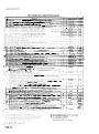
Furnished Ancillary Equipment List is as follows.
2.02
Table A-Basic Configuration
Description
Q'tv
Displaying Unit
I
Sending Unit
I
Furnished Ancillary Eq~~iprnent
I set
Table B-Furnished Ancillary Equipment List
No.
v/
I/
1
1
1
1
1
5
Coaxial Low Pass Filter. 6GHz. Tvpe NOf-F
6
Leveling Cable Assembly .4
7
i
!
8
/ '
!I
J$
.
V'
1
J
'
v
1
IF Power Head, 10 to 30051Hz. 7511 WECo 440*
4
3
9
r
1
I
I
I
i
/
1
1
1
RFPOWERHEAD
DIRECTIONALDETECTOR
MA62A
MA63A
1
FA6
1
I
2.5rn
Cable. BNC(Xt) to BNCIM)
0.13111
I
FA7-2
Power Head Cable (IF) black
2.5m
1
FA8-1
Po\ver Head Cable (RF) preen
2.5m
1
FA8-2
2
FA9
Cable, WECo 440- to \\LC0 440'
1.5m
AC Power Cord yello\v 7'6"
1
11
Interface Cable between D~splayingUnit and Sending Unit
1
12
Instruction Manuals (Operst~onManual and Servlce jlanual)
13
P.C. Board Removal Tool
1 Self-contained Card Extender
2
1
lset
Fuse (5A)
1
16
Fuse (0.5A)
1
1 Secondary Fuse (10A ... 2, 1.6A ... 3 , 2A ... l i
I
1 set
FA7-1
FA1 1
l ea.
15
17
I
I
I
1
10
14
IF POWER HEAD
Cable, BNCW) to RNCPfi
Note: *WECo 440 or Equivalent
Page 1-2
NOf)
N(?I-F)
1
Model No. or Part No.
Q'W
1 R F Power Head, 0.1 to I I.7GHz. 5 0 a , Type
1 Directional Detector, 3.65 to 11.7GHz
1 Coaxial Low Pass Filter. 4GHz. Tvpe
2
v
\
Descriptions
I
I
B. Options
2.03
(1)
In addition to the basic MRTS ME645A, the following options are available:
Option 003: Conversion to add 2GHz capability
The addition of the 2GHz band is possible both
in the original order or on a retrofit basis.
Furnished Ancillary Equipment for option 003:
(3)
Option 001: Conversion to add 1 lGHz capability
a. Directional Detector (2GHz)
The addition of the 1 lCHz band is possible both
in the original order or on a retrofit basis.
Furnished Ancillary Equipment for option 001 : Coaxial
low pass filter, I lGHz, Type N(M-F), MA7 1A.
1
b. Coaxial low pass filter, 2GHz, Type N(M-F),
MA64A
(4)
(2)
Option 002: Direct RF counting
The available
ancillary equipment list is shown in Table C.
Available Ancillay Equipment:
Direct RF counting can be included only in the
original order.
Page 1-3
Table C-Available Ancillary Equipment (Optional Accessories)
No.
I
2
3
I
I
1
D C t o 1 1.7C;lI~. \JSWR< 1.75.
Typc N(51-I:)
--
I
/
757C-20
A
A
!
757C-30
768-20-SP
I
793F?.I-SP
A
I
1
\f1'53 111
A
1
1
I
1
51P531F
IlP53IA
A
A
Description
(1-W
R I ( i ~ a s ~ ..\tt<~lt~:~r<,r.
il
I 0.%.5dB. ?\\'.
DC to. I I . 7 G l l t , \JS\VR<l.?5.
-
I R I (.i~au~;jl
\r!c~~ti;tr,~r.
-- 20 C0.5dll. I\.'
--
p~
U l Co:iu~:il
. . \ t t ~ ~-r i ~ ! ; 311
~ t ~?>l dr l.< . ?I\.
D(' 11, I l.7(.llr,
-
-I
5
T ! ~ i c N(\f-I:)
I
1
\'S\\'U<!.25,
-.
T!pc Y(4l-1:)
K I ('n;~ui.~I
.\ttsn~l:ltor..2 i l k07SdR. ? 0 \ \ . DC t o 6.SG117. \'S\\'K<1.3.
-~
I
1
Typc -N - 4
p~
RI: CCUYI;L': \ ~ r ~ . i r ! ~ . i rC't~:iti~iilu~isI\
~~!.
i,ari;:hlc 0 r r ZOdl3. 3.65 t o 6.5GHz. Typc N(M-1:)
I
1
Model or Part No.
Note
4
757C-10
A
I
1
-
4
I
,J
18
~ d , , ~ > t ~ ,I.(.,,- 1 7 ~ - 560,
'
r.(.(,
560-
I(,
-
S I f ) ti, \ \ I
.\,litpIcr, T! pc \I I~I t ~ . T\
- pc \ ( I - )
...~-.\d:q)t~,r, I iOo!\, 'T!Lx \ ( \ I ) to Ty)x. N(l,.l
T r ; l i ~ \ ~ t ~ o~ny. p SII
z
) I,,
(',I
-.--
-
A.R?29 \\';lvc$i~idc. VS\\R<1.04.
4G117
2.1
25
Tr.l~iririon.T!pv S i t I it! \\ K 1 5 9 \\':~vcpuide. VS\VR<I.M.
Tr:lil\~tion.7mni c o l l ~ l ~ ~ ctti ?o \\'RI
r
59 \\'avcpi~tds.\'S\t'R<I
6G117 band
0 2 . 6(;11r hand
26
2-
lra11\11ion.l'\. DC
c.
. S i k I 1,) \\'R9O \\ : ~ v c ~ i t i d \.S\\'R<1.04,
I l;~ltcr 70\111/
29
1 In\errioil
1 R e t ~ t r iLl . ~ \ \ > ? h c l l l I 6 4 7 h f t l 1 . 7 5 n )
I 1:ilttr 7011117 I(la P:$\\.\ \ I I.0 440t to 560'
A
A
.A
I
S-LA1014
A
1
B40?1-?!A
A
I
B40\1-7A-SP
A
2
D40Sl-SA
B
I
D40\f-7A-SP
B
C
X 4 0~I - U .~
A
I
I . 0 2 , I l ( - I l d : h:111d
jFJH -i 5 O\ l l l / l 3dli
161
\I l l / l --I ?dR 170\111;.) 3dR f79\1117l 35dB ( 9 0 M t I 7 l
- .t,,
~
I
1-
A
~
X40L-?A-SP
1
Hand Ps%. WFCo 440' t o 560;
I . t h \
\IP537.4
M458A
77
I l G I l / I1:t:id
. .. ---
T ~ . I I ~ ~ ~ I I <~II:III
. ~ I I .~.01111c~.ttlr
t t ~
\\'U90 \\'.~\c$~iicIc.\'S\\'R<
ZX
1
2
--.
~
l
I
?IA41 1.4
i
1.02. 4C;Ilr h ; ~ t i d
A
I
-
~ ~ I I C I
Tr31i\i!h)11.
7111n1<.<~i~lic,.ri,t
111 \\.R?29 \\':lvupttide. \'SWU<
..
-
\IPS3 1G
7
--
3
A
,
7
-
560". t l \cd for I t - P u ~ e Head
r
C;~l~bratin~il
21)
V, 2
-~
I
\daptcr. T!IK
21
p
p
560-
19
,
\
,\;~lptcr. I\
\ll'53lB
1
I
\. f.A. .P .Q.A
,
.
1
I
C
.\
\IA4IOA
.4
\Ii\410R
D
I
5 1 5 6 ,\
I..
I
\I.-45 7.4
E
I
11A4PA
\
I
hIRS4A
A
I
SP2369
2.-..
30
A
jlAS50
A:\37
A
A
ffA59A
\IB23A
A
A or G
-
-
~
~
~
-
--
-
-
- ~-
.
p~~~
St,,1' H.IIIJ
I 1 t < ~ ~ 1 . 4 ~ ; 1Ln\.;>40dR).
17.
- -
T y p c Yi\I-1-1
- -.
.
p~
1
34
,
1
35
36
--
S
~
I I I 4I
d
I
i
e
-
I f - .\rnpltticr. ? to 4 > d l i : ~ d ~ ~ ~ \ t : >~ >l )1l e~ .95MII/.
1
I.latiie.;<<0.3dH.
1 I1
-
-
,
F
Po (\lnx.l>+Sdllm
\\1111 3111 DC C ~ h l c \\
. IC,) 560- t o 560-
Kctitrn
Hrldfc. 55 t o LfO\lll/. Hr~dgcBalance > 55dB. Tc<t p o r t \Vl.Co 440'
I K I K c t ~ l r nLC>\\l i r ~ dg c ?. rc I 1 G l I / . Directivity >44dB. Tcsl p o r t .4PC-7
1 I iucd S l ~ o r t i. f ~ U>l ~Uctur11 1.0~s k f c : ~ \ ~ t r c ~ n eC:~libratic~~i)
iit
I.<lr\
--
--
-
34
4d:iprcr. 7nim tu Type \ ( \ I ) . i f o r I I I .-Uctllrli 1.o.;~ Sle:~sureiiicnrr
'l-?\t b a d I'or l l . \ ~ . \ l . . I>II.L~
IXIII;III;~
pI11g l o :tlli?:tr~>rclip and pick
EI
p
p
27
I
~-
~
-
7
-
Spl11111lpI':ld 7511. L,lr\ h d l l n o r-n -.i ~ ~ ;5~0l . rtl 9 5 \ l t I / . Conncctorc
three
\\'FCo 560'
. ~Port:ihlc
R:I..~. 01\pl3!i11p 1'1111arid S e i i d ~ ~ Ii 'gl i i t 3rc r t i l ~ k c d
I
~
39
Soil P:lck C;trr\ Ins (':t\r.\. h ) r I)~\pl:i).i~ig
I'IIII-I.
Pr~,tcctivc S l l i p ) ~ i ~('.I\L,\.
if 47
I
for Selldine I O i i t - I . !'or .Alisilinry liquipment-l
! o r D ~ r p l n y i ~I
yn -i -t - I . for S c~ ~ d i l(i :gl i ~t - l .l o r A!~siliiir!.
Equipment-l
-~
..~
/ 11. H:~rmo~iii.
I iltcr. \\ lt.(~'(>
440' 10 %0*. I'LIx.;
H;~iid170 t o 74.1\1II1. Lox.;<0.5dA.
I.':
C;.
Page 1-4
3
--
A
A
3
I
F:
'
F
\IAS 10.4
To be p r o v ~ d e d\vtth order5 tor TD-3. e3rly vintage.
T o he provided ar reqi~estcd.
T o he providcd ,I\ reque\tcd.
\\'ECo 560. 440. 358. 477 or Eqll~vdllent
4
3.
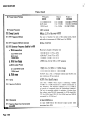
SPECIFICATIONS
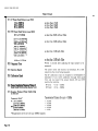
Table D-Specifications
1.
POWER METER
(1) Absolute Measurement Accuracy
Within +0.5dB, when using the 7 5 R power head over the
range 1 0 t o 300MHz o r the 5 0 R power head over the
range IOOMHz t o 11.7GHz, including the effects of
ancillary equipment.
(2) Accuracy of Power Meter Alone
Within k0.2dB
(3) Harmonics
Capable of maintaining its accuracy when measuring power
at +IOdRm in the presence of second harmonics down
12dB from the measured signal.
RF band (50R) with low pass filter:
500 t o 700MHz
700 t o lOOOMHz
2.11 t o 2.18GHz
3.65 to 4.25GFIz
5.8 to 6.5GHz
10.6 t o I 1.7GHz
IF band (75R) with low pass filter:
70MHz and 74.1 MHz
(4) Range
+ I 0 t o -30dRm without external pads or amplifiers.
(5) Resolution
0.OldB
(6) Overload Rating of the Power Head
Capable of withstanding continuously +20dBm without
burnout or change in characteristics.
(7) Power Head Marking
Marked as t o the maximum average power the power
head are capable of withstanding without burnout or
change in characteristics.
Displaying unit: "+20dBm MAX"
Power head: "CAUTION-MAX INPU r POWER +20dBmV
(8) Readout
Digital: A 4 digit LED display in dBm.
Analog: 12dB full scale (calibrated in 0.5dB increments)
peaking meter.
(9) Stability
Maximum drift of k0.1 dB for +10 t o -25dBm and ?0.15dB
for -25 to -30dBm, over a 2 hour period at 24OC room
temperature.
(10 ) Drift Correction
Automatic with front panel pushbutton.
Page 1-5
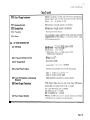
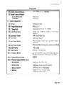
Table D (Cont)
-
-
(11) IF Power Head Return Loss (75R)
no less than 25dB
no less than 30dB
no less than 20dB
14 to 50MHz
50 to 95MHz
95 to 300MHz
(12) RF Power Head Return Loss (50R)
no less than 20dB without filter
0.1 to 11.7GHz
2.1 1 to 2.18GHz
3.65 to 4.25GHz
5.8 to 6.5GHz
I
no less than 23dB without fiter
500 to 700MHz
700 to lOOOMHz
2.11 to 2.18GHz
3.65 to 4.25GHz
5.8 to 6.5GHz
no less than 15dR with filter
10.6 to 11.7GHz
no less than 13dR with filter
(13) Response Time
Within 2 seconds after applying the input power to be
measured.
(14) Spurious Signals
The power meter and head do not introduce AC or DC
signals into the circuit being measured.
(15) Calibration Signal
The IF calibration source is energized or deenergized independent of any meter calibration through front panel
CAL and rear panel CAL power Switch, ON and OFF
push-button switches.
(16) Swept Amplitude Response Range of
Power Head (Oscilloscope display only)
IF band:
RF band:
+12 to -12dBm
+10 to -1OdBm
(17j Detector Flatness (Power head acting
as detector)
Frequency Band *
Transmission Flatness for up to + I OdBm
IF: 50 to 95MHz
+ .025dB
+ .025dB
+ .025dB
* .025dB
+ .05dB
* Requirements t o be met over any 40MHz segment.
Page 1-6
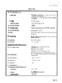
Table D (Cont)
(18) Detector (Power head) Harmonic Distortion
2.
3.
The IF detector flatness is less than *0.03dB/?20MHz
with second harmonic distortion 25dB below the measured
signal (with low pass filtering for RF).
DIGITAL VOLT METER
(1) Ranges
kO.l t o +100VDC and + l o 0 to +999VDC
(2) Accuracy
+0.3V on lOOV range and +3V o n 999V range.
RETURN LOSS CIRCUITRY
The return loss i s measured combination
with IF and RF Return Loss Bridges.
(1) Ranges (oscilloscope display only)
IF (75R)
0 t o 20dB
10 t o 30dB
2 0 t o 40dB
RF (50R)
0 t o 20dB
10 t o 30dB
(2) Test Signal Power
1OdBm nominal
IF (75Q)
-
RF (50R)
-5dBm nominal
(3)Accuracy
IF R.L. measurement accuracy is (for test terminal of
WECo 560-without adapter):
within I d B for 1 0 to 30dB R.L.
within 2dB for 0 to IOdB R.L. and 3 0 t o 40dB R.L.
Return loss of adapter WECo 3 5 8 t o WECo 560 (MP533A)
is more than or equal t o 40dB.
R F R.L. measurement accuracy is within 3dB for up t o
25dB and visible on the display for up t o 30dB.
4.
SPECTRUM ANALYZER
(1) General Requirement
Provides a visual indication of the spectra of the total IF
bands of fo +32MHz with a dynamic range of over 70dB.
(2) Scan Width Selection IF Bands
(fo = 70MHz & 74.1 MH7.
fo i s centered on display)
klMHz
+5MHz
+15MHz
-132MHz
Page 1-7
Table D (Cont)
-
5.
(3)Dynamic Range
70dB (+I MHz)
60dB (all other scan widths)
1OdB sensitivity /cm of deflection
(4) Spurious
-60dBm (all scan widths except +32MHz; Spurious at
+32MHz is -50dBm)
(5) Reference Selection
OdBm only
(6) XY Plotter Output
Compatible with existing Baseband Analyzer (S/A)
(7) Input Buffer Amplifier
Limits L.O. Leakage out at Input Port
(8) Sweep Speed
1Oms/cm
DISPLAY CIRCUITRY
(1) Vertical External Input
BNC Connector
(2) Common Mode Rejection
At least 50dB on vertical external input
(3) Vertical Sensitivity (a to d)
(Type of Signal Input)
dB sensitivity per cm of deflection
a. IF (Detected)
0.05,0.1, 0.5 and 1.OdB
b. RF (Detected)
0.1,0.5 and l .OdB
c. RF & IF Return Loss
2.5dB
d. External DC (Detected)
SOmV/cm of deflection
(4) Vertical Bandwidth
Fixed at DC to lOkHz and no less than 3lOkHz for the
external input.
(5) Input Network (both Vertical and
Horizontal)
1MO (+lo%) shunted by not more than 50pF.
(6) Horizontal External Input
BNC connector; single ended DC Coupled such that a
positive going voltage causes beam deflection to the right.
(7) Horizontal Sensitivity (including
Adjustable over the range from 0.5V to 2.OV per cm.
external input)
(8) Blanking
(9) Z
- Axis
Blank on an external +3V pulse, regardless of intensity
(TTL compatible)
BNC Connector accessible from the rear panel.
Page 1-8
Table D (Cont)
(10) Out of Range Indication
Bright line display on CRT and LED (Vertical Sensitivity)
lamp blink on and off when the power head input level is
from 1 3 to -39.99dRrn +0.2dR.
(1 1) Horizontal Axis
Divided into 1 0 equally spaced 1cm divisions.
(12) Vertical Axis
Divided into 8 equally spaced Icm divisions.
(13) Faceplate
Shatterproof safety-shield.
(14) Bezel
Accommodates camera adapters from major scope camera
suppliers such as HP Models C01-10369A. 10369A and
197A and Polaroid CU-5.
6.
R F SWEEP GENERATOR
(1) CW Mode
2GHz band: 2.1 1 to 2.1 8GHz (option 003)
4GHz band: 3.65 to 4.25CHz
6GHz band: 5.8 to 6.5GHz
1 lGHz band: 10.6 to 11.7GHz (option 001)
(50R output impedance)
(2) Frequency Setting Accuracy
Within +I x lo-'
(3) AF Sweep Mode
Fixed sweep width
sweep width: +2, + l o , + I S , +20MHz
(4) Leveled Power Output
Continuously adjustable over the following ranges:
OdBm to +lOdRm ( 2 , 4 , 6 G H z bands)
OdBm t o +SdBm (1 I GHz band)
(5) Cable (RF Oscillator to Directional
Detector)
Cable assembly is encased in a common sheath.
(6) Power Output Continuity
The Power Output does not vary more than 0.2dB when
switching from a swept mode t o the OV mode.
in 2 and 4GHz bands, AF = t 1OMHz
in 6GHz band, AF = +I 5MHz
in 1 lGHz band, AF = 220MHz
(7) Power Output Stability
Within +0.05dB over any 1 5 minute interval and within
+O.ldB over any continuous 2 4 hour period.
-
Page 1-9
ASAC-104-201-501
Table D (Cont)
(8) Power Output Flatness
(9) Sweep Frequency
Frequency
Band
Output
Power
2 and 4GHz bands
6GHz band
1lGHz band
0 to +IOdBm
0 to +10dBm
0 to +5dBm
Output
Flatness
+0.025dB/+lOMHz
+0.025dB/+20MHz
+0.05dB/+20MHz
46Hz nominal
(10) Sweep Linearity
Within ?2.5% of the sweep width
(11) RF Frequency Markers
One pair of markers for each of the sweep modes, switch
selectable in increments of 1MHz from 0 to 20MHz.
(12) RF Frequency Markers Accuracy
Within +0.005%
(13) RF Generator Frequency Stability (a to d)
a. With temperature
2 and 4GHz bands
6G Hz band
l l G H z band
b. With line voltage
Maximum change in frequency is:
- + 1 6 0 k ~ z /from
" ~ 0°C to 50°c
+200kHz1°C from O'C t o 50°C
+ 1.~MHz/"Cfrom 0°C to 50°C
51 MHz max. for AC 103 to 127V variation
c. With output Power
2,4 and 6GHz bands
1lGHz band
d. With time
(14) Aging
(15) Spurious Radiation
--
+0.012% max. over a 15-minute interval and *0.03% over
any continuoils 24 hour period.
+0.03% for at least 10 years.
Less than -50dBm when output is delivering +lOdBm
(+5dBm for 1lGHz band) into a resistive termination at
any frequency. The harmonic radiation up t o 11.7GHz is
no greater in magnitude than the fundamental radiation.
The unit is measured radially for radiation 12-inches from
the cabinet using WR-430 waveguide for 2GHz band,WR229 for 4GHz band, WR-159 for 6GHz band and WR-90
waveguide for 1 IGHz band.
(16) Harmonics
At least 40dB down.
(17) Spurious Signal (non harmonically
At least 64dB below the selected output power when
terminated into 50Q.
related)
-
+lMHz max. for OdBm to +10dBm change
+IMHz max. for OdBm to +5dBm change
-
Page 1-10
Table D (Cont)
(18) Residual Amplitude Modulation
At least 40dB below the output signal.
(19) Residual Frequency Modulation
2,4 and 6GHz bands
11GHz band
7.
30kHz peak
5OkHz peak
IF SWEEP GENERATOR
(1) CWMode
70MHz and 74.1MHz
(2) Frequency Setting Accuracy
Within +2 x
(3) AF Sweep Mode
Fixed sweep width f 2 , ? l o , f 1 5 , f20MHz
(4) Leveled Power Output
Variable from -70dBm
impedance.
(5) Continuously Variable
1OdB range ( t l OdBm max.)
(6) Step Variable
70dB range, 1dB steps
(7) Power Output Stability
Within +0.05dB/15 minute interval and within tO.ldB/24
hour period.
(8) Power Output Flatness
Within +0.025dB at AF sweep modes between 0 and +10dBm
(9) Sweep Frequency
46Hz nominal
to +lOdRm at a 75fl output
(10) Sweep Linearity
Within +2.5% of sweep width
(11) IF Frequency Markers
One pair of markers for each of the sweep modes switch
selectable in increments of I MHz between 0 and 20MHz.
(12) 1 F Frequency Markers Accuracy
f0.005%
(13) IF Generator Frequency Stability (a to d)
a. With tempeature
+30kHz m a x . 1 ' ~ at O°C to 50°c
b. With line voltage
flOkHz max. for AC 103 to 127V variation
c. With output power
+lokHz max. for 0 to +10dBm change
d. With time
+SokHz max. over a 1 5 minute interval
+100kHz max.124 hour period
Page 1-11
Table D (Cont)
8.
(14) Spurious Radiation
The radiation from the fundamental frequency from the
IF oscillator is no greater than -100dBm when the
output is delivering +IOdBm into a resistive termination at
any frequency. The harmonic radiation up t o 300MHz
shall be no greater in magnitude than the fundamental
radiation. The unit is measured radially for radiation with
a suitable field intensity meter, excited by a simple
resonant dipole placed no more than 12 feet and no less
than 8 feet from the finished chassis, with no additional
shielding.
(15) Harmonics
The magnitude of the second and third harmonic of
50(54.1), 60(64.1), and 70(74.1)MHz present in the
generator output is measured by means of a suitable
selective analyzer. In addition, the second harmonic of
80(84.1) and 90(94.1)MHz is measured and their magnitudes relative to the fundamental, is no greater than the
following:
Fundamental, f, MHz
2f
-
SO(54.1)
60(64.1)
70(74.1)
80(84.1)
90(94.1)
-40dB
4OdB
4OdB
40dB
40dB
f
3f
f
-
-40dB
-40dB
4OdB
-
-
(16) Spurious Signal (non harmonically
related)
At least 70dB below selected output power when terminated in 75S2
(17) Residual Frequency Modulation
No greater than 1.5kHz peak
(18) Slope Adjusting Range
No less than +O.ldB slope over 50 to 90 and 54.1 to 94.1
MHz range, front panel adjustment.
(19) Frequency Shift
The 70 and 74.1MHz CW frequencies are slufted by
+300kHz and -300kHz for C/I measurements.
FREQUENCY COUNTER
(1) Frequency Range
14 to 300MHz directly and without prescaling.
(2) Input Network
At least 1MS2 shunted by less than 20 p F (14 to 135MHz)
and 50S2 (14 to 300MHz) switchable.
(3) Input Level
15mV to SVrms without need for level adjustment.
(4) Accuracy
?1 count +Time Base oscillator stability.
Page 1-12
Table D (Cont)
-
(5) Time Base Stability (a to c)
a. Short term
a) At least 5 x
(after 15 minutes warm up) for a
minimum of 2 hours and
b) A t least 5 x
per day after 24 hours continuous
ope ration.
b. Aging
*l x lo-" per year
c. With line voltage
1x
for AC 103 to 127V
(6) Time Base Frequency
1OMHz
(7) Time Base Output
1V peak-to-peak minimum across 50R (TTL compatible)
(8) Time Base Adjustment
A minimum of k 5 x 1CJ8
(9) Oven
Crystal oven remains on when the front panel power switch
is turned off.
(10) Sample Rate
Minimum 0.08 seconds. Variable by steps of 0.08. 0.8. 2
seconds and hold.
(11) Gate Time
10, 1 and 0.1 seconds
(12) Resolution
0.1, 1 and 1OHz
RF Measurements (Option 002) (13) to (17)
9.
(13) RF Frequency Range
2GHz band: 2.1 1 to 2.1 8GHz (option 003)
4GHz band: 3.65 t o 4.25GHz
6GHz band: 5.8 to 6.5GHz
1 l G H z band: 10.6 to 1 1.7GHz (option 001)
directly without manual or external prescaling or tuning.
(14) Input Network
Over the specified frequency range the input impedance is
a nominal 50R.
(15) Input Connector
Type "N" connector.
(16) Input Level
-20dBm to +7dBm
(17) Resolution
1kHz
ENVIRONMENTAL
(1) Specification Compliant Ranges (a to c)
a. Temperature
0°C to +50°C
b. Altitude
0 to 10000 feet above sea level
c. Relative humidity
10% to 95%
Page 1-13
Table D (Cont)
-
(2) Storage Range
-40°C t o +60°C
(3)Warm up Time
a) 1 5 minutes from turn-on from an ambient of 2 4 ' ~and
b) 6 0 minutes from turn-on in an ambient of 2 4 " ~after
being brought in from an environment of -1 8°C.
(4) Burn-in
9 6 hour operational burn-in at +50°C
(5) AC Input
Single phase 1 15 *12V, 60Hz, <
= 250VA power source.
(6) Shock and Vibration
MIL-STD-810J3, Method 514.7 Procedure X, Sinusoidal
Cycling only.
a. Shock
At room ambient conditions per MIL-STD-810B 20g, 10
milliseconds, sawtooth ascending pulse, two repetitions in
each direction of three mutually perpendicular axis (12
drops).
b. Vibration
0.25 inches displacement, D.A., 5 t o 9Hz and 1.0g from
9 t o 100Hz.
A sweep rate of two minutes per octave ascending and
descending in each of three mutually perpendicular axis.
10. MECHANICAL & MISCELLANEOUS
(1) Weight (including each carrying case)
Displaying Unit
Sending Unit
Ancillary Equipment
less than 4 0 Ibs. (<I 9kg)
less than 4 0 lbs. (<19kg)
less than 4 0 lbs. (<19kg)
(2)Dimensions (each unit)
16.8in.(426mm)W x 17,8in.(450mm)D x 5.7in.(145mm)H
(except for controls, handles, etc.)
(3) AC Power Cord
The 7'6" detachable power cord is yellow and equipped
with a NEMA 5-1 5P ground plug.
(4) Line Fuses
are accessible from the rear panel.
( 5 ) Ground Loop
The MRTS does not exhibit any ground loop problems
when in a back-to-back configuration. ( R F & IF flatness
requirements are met). r
(6) N Type Connectors
Internal dimensions and tolerances of mating surfaces meet
MIL-C-39012.
N connector shells and the nut on male connectors are
stainless steel.
Page 1-14
Table D (Cont)
.-
( 7 ) Repeater Bay Interfaces
The MRTS interfaces repeater bays with N-type connectors
for 50R test points, and WECo 560A, or approved
equivalent, jacks for 75R test points.
(8) Portable Test Rack
A collapsible mobile rack is available to support the MRTS.
It does not restrict a view of the MRTS while in a kneeling
position making adjustments on a repeater bay near floor
level.
Page 1-15
15 Pages