1
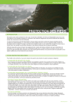
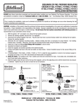
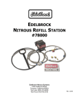
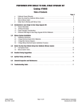
FIREWALL FORWARD FUEL LINE KITS
For 1996-2000 Honda Civic Equipped with B-Series Engine
Catalog #641570, 641573
INSTALLATION INSTRUCTIONS
PLEASE study these instructions carefully before beginning this installation. Most installations can be accomplished with common tools and
procedures. However, you should be familiar with and comfortable working on your vehicle. If you do not feel comfortable performing this installation,
it is recommended to have the installation completed by a qualified mechanic. If you have any questions, please call our Technical Hotline at:
1-800-416-8628, 7:00 am - 5:00 pm, Pacific Standard Time, Monday through Friday or e-mail us at [email protected].
IMPORTANT NOTE: Proper installation is the responsibility of the installer. Improper installation
will void your warranty and may result in poor performance and engine or vehicle damage.
DESCRIPTION: This Russell Performance Firewall Forward Fuel Line kit includes all necessary parts to replace your factory rubber fuel lines from the
fuel filter to the fuel rail and from the fuel rail to the factory steel return line with a high performance Edelbrock aluminum fuel rail, Proflex/Twist-Lok,
or Proclassic hoses, and AN fittings. The kit is designed to fit 1996-2000 Honda Civic chassis equipped with a Honda DOHC B-Series engine, and will
provide increased fuel flow for high performance applications. Kit #641570 features Proflex/Twist-Lok hoses and red and blue anodized fittings, while
kit #641573 features Proclassic hose and fittings with a black and clear finish.
KIT CONTENTS:
❑
❑
❑
❑
❑
❑
❑
❑
❑
❑
❑
1
1
5ft
3ft
5ft
3ft
1
2
1
1
1
Fuel Rail. High Flow, Honda B-Series Engines (PN 4796)
Adjustable Fuel Pressure Regulator (PN 1728)
Proflex Hose (-6AN) (641570 Only)
Twist-Lok Hose (-4AN) (641570 Only)
Proclassic Hose (-6AN) (641573 Only)
Proclassic Hose (-4AN) (641573 Only)
Honda Banjo to -6AN Male Adapter Fitting
Straight Hose End (-6AN)
90° Swivel Hose End (-6AN)
45° Swivel Hose End (-6AN)
Straight Twist-Lock Hose End (-4AN) (641570 Only)
❑
❑
❑
❑
❑
❑
❑
❑
❑
❑
❑
1
2
1
2
2
1
1
1
1
2
6
Straight Hose End (-4AN) (641573 Only)
#4 Hose End Cover (Red, 641570 Only)
#4 Hose End Cover (Polished, 641573 Only)
-8AN to -6AN Adapter Fittings (with o-rings)
-6AN Dry-Sump Fittings (with o-rings)
-6AN Block-Off Plug (with o-ring)
-6AN Female to -4AN Male Coupling
-6AN Female Coupling Nut
#4 Hose Clamp
12mm Aluminum Crush Washers
Tie-Wraps
TOOLS REQUIRED:
❑
❑
❑
Hand Tools, Standard and Metric
Standard and Metric Allen Keys
AN Wrenches
❑
❑
❑
AN Fitting Assembly Lubricant
Liquid Teflon Thread Sealant
Fuel Pressure Gauge (For Fuel Pressure Adjustment)
CAUTIONS AND WARNINGS
WARNING: EXPOSED FUEL AND OIL WILL BE PRESENT DURING THIS INSTALLATION. WHEN WORKING AROUND
GASOLINE OR OIL, ALWAYS WORK IN A WELL VENTILATED AREA, AND KEEP ALL OPEN FLAMES, SPARKS, AND OTHER
SOURCES OF IGNITION AWAY FROM THE WORK AREA. FAILURE TO DO SO CAN RESULT IN A FIRE OR EXPLOSION.
MAKE SURE TO DISCONNECT YOUR BATTERY TO AVOID THE POTENTIAL FOR SPARKS IN THE WORK AREA!
NOTE: Certain Honda vehicles have security protected audio systems. If your vehicle is equipped with a factory audio system, be
sure to have the security code written down prior to disconnecting the battery. See Honda Service Manual for additional details.
WARNING: SOME PROCEDURES IN THIS INSTALLATION MAY REQUIRE THE VEHICLE TO BE RAISED ON JACKSTANDS OR A LIFT. WHEN
RAISING A VEHICLE, MAKE SURE THE VEHICLE IS ON LEVEL GROUND AND SUPPORTED SECURELY BY JACKSTANDS.
NEVER WORK UNDER A VEHICLE THAT IS SUPPORTED BY A JACK ONLY!
Catalog #641570, 641573
Rev. 5/07 - RS/mc
Page 1
©2007 Edelbrock Corporation
Brochure #63-641570
BEFORE BEGINNING INSTALLATION
BEFORE BEGINNING: Someone who has a basic knowledge of automobile repair and modification and is familiar with and comfortable with working
on their vehicle can accomplish the mechanical installation of this kit using common tools and procedures. However, this kit is designed to allow you
to custom fit the fuel lines to your application, and will require that you cut hoses to fit and drill holes for Fuel Pressure Regulator mounting. If you do
not feel comfortable with any of the steps listed below, please consult a qualified professional installer. Make sure to read the instructions provided
with the supplied fuel rail and fuel pressure regulator. These will be referenced throughout this instruction sheet.
AFTER INSTALLATION, BEFORE STARTING THE VEHICLE: ALWAYS make sure to check for any leaks BEFORE starting the vehicle. Reconnect the
battery and turn the ignition key to the “on” position. This will activate the fuel pump and pressurize the fuel system. If any leaks are present, turn
the ignition “off”, disconnect the battery, and make the necessary corrections before continuing.
INSTALLATION PROCEDURE
DISASSEMBLY AND FUEL RAIL INSTALLATION
5.
Remove the banjo bolt from the fuel filter and disconnect the fuel
supply line from the fuel filter. Using a small, fuel safe container,
allow the excess fuel to drain from the fuel line and fuel rail.
1.
Make sure the vehicle is on level ground, and the gear selector is in
“Park” or in 1st gear. Set the parking brake or chock the wheels.
2.
Disconnect the battery negative terminal. See note on page 1
regarding Honda/Acura security protected audio systems.
6.
Disconnect the factory fuel return line from the steel tubing on the
firewall. Use rags or a small, fuel safe container to catch any spills.
3.
Thoroughly clean the area surrounding the fuel injectors and the fuel
rail. This will prevent debris from entering the fuel system or the
intake manifold upon fuel rail removal.
7.
Disconnect the wiring harness from the fuel injectors and from the
fuel rail. If your vehicle is equipped with a purge valve, disconnect
the wiring from the purge valve.
4.
Relieve any residual fuel pressure in the fuel system. Remove the
fuel filler cap, then relieve fuel pressure by loosening the banjo bolt
connecting the fuel line to the fuel filter. Place a shop towel or rag
over the wrench while loosening the banjo to soak up any fuel spray
(See Fig. 1). When loosening or tightening the banjo bolt on the
fuel filter can, use a 19mm wrench of the hex of the fuel filter can
to counteract the torque of loosening or tightening the banjo bolt.
This will prevent the fuel filter can and bracket from being
improperly loaded during loosening or tightening at the banjo bolt.
If your vehicle has a special banjo bolt at the fuel filter, which has a
service bolt in the top of the banjo bolt, use a 6mm box end wrench
to loosen the service bolt at the fuel filter while holding the banjo
bolt with another wrench. Keep the banjo or service bolt loose until
all pressure is relieved.
8.
Remove the vacuum line from the factory fuel pressure regulator.
Refer to the instructions supplied with the 4796 fuel rail, and remove
the fuel rail, factory fuel pressure regulator, supply line, and return
line from the vehicle as one assembly. Use care when separating
the fuel rail from the fuel injectors.
9.
Install the supplied -8AN to -6AN Adapter Fittings (with o-rings) into
the fuel rail using a bit of o-ring lube on the o-rings. Install the 1/8
NPT pipe plugs (supplied with fuel rail) if the gauge ports are not
being used (see fuel rail instructions). Always use liquid teflon
thread sealant on pipe threads.
10. Inspect the injectors and transfer them to the new fuel rail as
described in the fuel rail instructions.
11. Install the fuel rail / injector assembly on the intake manifold as
shown in the fuel rail instructions.
FUEL PRESSURE REGULATOR MOUNTING:
1.
Install the provided fittings into the fuel pressure regulator (See Fig.
2). Install one -6AN Dry Sump Union in the inlet port and one in the
return port (located at the bottom of the regulator). Install the -6AN
block off plug in the fuel outlet port of the regulator. Slip the -6AN
Female coupling nut over the -6AN female to -4AN male coupling.
Install this assembly over the -6AN dry-sump fitting previously
installed in the return port of the regulator. Install the vacuum fitting
supplied with the regulator in the port on the top half of the
regulator. Install the pressure adjusting screw and jam nut at the
top of the regulator. See the instructions provided with the regulator
for more information.
Figure 1 - Relieving Fuel Pressure at Fuel Filter
Catalog #641570, 641573
Rev. 5/07 - RS/mc
Page 2
©2007 Edelbrock Corporation
Brochure #63-641570
Adjusting Screw.
Locknut and Washer
Vacuum
Fitting
Figure 4 - Regulator Mounted on Firewall
-6 AN Block
Off Plug
6.
-6 AN DrySump Fittings
Install the factory fuel pressure regulator vacuum line onto the fitting
on the fuel pressure regulator. You may need to replace or extend
this line, depending on where you are mounting the regulator.
FUEL LINE AND HOSE END PREPARATION:
Figure 2 - Fuel Pressure Regulator Fitting Placement
2.
3.
Determine a location in the engine compartment to mount the fuel
pressure regulator. Make sure it is close enough to the factory steel
return line that you will have enough -6AN hose to reach from the
fuel filter to the fuel rail and from the fuel rail to the regulator. We
chose a location on the firewall.
1.
Measure the -6AN hose and determine the lengths needed to reach
from the fuel filter to the fuel rail and from the fuel rail to the fuel
pressure regulator. Mark the location to be cut and wrap the hose
tightly with masking or electrical tape at this point. Make sure to
use enough hose to prevent the possibility of the hose kinking after
assembly.
2.
Clamp the hose loosely and position the cut line at the edge of the
vice. The best way to cut is with cutting wheel or a hacksaw with
two blades opposing one another. Remove the tape when you are
finished cutting. Proclassic hose may be cut using a utility knife.
3.
Locate the hose ends to be used in your installation. For the fuel
filter to fuel rail supply line, use one -6AN straight hose end at each
end of the line. For the fuel rail to fuel pressure regulator line, use
one 45° swivel hose end and one 90° swivel hose end.
NOTE: The instructions here describe the hose end locations
used for our particular installation. You may use the supplied
hose ends in any location necessary for your configuration.
4.
Hose End Assembly:
NOTE: Use fitting assembly lube when assembling hose ends.
Use AN wrenches if available, and DO NOT OVERTIGHTEN
FITTINGS. See Russell catalog or contact the Edelbrock Tech
Line for details.
A. Unscrew the socket of the hose end from the nipple. Hold
the socket carefully in a vice using soft jaws and insert the
hose into the socket by turning it counter-clockwise. The
hose will stop at the bottom step of the socket.
To mount the regulator in this location you will need to remove the
cowl cover (See Fig 3).
Figure 3 - Cowl Cover Removed
4.
5.
Following the instructions provided with the fuel pressure regulator,
use the provided bracket, and mark the location to drill the mounting
holes.
Using appropriate hardware (sheet metal screws, or bolts & nuts
available through your local hardware or auto parts store), mount the
fuel pressure regulator to the bracket, and the regulator/bracket
assembly to the firewall (See Fig. 4).
NOTE: You may need to bend/modify the supplied bracket in
order to mount the fuel pressure regulator in your desired
location.
Catalog #641570, 641573
Rev. 5/07 - RS/mc
Page 3
B.
Position the nipple assembly of the hose end in the vice
using soft jaws. Apply assembly lube to the threads of the
socket as well as to the nipple assembly.
C.
Start the socket over the nipple by hand to ensure correct
alignment of threads and tighten as far as possible by
hand. Finish with the correct AN wrench until it reaches
the nipple hex or when there is no more than 1/16" gap
between the nipple/socket assembly. Be sure to wash and
pressure test the assembly before using.
©2007 Edelbrock Corporation
Brochure #63-641570
5.
Determine the length of -4AN (Twist-Lok or Pro-Classic) hose
required to reach from the fuel pressure regulator to the factory
steel fuel return line. Measure and cut the hose making sure the
hose will not be kinked after installation.
6.
Slip the -4AN Twist-Lok hose end cover over the Twist-Lok Hose.
The tapered end of the cover should face away from the end of the
hose. Insert the -4AN Twist-Lok hose end into this end of the line
and slide the hose end cover up to the hose end. For Proclassic
hose, assemble the the -4AN hose end on one end of the hose as
described in step 4 above.
7.
Slip the #4 hose clamp cover and then the #4 hose clamp, over the
other end of the -4 hose, but do not tighten.
ASSEMBLED FUEL LINE INSTALLATION:
1.
Install the Honda banjo to -6AN male adapter fitting to the
assembled fuel filter to fuel rail supply line. Install the banjo end to
the fuel filter using the factory banjo bolt and the supplied 12mm
crush washers. Use one washer on each side of the banjo fitting
(See Fig. 5).
Figure 7 - Fuel Rail to Regulator Line
4.
Install the hose end side of the -4AN hose onto the -4AN coupling
on the return port of the fuel pressure regulator. Slip the end with
the #4 hose clamp onto the factory steel return line. Slide the #4
hose clamp over the end of the hose and tighten around the end of
the factory steel return line. Slide the #4 hose clamp cover over the
clamp.
5.
Make sure all connections are tight. Check the overall fuel line
routing, and using the provided tie-wraps, secure the fuel lines away
from any heat sources if necessary (See Fig. 8).
NOTE: The instructions above describe the hose end locations
used for our particular installation. You may use the supplied
hose ends in any location necessary for your configuration.
Figure 5 - Banjo Fitting Installation
2.
Install the -6AN straight fitting end of the fuel rail supply hose to the
inlet side of the fuel rail (See Fig. 6).
Figure 8 - Overall Fuel Line Routing
Figure 6 - Fuel Rail Inlet
3.
FINAL CHECKS:
Install the 90° hose end side of the fuel rail to fuel pressure regulator
line onto the fuel rail’s outlet end. Attach the 45° hose end side of
this line onto the -6AN dry-sump fitting on the inlet side of the fuel
pressure regulator (See Fig. 7).
Catalog #641570, 641573
Rev. 5/07 - RS/mc
1.
Reconnect the battery negative terminal and check for leaks. Refer
to the “AFTER INSTALLATION, BEFORE STARTING VEHICLE” section
on page 1 for details. Remember to enter your audio system
security code if so equipped.
2.
Adjust fuel pressure to the desired level. Refer to the instructions
provided with the fuel pressure regulator for proper adjustment
procedure.
Page 4
©2007 Edelbrock Corporation
Brochure #63-641570
NOTES
Catalog #641570, 641573
Rev. 5/07 - RS/mc
Page 5
©2007 Edelbrock Corporation
Brochure #63-641570
®
Russell Performance • A Division of Edelbrock Corporation
2700 California St. • Torrance, CA 90503
Tech-Line: 1-800-416-8628 • E-Mail: [email protected]
Catalog #641570, 641573
Rev. 5/07 - RS/mc
Page 6
©2007 Edelbrock Corporation
Brochure #63-641570