1
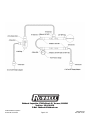
FORD 5.0L EFI FIREWALL FORWARD RUSSELL
PLUMBING KIT
Catalog #641550
INSTALLATION INSTRUCTIONS
Please study these instructions carefully before installing your new complete fuel system kit. If you have any questions, please call
our Technical Hotline at: 1-800-416-8628, 7:00 am to 5:00 pm, Monday - Friday, Pacific Standard Time or e-mail us at
[email protected].
TOOLS & SUPPLIES RECOMMENDED
KIT CONTENTS
❑1
❑3
❑1
❑1
❑2
❑1
❑6
❑ 10 ft.
❑3
❑1
❑4
❑1
❑1
❑1
❑1
Fuel Pressure Regulator Kit #1728
3/8” NPT x -6 AN male adapter
3/8” NPT x -6 AN male adapter w/ 1/8” NPT port
Mustang 5.0 fuel rail kit
-6 AN dry sump union
-6 AN plug
Tie wraps
-6 hose
-6 AN Straight hose end
-6 AN 45° Swivel hose end
-6 AN 90° Swivel hose end
-6 AN to Ford Pressure side fitting
-6 AN to Ford Supply side fitting
Assembly lube/sealant kit
0 - 100 psi fuel pressure gauge
❑ Basic hand tools
❑ AN Wrenches
❑ Drill motor & bits
❑ EFI fuel line disconnect tool
❑ Miscellaneous hardware for mounting components
(including nuts & bolts)
WARNING!!!
Gasoline and gasoline fumes are extremely
flammable. Work in a well-ventilated area away from
open flames, sparks, or other sources of ignition. Try
to contain gasoline when connections are loosened,
and clean up any spills immediately. Failure to do so
can result in a fire or explosion.
IMPORTANT NOTE:
Proper installation is the responsibility of the installer. Improper installation will void warranty and may result in
poor performance and engine or vehicle damage.
WARNING:
MAKE SURE TO DISCONNECT YOUR BATTERY TO AVOID THE POTENTIAL FOR SPARKS IN THE WORK AREA!
SOME PROCEDURES IN THIS INSTALLATION WILL REQUIRE THE VEHICLE TO BE RAISED ON JACKSTANDS OR A LIFT. WHEN
RAISING A VEHICLE, MAKE SURE THE VEHICLE IS ON LEVEL GROUND AND SUPPORTED SECURELY BY JACKSTANDS.
NEVER WORK UNDER A VEHICLE THAT IS SUPPORTED BY A JACK ONLY!
©2007 Edelbrock Corporation
Brochure No. 63-641550
Page 1 of 4
Catalog #641550
Rev. 10/07 - AJ/mc
BEFORE BEGINNING
Someone who has a basic knowledge of automobile repair and modification and is familiar with and comfortable with working on
their vehicle can accomplish the mechanical installation of this kit using common tools and procedures. However, this kit is designed
to allow you to custom fit the fuel lines and components to your application, and will require that you cut hoses to fit and drill holes
for fuel pressure regulator mounting, junction blocks, etc. If you do not feel comfortable with any of the steps listed below, please
consult a qualified professional installer. Make sure to read the instructions provided with the supplied fuel rail and fuel pressure
regulator. These will be referenced throughout this instruction sheet.
AFTER INSTALLATION, BEFORE STARTING THE VEHICLE ALWAYS make sure to check for any leaks BEFORE starting the vehicle.
Reconnect the battery and turn the ignition key to the “ON“ position. This will activate the fuel pump and pressurize the fuel
system. If any leaks are present, turn the ignition “OFF”, disconnect the battery, and make the necessary corrections before
continuing.
Stock fuel rail disassembly
Russell (Manifold Kit) fuel rail install
1.
Make sure the vehicle is on level ground, and the gear
selector is in park or 1st gear. Set the parking brake or
chock the wheels.
1.
2.
Make sure that the vehicle has cooled down.
3.
Disconnect the negative terminal on the battery.
4.
Thoroughly clean the area surrounding the fuel injectors
and the fuel rail. This will prevent debris from entering the
fuel system or the intake manifold upon fuel rail/injector
removal.
5.
Relieve residual fuel pressure in the fuel system. Remove
the dust cap cover over the Schrader valve located on the
fuel tube leading to the rail. Hold a shop towel or rag
around the valve while relieving the fuel pressure to
prevent any fuel spray.
6.
7.
Attach supplied brackets to the supplied fuel rails using
the supplied hardware. Use thread locking compound.
Note: Install most of the necessary components onto the fuel
rail before installing in vehicle for ease of assembly. Be
sure to use thread sealing compound on NPT threads to
prevent leaks.
2.
Using the supplied 3/8 NPT plug, install into the front end
of the driver’s side fuel rail. This end of the fuel rail will
be located behind the distributor.
3.
Using the EFI coupling release tool, disconnect the fuel
feed and return lines. Use a shop towel or rag to catch any
residual fuel remaining in the factory lines.
Choose a suitable location on the fuel rails for a -3/8 NPT
male to -6 AN male pressure adapter to be installed.
Loosely install the -3/8 NPT male to -6 AN male pressure
adapter into the fuel rail. Mock up the fuel rail with the
pressure gauge installed on the fuel pressure adapter
fitting to check for clearances. After a suitable location
has been determined, correctly install the pressure
adapter fitting and the fuel pressure gauge.
4.
Remove the bolts holding the fuel rail to the intake
manifold.
Install the 3/8 NPT male to -6 AN male fittings into the
rest of the inlets and outlets of the fuel rails.
5.
Depending on which intake manifold is used in
conjunction with this fuel system kit, the fuel rail spacers
(included) might need to be used to properly space the
driver’s side fuel rail from the intake manifold.
6.
Mount the assembled fuel rails onto the intake manifold.
Careful attention should be paid to prevent any damage
to the injector o-rings during installation. Fasten the fuel
rails to the intake manifold using the supplied hardware
or the factory hardware.
8.
Remove the fuel regulator, vacuum hose, fuel rail, and the
fuel injectors.
9.
Inspect and replace the fuel injector o-rings if necessary.
10. You will also need to remove the remaining fuel hard tube
(feed and return) running from the fuel rail to the lower
firewall.
©2007 Edelbrock Corporation
Brochure No. 63-641550
Page 2 of 4
Catalog #641550
Rev. 10/07 - AJ/mc
Fuel pressure regulator install
1.
Find a safe and clean location in the engine compartment
for the placement of the fuel regulator and its mounting
bracket (supplied). In most applications, the best
placement for the regulator is on the firewall. Make sure
that the location will allow access for two hoses, entering
from the side and exiting from the bottom of the regulator.
Note: Some modification to the fuel pressure regulator bracket
may be needed for the correct fitment in your desired
location. Refer to the included fuel pressure regulator
instructions for details.
2.
Following the instructions provided with the fuel pressure
regulator, mark and drill the mounting holes for the fuel
pressure regulator bracket.
3.
Install 2 dry sump fittings (-6 AN) into the inlet and exit
ports of the regulator.
4.
Install the -6 AN plug into the unused inlet port of the
regulator.
5.
Install the vacuum hose from the regulator to the intake
manifold. It might be possible to use your stock vacuum
hose for the regulator depending on the placement of the
fuel pressure regulator.
2.
Determine the hose path and length required for the fuel
hose leading from the EFI supply fitting to the fuel inlet
fitting located on the passenger side fuel rail. Build and
install the hose assembly.
3.
Determine the hose path and length required for the fuel
hose leading from the passenger side fuel rail to the
driver side fuel rail inlet. Build and install the hose
assembly.
4.
Determine the hose paths and lengths required for the
fuel hose leading from the exit of the driver’s side fuel
rail to the inlet of the fuel pressure regulator. Build and
install the hose assembly.
5.
Determine the hose path and lengths required for the
fuel hose leading from the outlet of the regulator to the
EFI return side fitting. Build and install the hose
assembly.
6.
Properly install the fuel pressure regulator to the chassis
at this time.
Final assembly checklist:
6.
Roughly install the fuel pressure regulator onto the vehicle
to facilitate hose assembly installation.
2. Reconnect the negative battery terminal. Turn the
ignition or fuel pump power switch to the “on” position,
but do not start vehicle. Check for leaks.
Russell fuel hose assembly and install
1.
Attach the Russell EFI Ford fittings onto the factory supply
and return lines. This is accomplished by pushing the
proper fittings on to the factory lines until an audible click
is heard. Double check connections by tugging on the
fitting to ensure that the fitting is properly attached to the
factory hard line.
Note:Follow the included hose assembly instructions to properly
build the hose assemblies for the fuel system. Ensure that
the fuel hoses are properly located and installed so as to
prevent damage during the normal operation of the
vehicle. Please note that the instructions below give an
example of how this fuel system can be routed. It is highly
recommended that the installer pre-plan the routing of the
fuel system kit to determine which hose end fittings should
be used for each hose assembly.
©2007 Edelbrock Corporation
Brochure No. 63-641550
1. Make sure all connections are tight. Make sure the fuel
supply and return hoses were not kinked or pinched
during installation. Check for any interferences around
the fuel system hoses and fittings. The use of tie wraps
to secure the hoses is recommended.
Page 3 of 4
3. With the ignition still in the “on” position, adjust the fuel
pressure to the desired level. Refer to the instructions
provided with the fuel pressure regulator for proper
adjustment procedures. Continue to check for leaks.
4. Refer to the instructions provided with the fuel pressure
regulator for additional adjustments after starting the
vehicle.
Catalog #641550
Rev. 10/07 - AJ/mc
Edelbrock Corporation, 2700 California St., Torrance, CA 90503
Tech Line: 800-416-8628
E-Mail: [email protected]
©2007 Edelbrock Corporation
Brochure No. 63-641550
Page 4 of 4
Catalog #641550
Rev. 10/07 - AJ/mc