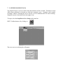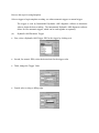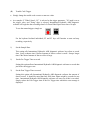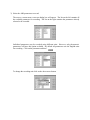
1
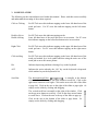
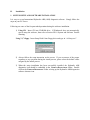
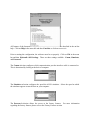
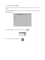
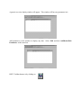
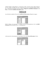
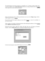
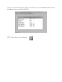
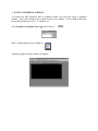
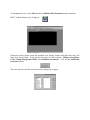
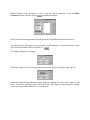
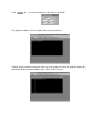
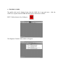
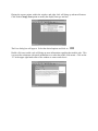
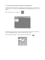
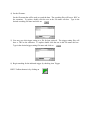
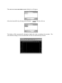
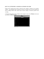
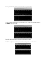
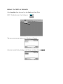
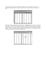
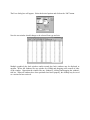
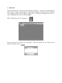
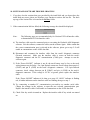
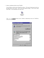
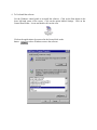
INTERNATIONAL
HYDRAULICABS
Software
®
User’s Manual
International Truck and Engine Corporation®
Copyright
Please read through the License agreement accompanying the software.
The International Hydraulic ABS (ABS) software is written for International Truck and Engine
Corporation and is protected by United States copyright laws and international treaty provisions.
Therefore, you must treat the SOFTWARE like any other copyrighted material. You may,
however, either (a) make one copy of the SOFTWARE solely for backup or archival purposes, or
(b) transfer the SOFTWARE to a single hard disk, provided you keep the original solely for
backup or archival purposes. You cannot copy the written materials accompanying the
SOFTWARE.
This manual is written for International Truck and Engine Corporation by SU Enterprise, Inc.
and is protected by United States copyright laws and international treaty provision.
Third-party brands and names are the property of their respective owners.
The authors assume no responsibility for any errors or omissions which may appear in this
document nor do they make any commitment to update the information contained herein.
Copyright 1999, 2000, 2001, Rev. 2.0
TABLE OF CONTENTS
I.
INTRODUCTION
1. Software Overview
I.1.1
2. System Requirements
I.2.1
3. Nomenclature
I.3.1
II.
INSTALLATION
1. System Setup and Software Installation
II.1.1
III. HOW TO USE HYDRAULIC ABS SOFTWARE
1. Basics
III.1.1
2. Data in Textual Format
III.2.1
3. Data in Graphical Format
III.3.1
4. Trouble Codes
III.4.1
5. ABS Electronic Module Software ID Information
III.5.1
6. Diagnostic Tests
III.6.1
7. Capture Snapshot Data
III.7.1
8. Snapshot Data Recording Replay
III.8.1
9. Sessions
III.9.1
10. System and Software Trouble Shooting
III.10.1
IV. FACTORY FEATURES
1. Factory Features
IV.1.1
I. Introduction
1. SOFTWARE OVERVIEW
The International Hydraulic ABS system has a wide range of failsafe diagnostic capabilities. To
properly diagnosis these failures please follow the instructions outlined in this and other
International manuals. The International Hydraulic ABS diagnostic software provides the
capabilities to
1) Read and display numerous ABS parameters in both graphical and textual format.
2) Read and display International Hydraulic ABS system trouble codes.
3) Provide generic diagnostic information on specific trouble code service.
4) Read and displa y ABS Module ID information.
5) Provide snapshot capability.
6) Provide a mechanism to play back snapshot recordings.
2. SYSTEM REQUIREMENTS
The International Hydraulic ABS diagnostic software is designed and developed to provide
diagnosis to the International Hydraulic ABS system.
System requirements are as follow:
1) PC with Pentium® or Pentium® equivalent or replacement CPU.
32MB of system RAM.
10MB of free system HD.
CD-ROM drive and/or 3½” Floppy drive.
2) Microsoft Windows® Operating System.
Hydraulic ABS software.
Depends on the version of the International
3) International Hydraulic ABS diagnostic software (on CD or 3½” Floppies)
4) International approved ALDL (Hydraulic ABS) EZ- Tech Interface cable.
3. NOMENCLATURE
The following are the nomenclatures used within this manual. Please read this section carefully
and understand the meaning of the actions required.
Click or Clicking
For EZ-Tech users this indicates tapping on the lower left-hand area of the
touch pad once. For PC users this indicates tapping on the left mouse
button.
Double click or
Double clicking
For EZ-Tech users this indicates tapping on the
lower left- hand area of the touch pad twice in succession. For PC users
this indicates tapping on the left mouse button twice in succession.
Right Click
For EZ-Tech users this indicates tapping on the upper left-hand area of the
touch pad once. For PC users this indicates tapping on the right mouse
button.
Click and drag
For EZ-Tech users this indicates tapping on the lower left-hand area of the
touch pad marked by a lock symbol and then using the main area of the
touch pad to move the mouse pointer.
Hit
Indicates depressing and then releasing a key on the keyboard.
ALT
Indicates the action whereby the “Alt” key on the keyboard is depressed
while another key on the keyboard is hit.
Scroll bar
The horizontal-scroll bar
is normally at the bottom
of the window. Click on the left arrow button to scroll left. Click on the
right arrow button to scroll right. Click on the area to the left of the slider
to page left. Click on the area to the right of the slider to page right. Or
simply use the slider by clicking and dragging.
The vertical-scroll bar is normally at the right of the window. Click
on the up arrow button to scroll up. Click on the down arrow button
to scroll down. Click on the area to the top of the slider to page up.
Click on the area to the bottom of the slider to page down. Or
simply use the slider by clicking and dragging.
II.
Installation
1. SYSTEM SETUP AND SOFTWARE INSTALLATION
It is easy to set up International Hydraulic ABS (ABS) diagnostic software. Simply follow the
steps on your PC screen.
Following are some of the frequent asked questions during the software installation.
1) Using CD. Insert CD into CD-ROM drive. If Windows® does not automatically
start to setup the software, then refer to Section III-10 System and Software Trouble
Shooting.
Using 3 ½” floppy. Insert Setup Disk#1 into floppy drive and type in “A:\Setup.exe”.
2) Always follow the setup instruction on the screen. If you are unsure of the proper
responses to any questions during the install process, please select the default values
assigned by the install process.
3) When the setup installation has been successfully installed, the Hydraulic ABS
diagnostics icon should be embedded in the VEHICLE D IAGNOSTIC folder. Double
click on the VEHICLE DIAGNOSTIC Folder to bring up the Hydraulic ABS diagnostics
software shortcut icon.
III. How to Use International Hydraulic ABS software
1. BASICS
To begin using the International Hydraulic ABS diagnostic software, please spend a few minutes
reading through this section to gain the basics behind the software.
After launching the International Hydraulic ABS diagnostic software, your computer should
display the following main window.
The software provides a menu bar that is right below the window’s title bar. All available
features of the software can be accessed via the menu bar.
For some frequently used actions, a tool bar is provided. The tool bar provides a quick and easy
way to access the important features of this software. Each tool bar button will be described
briefly below.
File => Open
Opens a new or existing graphical or textual display file. Using
this option allows the user to recall and view a previously saved
configuration. Two display formats are available: *.ptv, which
indicates a text display, and *.pgv, which indicates a graphical
display.
File => Save
Saves the configuration of the highlighted window.
File => Save As
Saves the configuration of the highlighted window and prompts the
user for a file name.
File => Print
Prints the highlighted window to the printer or a file. Not all
windows may be printed.
File => New
Opens a new graphical display window.
File => New
Opens a new textual display window.
Edit => Add/Delete/Edit
Adds, deletes or edits parameters from the highlighted window.
Session => Open
Retrieves a previously setup International Hydraulic ABS desktop
workspace.
COM => Open
Begins the ALDL communications via the PC’s COM port.
Snapshot => Setup
Sets up the snapshot recording options: the trigger source, pretrigger recording time, post-trigger recording time, which
parameters to record, how often to take snapshot, etc.
Snapshot => Arm
Arms the trigger for the snapshot.
Snapshot => Disarm
Disarms the trigger for the snapshot.
Snapshot => Start
Manually starts the snapshot recording. The F2 key has the same
function.
Snapshot => Stop
Manually stops the snapshot recording. The F3 key has the same
function.
Snapshot => Replay
Replays a snapshot recording file in a graphical format.
Snapshot => Replay
Replays a snapshot recording file in a textual format.
Software ID => View
Opens the International Hydraulic ABS module identification
window.
Code => View
Opens the trouble code window.
Help => Contents
Opens the International Hydraulic ABS software on-line help.
File => Exit
Exits and terminates the International Hydraulic ABS software.
All features of the International Hydraulic ABS diagnostic software are described in the on- line
help. Click on Help in the menu bar and then Contents or click on to access it.
Prior to starting the configuration, the software must be set properly. Click on File in the menu
bar and then Hydraulic ABS Settings. There are three settings available: Comm, Simulator,
and Password
The Comm selection configures which communication port the interface cable is connected to.
This is determined by looking at the back of computer.
The Simulator selection configures the speed the ALDL simulator. Select the speed at which
the simulator appears to run the best on your computer.
The Password selection allows the access to the factory features. For more information
regarding the factory features please refer to the Factory Features section.
2. DATA IN TEXTUAL FORMAT
To monitor the Hydraulic ABS parameter data in textual format you must first create a text
window.
Selecting File and then New in the menu bar or press ALT “F” and then “N” will open the Select
a File Type dialog box.
Select Text View (.ptv) as the desired type and click on
HINT: Toolbar shortcut is by clicking on
A generic text view display window will appear. This window will have no parameters in it.
Add parameters to this window to display any data. Select Edit and then Add/Delete/Edit
Parameters on the menu bar.
HINT: Toolbar shortcut is by clicking on
Another method to add parameters is via the pop up menu. Place the mouse pointer inside the
text view window and right click once to bring up a pop up me nu associated with this window
type. In this pop up menu there are three options: Change Font, Add/Delete Parameters , and
Pause. Click on the Add/Delete Parameter option.
Any of the three methods will cause the ADD/D ELETE PARAMETERS dialog box to appear.
Double clicking on the parameter or clicking on all the desired parameters in the Available
Parameter list box and then click on to add parameters.
At this point, the selected parameters should appear in the right Selected Parameter list box.
The default display unit for the parameter is in English unit. To change to Metric display unit,
select the parameter in the Selected Parameter list box by clicking it and then click on
which opens the associated attribute dialog box.
Change the displayed units by clicking on the down arrow next to the Display Type edit box.
When complete, click on
If you need to recall the original settings you may click on
the factory defaults.
to restore the attributes to
When complete with adding or deleting parameters and modifying the attributes, click on
in the Add/Delete Parameters dialog box.
Placing the mouse pointer within the window and right click once will bring up advanced
features. Click on Change Font option to modify the display font type and size.
Select the desired options in the FONT dialog box and click on
Now the text window should change to the selected font type and size.
Often, it is necessary to re-size some of the columns in the text window. Move the mouse
pointer to the line between the columns in the heading bar. The mouse pointer will change from
an arrow to a bar with arrows on left and right side. Click and drag to resize the width of the
column or double clicking at this point will cause the column to be automatically re-sized to fit
the widest entry in the column.
This text view window is configured and ready to be used. This text window may be saved for
later retrieval. Click on File in the menu bar and then Save As
HINT: Toolbar shortcut is by clicking on
The information in the window may be displayed in different formats by clicking on the title of
the column. By clicking on PID, the descriptions are toggled to acronyms. By clicking on
Units, the units of the parameters are toggled to Metric or English.
The test view window will begin to display the current data. Click on COM in the menu bar and
then Open to start to monitor the ALDL bus.
HINT: Toolbar shortcut is by clicking on
3. DATA IN GRAPHICAL FORMAT
To monitor the ABS parameter data in graphical format, you must first create a graphical
window. This is done similar to the creation of a text view window. Click on File in the menu
bar and then New or press ALT “F” and then “N”.
Select Parameter Graphical View (.pgv) and click on
HINT: Toolbar shortcut is by clicking on
A generic graphical display window will appear.
To add parameters in it, select Edit and then Add/Delete/Edit Parameters on the menu bar.
HINT: Toolbar shortcut is by clicking on
Placing the mouse pointer inside the graphical view display window and right click once will
bring up a pop up menu. In the pop up menu there are three options: Change Above/Below
Color, Change Background White, and Add/Delete Parameters . Click on the Add/Delete
Parameter option
This will cause the ADD /D ELETE PARAMETERS dialog box to appear.
Double clicking on the parameter or click on all the desired parameters in the Available
Parameter list box and then click on
to add the parameters.
At this point the selected parameters should appear in the right Selected Parameter list box.
The displayed units and ranges for the parameter may be changed. Select the parameter in the
right Selected Parameter list box and click on
The attribute dialog box will appear.
Change the displayed units by clicking on the down arrow next to the Display Type edit box.
Change the Minimum and Maximum display range by replacing the values in the respective edit
boxes. The Below and Above values causes the color of the graph for that parameter to change
color when the parameter falls below or exceeds them.
Click
on
to restore the attribute to the factory set default.
The graphical window will now display the selected parameters.
Clicking on the parameter acronyms at the top of the graph will cause the graph to display the
minimum and the maximum display range values on the left scale.
Right clicking on an acronym will cause a drop down menu to appear. Several options are
available in this drop down menu: Hide Min/Max Values (available only when the values are
displayed), Show Min/Max Values, Edit Attributes, and Change Color. All these options are
associated with the selected parameter only.
Right clicking anywhere else inside the graphical window will cause another drop down menu to
appear. Several options are available in this drop down menu: Hide Min/Max Values (available
only when the values are displayed), Show Min/Max Values, Edit Attributes, Change Color,
Change Above/Below Color, Change Background White (or Change Background Black
depending which is the current background color), Add/Delete Parameters , and Pause. All
these options are associated with the entire graphical window. The Pause option will freeze the
display.
A list of all the selected parameter acronyms will appear by clicking on an option that has a right
arrow. This will allow the change to be effective on the selected parameter.
It is often necessary to change the background color when viewing the graph to get the best
contrast. Click on Change Background Color White to change the background color. When
the background color is white, the option will automatically change to Change Background
Color Black.
The graphical window will begin to display the current data. Click on COM in the menu bar and
then Open.
HINT: Toolbar shortcut is by clicking on
4. TROUBLE CODES
The trouble codes can be displayed only when the ALDL bus is open and active. After the
ALDL bus is opened, then the Code and View option will become available.
HINT: Toolbar shortcut is by clicking on
The Diagnostic Trouble Codes window will appear.
Placing the mouse pointer within the window and right click will bring up advanced features.
Click on the Change Font option to modify the display font type and size.
The FONT dialog box will appear. Select the desired options and click on
Double click on a trouble code will bring up more information regarding that trouble code. This
is to assist the technician with quick information as to what the trouble code means. Click on the
“X” in the upper right hand corner of the window to remove and close it.
5. ABS ELECTRONIC MODULE SOFTWARE ID INFORMATION
The ABS module ID information can be displayed only when the ALDL bus is open and active.
After the ALDL bus is opened, then the Software Id and View Information option will become
available.
HINT: Toolbar shortcut is by clicking on
Placing the mouse pointer within the window and right clicking will bring up advanced features.
Click on the Change Font option to modify the display font type and size.
The FONT dialog box will appear. Select the desired options and click on
6. DIAGNOSTIC TESTS
To execute diagnostic tests select Request in the menu bar and then the on-demand diagnostic
test. Only one test is available: Dealer’s Bleed Test (Zero Speed Test in Lucas Varity
Hydraulic ABS Service Manual). Please refer to the Lucas Varity Hydraulic ABS Service
Manual for information regarding when to perform this test.
The other request, System Reset, will clear the historical codes from the ABS module’s
memory. Please refer to the Lucas Varity Hydraulic ABS Service Manual for information
regarding when to perform the clear code request.
7. CAPTURE SNAPSHOT DATA
The snapshot feature is used to control when and what data will be recorded. This helps to locate
ABS system problems by focusing on when the symptom occurs. Snapshot setup controls
recording of data by allowing the user to specify a set of conditions that will start recording.
Snapshot can also record data before the trigger event.
To begin, select the SnapShot and then Setup in the menu bar
HINT: Toolbar shortcut is by clicking on
The SNAP SHOT SETUP dialog box will appear.
Here are the steps for using Snapshot:
Select a trigger to begin snapshot recording: use either automatic triggers or manual trigger.
The trigger is used by International Hydraulic ABS diagnostic software to determine
when to begin the data recording. The International Hydraulic ABS diagnostic software
allows for two automatic triggers, which can be used together or separately.
(A)
Hydraulic ABS Parameter Trigger
•
First, select a Hydraulic ABS Trigger PID for the trigger by clicking on it.
•
Second, for numeric PIDs, select the desired unit for the trigger value.
•
Third, change the Trigger Value.
•
Fourth, select a rising or falling edge.
(B)
Trouble Code Trigger
•
Simply change the trouble code count to a non-zero value.
•
An example: if "Wheel Speed - LF" is selected as the trigger parameter, "10" mph is set as
the trigger value, and "rising" edge is selected, International Hydraulic ABS diagnostic
software will begin the data recording when Left Front Wheel Speed rises above 10 mph.
To use the manual trigger, simply use
For the keyboard inclined individuals, F2 and F3 keys will function as start and stop
recording, respectively.
1)
Set the Sample Rate.
This setting tells Internationa l Hydraulic ABS diagnostic software how often to record
data. Setup a shorter time if desired amount of data to collect is small. Setup a longer
time if the desired amount of data to collect is large.
1)
Set the Pre Trigger Time to record.
Setting this option allows International Hydraulic ABS diagnostic software to record data
just before the trigger event.
2)
Set the Post Trigger Time to record.
Setting this option tells International Hydraulic ABS diagnostic software the amount of
data to record. It should be noted that only 2000 time frames might be recorded at one
time. International Hydraulic ABS diagnostic software will warn you if this is exceeded.
Simply reduce the Post Trigger time or the Pre Trigger time when this error message is
displayed.
3) Select the ABS parameters to record.
The SELECT PARAMETERS TO RECORD dialog box will appear. The list on the left contains all
the available parameter for recording. The list on the right contains the parameters already
selected to be recorded.
Individual parameters may be recorded using different units. However, only the numeric
parameters will have this option available. By default all parameters uses the English units
for recording. Click on the parameter and then
To change the recording unit click on the down arrow button.
4) Set the file name.
Set the file name that will be used to record the data. The recording files will have a .REC as
the extension. To replace, double click the text in the File name edit box. Type in the
desired recording file name and click on
5) You may save this trigger setting to a file for later retrieval. The trigger setting files will
have a .TRG as the extension. To replace double click the text in the File name edit box.
Type in the desired trigger-setting file name and click on
6) Begin watching for the indicated trigger by checking Arm Trigger
HINT: Toolbar shortcut is by clicking on
8. SNAPSHOT DATA RECORDING REPLAY
The replay feature will only play back recording files that were created by International
Hydraulic ABS diagnostic software. The replay feature allows two different display types:
graphical and textual.
REPLAY VIA GRAPHICAL WINDOWS
Select SnapShot in the menu bar, then Replay and lastly Graphical
HINT: Toolbar shortcut is by clicking on
The OPEN SNAP SHOT RECORDING FILE dialog box will appear.
Select the desired file by clicking on the filename
and then click on
The display will be automatically adjusted to display the entire recording in the window. The
color and the scaling for each recorded PID will also be automatically selected.
HOW TO USE THE REPLAY GRAPHICAL WINDOWS FEATURE
Repeat the file opening process again so that the same recording is replayed in two separate
windows. By opening the same recording file again, one window may be used to display the
entire recording, and the other window may be used to display a zoomed- in portion of the
recording.
To display both graphical replay windows on the computer screen, select Window in the menu
bar and click on Tile horizontal.
The two graphical replay windows will now be tiled on top of each other.
To zoom in simply click and drag to cover the zoom in area. Use the scroll bar on the bottom of
the window to move left or right.
Notice that a horizontal scroll bar will appear in the zoomed- in window.
Scrolls left or right to see the other portions of the recording in the zoomed- in window.
Right mouse clicking will bring up advanced features: Show Min/Max Values, Change Color,
Change Background White (or Change Background Black depending on current background
color), Zoom Reset, and Show Grid. The Show Min/Max Values option will display the
selected parameter’s minimum and maximum display ranges on the right scale. The Change
Color option will allow the user to change the parameter’s display color. The Change
Background White will toggle the background color to white for better contrast. Please change
the background color to white when printing.
Left mouse clicking on an acronym will cause the left scale to display the minimum and
maximum display ranges. The time scale on the bottom is based on the recording file and 0.0
second mark indicates when the automatic or manual trigger occurred.
REPLAY VIA TEXTUAL WINDOWS
Select SnapShot from the menu bar, then Replay and lastly Text
HINT: Toolbar shortcut is by clicking on
The OPEN SNAP SHOT RECORDING FILE dialog box will appear.
Select the desired file by clicking on the filename and then click on
The display will be automatically adjusted to display the entire recording in the window. The
left most column indicates time. The next column is the active trouble code count, labeled as
TCC.
Right mouse clicking will bring up advanced features: Change Fonts. The time scale on the left
most column is based on the recording file and 0.0 indicates when the automatic or manual
trigger occurred. To resize the width of individual columns, simply click and drag at the border
marking. Double clicking the border marking will automatically resize the column width to the
widest entry, which does not include the heading itself.
The FONT dialog box will appear. Select the desired options and click on the “OK” button.
Now the text window should change to the selected fo nt type and size.
Multiple graphical play back windows and/or textual play back windows may be displayed at
anytime. Resize the windows like any window by clicking and dragging at the corners or sides
of the window. Reposition the window like any window by clicking and dragging the window's
title bar. When all windows have been positioned and sized properly, the desktop may be saved
as a session for later retrieval.
9. SESSIONS
Session opens/retrieves a previously setup desktop workspace. A previously setup diagnostic
session may be opened with this option. The desktop workspace will have all the needed text
view windows, trouble code windows, ALDL bus, etc. already pre-configured for your use.
Click on Session in the menu bar and then Open
HINT: Toolbar shortcut is by clicking on
The OPEN SESSION FILE dialog box will appear.
filename and then click on
Select the desired file by clicking on the
10. SYSTEM AND SOFTWARE TROUBLE SHOOTING
1. If you have lost the sessions that were provided by the install disk and you do not have the
install disks any more, please use Windows copy function to retrieve the lost file. The back
up copy of the session files is located in the Factory folder.
2. If the communication link has failed, the following message box should be displayed.
Note:
The following steps are recommended only for Navistar EZ-Tech Interface cable,
or International EZ-Tech Interface cable.
A) The interface cable must be connected prior to executing the Hydraulic ABS diagnostic
software. Exit the software, connect the cable, run the software again. Make certain that
the correct communication port is selected in the software, please go to step 2 if still
unable to communicate on the ALDL data link.
B) Disconnect and reconnect the interface cable from the truck’s diagnostic connector
(Deutsch connector). Make sure the interface cable is secure on both the truck’s
diagnostic connector and the PC communication (COM) port. Attempt to run the
software again.
C) If the “Power ON/OFF” indicator is not lit, the truck battery may be low or the truck
wiring harness may be faulty. For 6 pin Deutsch connector, check voltage between pin C
(VBAT) and pin E (GND) on the truck’s diagnostic connector. For 9-pin Deutsch
connector, check voltage between pin B (VBAT) and pin A (GND) on the truck’s
diagnostic connector. If the voltage is 9V DC or greater, please replace the interface
cable.
If the “Power ON/OFF” indicator is lit, then go to step 4 if “ALDL” indicator is flashing
red; if neither indicators on the interface cable are flashing, then go to step 5.
D) Try connecting to another PC communication port and/or use another serial cable.
Change the settings in the software to open the new selected communication port.
Replace the interface cable if still unable to communicate on the ALDL data link.
E) Check if the key switch is turned on. Replace the interface cable if key switch was turned
on.
3. Software installation problem using CD-ROM
Use the Windows control panel to install the software. Click on the Start button in the lower
left- hand corner of the screen. Click on the option labeled Settings. Click on the Control
Panel folder. Locate and double click on the icon
Click on the
button to have Windows automatically locate the CD-ROM to
initiate the install process.
4. To Un-Install the software
Use the Windows control panel to un- install the software. Click on the Start button in the
lower left- hand corner of the screen. Click on the option labeled Settings. Click on the
Control Panel folder. Locate and double click on the icon
Click on the application to be removed in the list and click on the
button
to have Windows remove the software.
Factory Features
For details regarding the operation of the factory features please refer to the factory testing
procedure and manual.