1
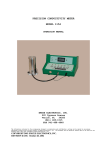
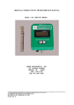
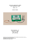
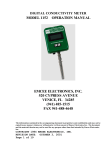
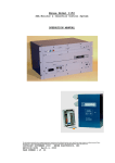
DIGITAL CONDUCTIVITY METER
MODEL 1153 OPERATION MANUAL
EMCEE ELECTRONICS, INC.
520 CYPRESS AVENUE
VENICE, FL 34285
(941) 485-1515
FAX 941-488-4648
The information contained in the accompanying document is proprietary and confidential, and
may not be copied in any manner whatsoever without prior written consent of Emcee
Electronics, Inc. The document and the material therein may not be used for any purpose other
than that intended by Emcee Electronics, Inc.
COPYRIGHT 2005 EMCEE ELECTRONICS, INC.
REVISION DATE: April 14, 2008
Page 1 of 11
DIGITAL CONDUCTIVITY METER
Specifications of the Emcee Model 1153 Digital Conductivity Meter
Continuous Standard Electrical Conductivity Ranges from
0 to 2,000 picosiemens per meter (pS/m)
0 to 20,000 picosiemens per meter (pS/m)
0 to 2,000 picosiemens per centimeter (pS/cm)
0 to 20,000 picosiemens per centimeter (pS/cm)
0 to 100,000 picosiemens per centimeter (pS/cm)
One Pressure Sensitive Switch Operation (Green/White MC Logo)
Red LED Illuminates During Automatic Test Cycle (3 seconds)
Data Stored (Non Volatile) Until Next Test Cycle is Performed
Alphanumeric Liquid Crystal Display (LCD)
Conductivity Measured and Displayed in Whole Numbers
(pS/m or pS/cm)
Optional Embedded Temperature Sensor Available
Text Presentation of Operational Status of Meter is Displayed
Automatic Over Range (OVER) and Low Battery (LOW BAT)
Indications
Powered by Three-Standard (3-volt) Lithium Cylindrical Cells (Generic
Code Panasonic CR 2016)
Fuel and Water Resistant
Approved as being Intrinsically Safe
Listed in American Society of Test and Materials (ASTM)
Standard Test Method D 2624
The information contained in the accompanying document is proprietary and confidential, and
may not be copied in any manner whatsoever without prior written consent of Emcee
Electronics, Inc. The document and the material therein may not be used for any purpose other
than that intended by Emcee Electronics, Inc.
COPYRIGHT 2005 EMCEE ELECTRONICS, INC.
REVISION DATE: January 28, 2008
Page 2 of 11
DIGITAL CONDUCTIVITY METER
TABLE OF CONTENTS
1.0 Scope
Page No.
. . . . . . . . . . . . . . . . 4
2.0 Significance
and Use
. . . . . . . . 4
3.0 Definition . . . . . . . . . . . . . . 4
4.0 Theory of Operation
5.0 Apparatus
. . . . . . . . . 4
. . . . . . . . . . . . . . 5
6.0 Operational Characteristics
7.0 Check Operational Performance
. . . . . 6
. . . . 7
8.0 Test Procedure . . . . . . . . . . . . 8
9.0 Cleaning Procedures
. . . . . . . . . 9
10.0 Battery Replacement . . . . . . . .
10
11.0 Precision . . . . . . . . . . . . .
11
Service & Warranty Policy
See Emcee Electronics, Inc Service and Warranty
Manual
The information contained in the accompanying document is proprietary and confidential, and
may not be copied in any manner whatsoever without prior written consent of Emcee
Electronics, Inc. The document and the material therein may not be used for any purpose other
than that intended by Emcee Electronics, Inc.
COPYRIGHT 2005 EMCEE ELECTRONICS, INC.
REVISION DATE: January 28, 2008
Page 3 of 11
DIGITAL CONDUCTIVITY METER
1. SCOPE
The Emcee Model 1153 Digital Conductivity Meter is a reliable, convenient and
inexpensive instrument for measuring the electrical conductivity of fuels and other
products that have very low electrical conductivities. The unit of measure is
picosiemens per meter (pS/m) commonly referred to as Conductivity Units (CU). The
Meter incorporates all solid-state components and is completely self-contained.
2. SIGNIFICANCE and USE
The ability of a fuel to dissipate charge that has been generated during pumping and
filtering operations is controlled by its electrical conductivity, which depends upon its
content of ion species. If the conductivity is sufficiently high, charges dissipate fast
enough to prevent their accumulation thus decreasing the build up of dangerously
high electrical potentials that could spark and cause a fire and/or explosion. This
problem can be mitigated by increasing the electrical conductivity of the product by
the addition of certain additives. The Emcee Conductivity Meter is typically used to
measure the conductivity before and after the addition of the additives. If it is
necessary to measure conductivities below 1 pS/m, for example in the case of clay
treated fuels or refined hydrocarbon solvents, the Emcee Model 1154 Precision
Conductivity Meter listed in ASTM Test Method D 4308 should be used.
3. DEFINITION
3.1 picosiemens per meter (pS/m), n-the unit of electrical conductivity is also called a
conductivity unit (CU). A siemen is the Standard International (SI) definition of
reciprocal ohm sometimes called mho.
1pS/m = 1 X 10-12 ohms-1 = 1 CU = 1 picomho/m
The Emcee Conductivity Meter displays electrical conductivity in picosiemens/meter
(pS/m) or picosiemens/centimeter (pS/cm).
4. THEORY OF OPERATION
The Emcee Conductivity Meter uses a probe consisting of two concentric stainless
steel electrodes. When the probe is immersed in fuel, and the pressure sensitive
switch is pressed twice, a constant voltage is applied to the electrode s. This results in
an electrical current which is amplified and is shown on the meter display.
The information contained in the accompanying document is proprietary and confidential, and
may not be copied in any manner whatsoever without prior written consent of Emcee
Electronics, Inc. The document and the material therein may not be used for any purpose other
than that intended by Emcee Electronics, Inc.
COPYRIGHT 2005 EMCEE ELECTRONICS, INC.
REVISION DATE: January 28, 2008
Page 4 of 11
DIGITAL CONDUCTIVITY METER
5. APPARATUS
5.1 The Emcee Model 1153 Conductivity Meter complete with probe is shown in Fig.
1.
5.2 The Meter is operated by a single pressure sensitive switch that is covered by and
is directly beneath the Emcee green/white logo as shown in Fig.1. The Switch is used
to retrieve the stored data and to initiate a test.
5.3 The Meter is a portable, hand held device that is battery powered. As shown in
Fig. 2 the batteries can be accessed by removing the top (cap) on the Meter Fig. 1.
5.4 The TOOL shown in Fig. 2 is used as an Allen wrench to remove the 2-screws
that secure the cap to the Meter and to extract the batteries.
Battery Removal Tool
Allen Head
Screw
CAP
Allen Wrench
Batteries
LCD
MC Logo
Pressure
Sensitive
Switch
Red LED
CAP
Figure 1 – Model 1153 Meter
Figure 2 – Batteries, Cap, and Tool
The information contained in the accompanying document is proprietary and confidential, and
may not be copied in any manner whatsoever without prior written consent of Emcee
Electronics, Inc. The document and the material therein may not be used for any purpose other
than that intended by Emcee Electronics, Inc.
COPYRIGHT 2005 EMCEE ELECTRONICS, INC.
REVISION DATE: January 28, 2008
Page 5 of 11
DIGITAL CONDUCTIVITY METER
Male Banana Plug
5.5 The probe Inserted in the sample that is
being
tested with the ground lead attached to the Meter
and
to the sample container is shown in Fig. 3. The
location of the female banana plug on the Meter
Ground Lead
and
the Allen screw is also shown in Fig. 4.
Female Banana
Jack
Allen Screw
Alligator Clip
Stainless
Steel Beaker
Figure 3 – Test Set Up
Figure 4 – Female Banana
Jack and Allen Screw
6. OPERATIONAL CHARACTERISTICS
6.1 To view the previous measurement that is stored in memory, depress the pressure
sensitive switch (MC Logo) once. Both the conductivity (pS/m) and the temperature
(C and F) will be displayed and retained until another test is performed.
6.2 To initiate a test, depress the pressure sensitive switch (MC Logo) once and then
again when EMCEE is displayed. The test will measure conductivity and the
temperature of the sample and store the results in memory.
The information contained in the accompanying document is proprietary and confidential, and
may not be copied in any manner whatsoever without prior written consent of Emcee
Electronics, Inc. The document and the material therein may not be used for any purpose other
than that intended by Emcee Electronics, Inc.
COPYRIGHT 2005 EMCEE ELECTRONICS, INC.
REVISION DATE: January 28, 2008
Page 6 of 11
DIGITAL CONDUCTIVITY METER
7. CHECK OPERATIONAL PERFORMANCE
7.1 Zero Check
7.1.1 With the probe out of the sample to be tested, depress the pressure sensitive
switch once and then again when EMCEE is displayed.
7.1.2 The display will scroll through the test operation and the new conductivity data
should read “0”. The temperature of the environment will be displayed.
7.1.3 If a number other than “0” is displayed, this probably is an indication that the
probe is contaminated and should be cleaned. (See Paragraph 9. Cleaning
Procedures)
7.2 Over-Range Check – Conductivity is greater than 2K pS/m
7.2.1 Insert the probe into a sample of alcohol (isopropano l), depress the pressure
sensitive switch once and then again when EMCEE is displayed.
7.2.2 At the end of the test period when the LED extinguishes, the display will scroll
through and in lieu of displaying a numerical value for the conductivity the display
will read “OVER” thus indicating that the measurement is over range and the meter is
operating properly.
Outer Conductor
Inner Conductor
Figure 5 – Inner and Outer Conductors
The information contained in the accompanying document is proprietary and confidential, and
may not be copied in any manner whatsoever without prior written consent of Emcee
Electronics, Inc. The document and the material therein may not be used for any purpose other
than that intended by Emcee Electronics, Inc.
COPYRIGHT 2005 EMCEE ELECTRONICS, INC.
REVISION DATE: January 28, 2008
Page 7 of 11
DIGITAL CONDUCTIVITY METER
8.0 TEST PROCEDURE
CAUTION: This device must be grounded before and after introduction of the probe
into the tank and remain grounded until after complete withdrawal from the tank.
8.1 To initiate a test. depress the pressure sensitive switch once and then again when
EMCEE is displayed. The following will occur:
8.1.1 The red LED located just above the pressure sensitive switch (MC Logo) will
begin to blink indicating that the meter is in the ready mode to perform a test.
8.2 Insert the probe into the sample up to and covering the four holes in the probe.
8.2.1 “READ NEW DATA” will be displayed.
8.2.2 The red LED will stop blinking and remain on indicating that a test is in
progress. Hold the meter steady during the test period.
8.2.3 A broken line (----------) will blink on and off three times (3-seconds) during
the test period.
8.2.4 At the end of the test period, the red LED will extinguish indicating that the test
is complete and the measurements are stored in memory.
8.2.5 “NEW DATA PS/M” will be displayed
8.2.5.1 Value of measurement will be displayed – Example 325
8.2.5.2 The temperature of the sample will be displayed as follows:
8.2.5.2.1 Temperature in Degrees Centigrade - Example: 28.8C
8.2.5.2.2 Temperature in Degrees Fahrenheit - Example: 83.8F
Note: The new data (pS/m and temperature) will replace the previous data and will
be stored in memory until another test is performed.
It is recommended that the probe be rinsed with alcohol followed by toluene prior to
performing another test or storing the meter.
The information contained in the accompanying document is proprietary and confidential, and
may not be copied in any manner whatsoever without prior written consent of Emcee
Electronics, Inc. The document and the material therein may not be used for any purpose other
than that intended by Emcee Electronics, Inc.
COPYRIGHT 2005 EMCEE ELECTRONICS, INC.
REVISION DATE: January 28, 2008
Page 8 of 11
DIGITAL CONDUCTIVITY METER
9. CLEANING PROCEDURES
9.1 In normal use, the probe should be cleaned with toluene or a mixture of heptane
and isopropanol and air-dried after use, to ensure that ionic materials absorbed on the
probe during previous tests will not contaminate the sample and give an erroneous
result. The probe can be disassembled by rotating the outer conductor
counterclockwise. Typically, the probe is cleaned by rinsing it using alcohol
followed by a toluene (or with some of the sample to be tested). Fig. 6 Shows the
Probe disassembled.
9.2 If the cell is in contact with water and the
instrument is switched on, an immediate off scale
reading will be obtained. If the cell has been in
contact with water, it shall be thoroughly rinsed with
cleaning solvent, preferably isopropyl alcohol, and
dried with a stream of air.
9.3 The meter may display a non-zero reading caused
by condensation forming on the cell when the meter
is taken from a cool, dry environment and subjected
to hot, humid conditions. This condition can be
avoided by storing the cell at a temperature 2 to 5°C
in excess of the ambient temperature, when
practicable
Figure 6 – Probe Disassembled
10. BATTERY REPLACEMENT
10.1 The Model 1153 meter has an internal battery check circuit. If the batteries are
weak, the meter will turn on ‘LOW BAT” will be displayed and the meter will turn
off and not allow a measurement to be performed. If the batteries are too weak, the
meter will not turn on.
The information contained in the accompanying document is proprietary and confidential, and
may not be copied in any manner whatsoever without prior written consent of Emcee
Electronics, Inc. The document and the material therein may not be used for any purpose other
than that intended by Emcee Electronics, Inc.
COPYRIGHT 2005 EMCEE ELECTRONICS, INC.
REVISION DATE: January 28, 2008
Page 9 of 11
DIGITAL CONDUCTIVITY METER
Note: The stored data will not be affected even if the batteries are replaced.
WARNING! To prevent ignition of flammable or combustible atmospheres,
disconnect power before servicing.
WARNING! To reduce the risk of ignition of a flammable or explosive atmosphere,
batteries must be changed only in a location known to be non-hazardous. Do not mix
new batteries with used batteries, or mix batteries from different manufactures.
Battery requirements: 3 - batteries Panasonic type CR 2016
10.2 When battery replacement is required, using the TOOL (See Fig. 2), remove the
two screws (Allen head) that secure the top (cap) of the meter to the body. The
screws are located on the lateral sides of the meter cap. (See Figs. 1 and 4)
10.2.1 Remove the cap. Some degree of force will be required to overcome the drag
caused by the “O” ring.
10.2.2 The batteries (3) are located behind the printed circuit boards adjacent to the
back of the meter. Fig. 2 Shows the location of the batteries in the meter.
10.2.3 Remove the batteries using the TOOL (See Fig. 2) that was furnished with the
meter.
10.2.4 Insert the new batteries (the TOOL is not required). Assure that the polarity of
the batteries is correct (positive faces to the back of the meter which is the side
opposite of the display). See Fig. 2 for battery location in meter.
10.2.5 Replace the cap and secure it using the 2-screws.
10.2.6 Check by depressing the pressure sensitive switch once to assure that the
batteries corrected the problem. If the display does not illuminate, this may be an
indication that the meter requires factory repair.
11. PRECISION*
The electrical parameters of the meter are factory calibrated to 1% of reading.
However, due to variations in product measurement characteristics, the repeatability
(r) and reproducibility (R) are as follows:
PS/M
r
R
The information contained in the accompanying document is proprietary and confidential, and
may not be copied in any manner whatsoever without prior written consent of Emcee
Electronics, Inc. The document and the material therein may not be used for any purpose other
than that intended by Emcee Electronics, Inc.
COPYRIGHT 2005 EMCEE ELECTRONICS, INC.
REVISION DATE: January 28, 2008
Page 10 of 11
DIGITAL CONDUCTIVITY METER
1
1
1
15
6
8
20
7
9
30
9
11
50
13
16
70
15
19
100
19
24
200
29
36
300
37
46
500
51
62
700
62
76
1000
77
94
1500
98
120
PS/M – picosiemens per meter
r = Repeatability - Maximum allowable difference between 2-successive
measurements performed by the same operator using the same meter to test the same
sample.
R = Reproducibility – Maximum allowable difference between 2-measurements
performed on the same sample by 2different operators using 2-different meters.
*Precision is based on a Inter-laboratory Test (ILT) Program conducted in November
2004 under the auspices of the American Society of Test and Materials (ASTM)
Internationa l. Since the Program was conducted at room temperature (23ºC – 73.4ºF)
the precision may vary at other temperatures.
The information contained in the accompanying document is proprietary and confidential, and
may not be copied in any manner whatsoever without prior written consent of Emcee
Electronics, Inc. The document and the material therein may not be used for any purpose other
than that intended by Emcee Electronics, Inc.
COPYRIGHT 2005 EMCEE ELECTRONICS, INC.
REVISION DATE: January 28, 2008
Page 11 of 11