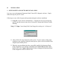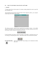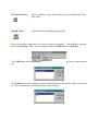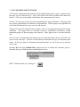
1
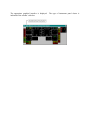
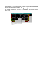
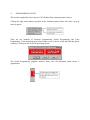
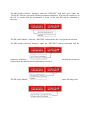
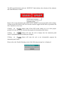
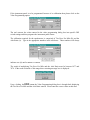
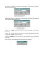
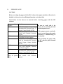
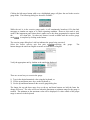
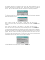
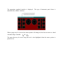
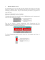
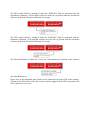
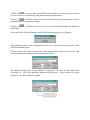
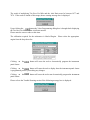
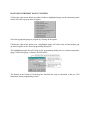
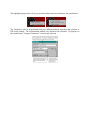
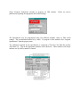
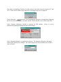
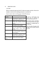
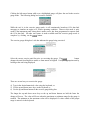
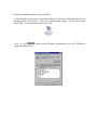
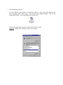
INTERNATIONAL
INSTRUMENT P ANEL C LUSTER
Software
®
User’s Manual
International Truck and Engine Corporation®
Copyright
Please read through the License agreement accompanying the software.
The International Instrument Panel Cluster (IPC) software is written for International Truck and
Engine Corporation and is protected by United States copyright laws and international treaty
provisions. Therefore, you must treat the SOFTWARE like any other copyrighted material. You
may, however, either (a) make one copy of the SOFTWARE solely for backup or archival
purposes, or (b) transfer the SOFTWARE to a single hard disk, provided you keep the original
solely for backup or archival purposes. You cannot copy the written materials accompanying the
SOFTWARE.
This manual is written for International Truck and Engine Corporation by SU Enterprise, Inc.
and is protected by United States copyright laws and international treaty provision.
Third-party brands and names are the property of their respective owners.
The authors assume no responsibility for any errors or omissions which may appear in this
document nor do they make any commitment to update the information contained herein.
Copyright 1999, 2000, 2001, Rev. 2.0
TABLE OF CONTENTS
I. INTRODUCTION
1. Software Overview
I.1.1
2. System Requirements
I.2.1
3. Nomenclature
I.3.1
II. INSTALLATION
1. System Setup and Software Installation
II.1.1
III. HOW TO USE I NSTRUMENT PANEL CLUSTER SOFTWARE
1. Basics
III.1.1
2. IPC for Medium Duty Trucks
III.2.1
A. Programming Gauge
B. Exercise Gauge
3. IPC for Heavy Duty Trucks
III.3.1
A. Programming Gauge
B. Exercise Gauge
4. System and Software Trouble Shooting
III.4.1
I. INTRODUCTION
1. SOFTWARE OVERVIEW
The International electronic instrument panel clusters consists of four basic types: Pre-1997
medium-duty, Post-1997 medium-duty, Pre-1994 heavy-duty, and Post-1994 heavy-duty. To
properly diagnosis and program these clusters please follow the instructions outlined in this and
other International manuals. The International Panel Cluster software provides the capabilities to
1)
Attempt to automatically distinguish the type of instrument panel cluster.
2)
Program specific truck application settings.
3)
Exercise data link driven gauges.
2. SYSTEM REQUIREMENTS
The International Instrument Panel Cluster diagnostic software is designed and developed to
provide diagnosis to the International Instrument Panel Cluster for both Heavy-duty truck and
Medium duty truck.
System requirements are as follow:
1)
PC with Pentium® or Pentium® equivalent or replacement CPU.
32MB of system RAM.
10MB of free system HD.
CD-ROM drive and/or 3½” Floppy drive.
2)
Microsoft Windows® Operating System. Depends on the version of the International Instrument Panel Cluster
software.
3)
International Instrument Panel Cluster diagnostic software (on CD or 3½” Floppies)
4)
International approved EZ-Tech Interface cable.
3. NOMENCLATURE
The following are the nomenclatures used within this manual. Please read this section carefully
and understand the meaning of the actions required.
Click or Clicking
For EZ-Tech users this indicates tapping on the lower left-hand area of the
touch pad once. For PC users this indicates tapping on the left mouse
button.
Double click or
Double clicking
For EZ -Tech users this indicates tapping on the
lower left -hand area of the touch pad twice in succession. For PC users this indicates
tapping on the left mouse button twice in succession.
Right Click
For EZ -Tech users this indicates tapping on the upper left-hand area of the touch pad
once. For PC users this indicates tapping on the right mouse button.
Click and drag
For EZ -Tech users this indicates tapping on the lower left -hand area of the touch pad
marked by a lock symbol and then using the main area of the touch pad to move the
mouse pointer.
Hit
Indicates depressing and then releasing a key on the keyboard.
ALT
Indicates the action whereby the “Alt” key on the keyboard is depressed while another
key on the keyboard is hit.
Scroll bar
The horizontal-scroll bar
is normally at the bottom
of the window. Click on the left arrow button to scroll left. Click on the
right arrow button to scroll right. Click on the area to the left of the slider
to page left. Click on the area to the right of the slider to page right. Or
simply use the slider by clicking and dragging.
The vertical-scroll bar is normally at the right of the window. Click
on the up arrow button to scroll up. Click on the down arrow button
to scroll down. Click on the area to the top of the slider to page up.
Click on the area to the bottom of the slider to page down. Or simply
use the slider by clicking and dragging.
II.
INSTALLATION
1. SYSTEM SETUP AND SOFTWARE INSTALLATION
It is easy to set up International Instrument Panel Cluster (IPC) diagnostic software. Simply
follow the steps on your PC screen.
Following are some of the frequent asked questions during the software installation.
1) Using CD. Insert CD into CD-ROM drive. If Windows® does not automatically
start to setup the software, then refer to Section III-4 System and Software Trouble
Shooting.
Using 3 ½” floppy. Insert Setup Disk#1 into floppy drive and type in “A:\Setup.exe”.
2) Always follow the setup instruction on the screen. If you are unsure of the proper
responses to any questions during the install process, please select the default values
assigned by the install process.
3) When the setup installation has been successfully installed, the Instrument Panel
Cluster diagnostics icon should be embedded in the VEHICLE D IAGNOSTIC folder.
Double click on the VEHICLE DIAGNOSTIC Folder to bring up the Instrument Panel
Cluster diagnostics software shortcut icon.
III.
HOW TO USE THE IPC DIAGNOSTIC SOFTWARE
1. BASICS
To begin using this tool, please spend a few minutes reading through this section to gain the
basics behind the tool.
After launching the International Instrument Panel Cluster diagnostic software, your computer
should display the following main window.
The software provides a menu bar that is right below the window’s title bar. All available
features of the software can be accessed via the menu bar. The primary interface for the use of
the software is based on the type of instrument panel cluster.
For the frequently used actions, a tool bar is provided. The toolbar is a quick and easy way to
select the type of instrument panel cluster. Each toolbar button will be described briefly below.
IPC è Medium Duty
Opens Instrument Panel Cluster dialog box for International medium
duty trucks.
IPC è Heavy Duty
Opens Instrument Panel Cluster dialog box for International Heavy
Duty trucks.
Help è About
Opens the software help about message box.
Prior to starting the configuration, the software must be set properly. Click on File in the menu
bar and then Settings. There are two settings available: COM Device, and COM Port.
The COM Device selection configures which interface cable is connected to the communication
port.
The COM Port selection configures which communication port the interface cable is connected
to. This is determined by looking at the back of the computer.
2. IPC FOR MEDIUM DUTY TRUCKS
All electronic instrument panel clusters built for Medium Duty trucks can be categorized into
two types: pre-1997 and post-1997. Series 1000, 2000, 3000, 4000, and 8000 trucks built since
March 1, 1992, have been installed with Medium Duty instrument panel clusters.
The pre-1997 types may require electronic programming for proper calibration. The gauges that
may require programming are tachometer and speedometer. If these gauges are programmed to
use the data link, then they may be exercised with this tool.
The post-1997 types have data link driven gauges. There is no programming required for proper
calibration. The gauges that are data link driven are speedometer, tachometer, coolant
temperature gauge, oil pressure gauge, and voltmeter. These gauges may be exercised with this
tool.
The exact type of instrument panel cluster must be determined before the tool will allow the
correct access and usage. The tool will first attempt to determine the type of instrument panel
cluster. If the type cannot be determined automatically then it is left to the user to select the
correct type.
Selecting IPC and then Medium Duty prompts the tool to initiate the automatic query to
determine the type of Medium Duty instrument panel cluster.
HINT: Toolbar shortcut is by clicking on
The following message box is displayed requesting to verify that the truck under service can be
accessed using this tool.
This tool cannot be used to service trucks with International 3 Box electronic engines or NGD
engines built prior to November 1, 1997. Please refer to the service manuals on instruction as to
how to properly service these instrument panel clusters. If you are servicing one of these trucks
please click on the button.
However, if the truck that you
used and you should click on
are servicing is not one of these, then this tool may be
the button.
At this time the tool will automatically request for information from the instrument panel cluster.
If the tool is able to determine the type of instrument panel cluster then the appropriate message
box is displayed indicating the type of instrument panel cluster that is under service.
The following message box is displayed if the service tool cannot determine the type of
instrument panel cluster via the automatic request. Please turn the ignition key on and off and
back on. This causes the instrument panel cluster to broadcast its own identity information.
The following message box is displayed if the identity information of the electronic instrument
panel cluster cannot be received.
If the vehic le was built prior to November 1, 1997, please click on the
button.
This will cause the pre-1997 Medium Duty instrument panel cluster interface to become
available.
If the vehicle was built on or after November 1, 1997, please click on the
button.
This will cause the post-1997 Medium Duty instrument panel cluster to become available.
A general message indicating the type instrument panel cluster is displayed prior to displaying
the graphical user interface. Please confirm that the physical DIP switches are all set to the zero
position. This tool is unable to electronically program the instrument panel cluster if any of the
DIP switches is not set at the zero position. Also, this tool may not be able to exercise the gauge
depending on which of the DIP switches are not set to the zero position.
Acknowledging the above message box by clicking on the
button.
The appropriate graphical interface is displayed.
indicated in the window’s title bar.
The type of instrument panel cluster is
When a gauge may be exercised or programmed, the mouse pointer will change its form from an
arrow to a hand with index finger extended.
è
The gauge that may be accessed using this tool is also highlighted when the mouse pointer is
placed over it.
A.
PROGRAMMING GAUGE
This section is applicable only to the pre-1997 Medium Duty instrument panel clusters.
Clicking the right mouse button anywhere on the instrument panel cluster will cause a pop up
menu to appear.
There are two methods of electronic programming: Switch Programming and Value
Programming. If the instrument panel cluster under service is driven via the data link then please
confirm by clicking on the Switch Programming option.
The Switch Programming graphical interface shows how the instrument panel cluster is
programmed.
The DIP switches labeled 1 through 8 under the “SWITCH1” bank and 1 and 2 under the
“SWITCH2” bank are associated with the speedometer calibration. If all ten DIP switches are in
the ON (1) position then the speedometer is driven via the data link and no calibration is
necessary.
The DIP switch labeled 3 under the “SWITCH2” bank indicates the Two-Speed axle selection.
The DIP switches labeled 4 through 6 under the “SWITCH2” bank are associated with the
tachometer calibration. If all three DIP switches are in the ON (1) position then the tachometer
is driven from the data link and no calibration is necessary.
The DIP switch labeled 7 under the “SWITCH2” bank indicates the tachometer full range scale.
The DIP switch labeled 8 under the “SWITCH2” bank indicates the selection of the odometer
unit either Kilometer or Miles.
Please refer to the instrument panel cluster service manual for the proper DIP switch settings.
Clicking on the DIP switch it self will cause the switch to toggle from the OFF (0) position to the
ON (1) position or vise versa.
Clicking on the
button when all the DIP switch settings are set to their proper
position will cause the tool to electronically program the instrument panel cluster.
Clicking on the
button will cause the tool to display how the instrument panel
cluster is programmed prior to making any changes.
Clicking on the
instrument panel cluster.
button will cause the tool to not electronically program the
Please refer to the Trouble Shooting section if the following message box is displayed:
If the instrument panel is to be programmed because of re-calibration then please click on the
Value Programming option.
The tool converts the values entered in the value programming dialog box into specific DIP
switch settings and then programs the instrument panel cluster.
The calibration required for the speedometer is comprised of Tire Revs Per Mile (R) and the
Axle Ratio (A). Type in the appropriate numbers in the edit boxes. These numbers will always
indicate zero (0) until a number is entered.
The result of multiplying Tire Revs Per Mile and the Axle Ratio must be between 1077 and
7676. If the result is outside of this range then a warning message box is displayed.
Upon clicking the
button the Value Programming dialog box is brought back displaying
the Tire Revs Per Mile and the Axle Ratio entered. Please enter the correct values at this time.
The calibration required for the tachometer is labeled Engine. Please select the appropriate
engine from the drop down list.
Make the other selections as appropriate by clicking the proper selections for Two-Speed Axle
Ratio, Tachometer Range, and Conversion.
Clicking on
panel cluster.
the
button will cause the tool to electronically program the instrument
Clicking on the
button will cause the tool to display how the instrument panel cluster
is programmed prior to you making any cha nges.
Clicking on the
panel cluster.
button will cause the tool to not electronically program the instrument
Please refer to the Trouble Shooting section if this message box is displayed:
B.
EXERCISE GAUGE
CAUTION
Before exercising the gauges with the IPC software the engine controller will need to be
disabled so it doesn't send conflicting information on the data link.
Listed below are the fuses to be removed before exercising gauges with the IPC
software.
Fuse
Number
F-5
Circuit Model
2000, 4000, 8000 models with the
International® Diamond Logic ™
Engine Control Module (ECM).
F-17
2000, 4000, 8000 models with the
Detroit and Cummins electronic
engines.
F-11
2000, 4000, 8000 models with the
Caterpillar electronic engines.
C1
3600, 3800 and 4000FBC models
with the International® Diamond
Logic Engine Control Module
(ECM).
F6-D
Conventional Heavy Duty (not cab
over) with Caterpillar, Cummins
and Detroit engines.
F10-C
Conventional Heavy duty with the
International® Diamond Logic™
Engine Control Module (ECM).
F2-C
Conventional Heavy Duty cab
(Fuse for ignition over models with electronic
relay)
engines.
Be sure to verify this is the
correct fuse by checking the label
on the fuse panel cover.
If the gauges operate erratically,
there is a good chance the engine
controller is communicating on
the data link.
After exercising the gauges with
the IPC software, please reinstall
the fuses.
Clicking the left mouse button while over a highlighted gauge will place the tool in the exercise
gauge mode. The following dialog box becomes available:
While the tool is in the exercise gauge mode, it will continuously broadcast ATA data link
messages to simulate an engine or a vehicle operating condition. However, this mode is only
useful if the instrume nt panel cluster that is under service has been programmed to operate from
the
ATA data link. No other tool feature is made available until the exercise gauge
mode
is complete by clicking on the button.
The exercise gauge dialog box’s title bar indicates the gauge being exercised.
Select the correct exercise unit first prior to
exercising the
button changes the unit from English to metric or from metric to English.
gauge.
The
Verify the appropriate unit by looking at the unit being displayed.
There are several ways to exercise the gauge:
1) Type in the desired numerical value using the keyboard, or
2) Use the up and down arrow keys on the keyboard, or
3) Use the up and down buttons in the exercise gauge dialog box.
The longer the up and down arrow keys or the up and down buttons are held the faster the
change will occur. The value will freeze when the maximum or minimum range for the gauge is
reached. The minimum or the maximum value will be displayed if a value outside of the proper
range is entered via the keyboard.
3. IPC FOR HEAVY DUTY TRUCKS
All electronic instrument panel clusters built for heavy-duty trucks can be categorized into two
types: pre-1994 and post-1994. Series 5000, 9200, 9300, 9400, 9600, 9700, and 9800 trucks
built since January 1, 1994, have been installed with the heavy-duty instrument panel cluster,
also known as the command center.
The pre-1994 types may require electronic programming for proper calibration. The gauges that
may require programming are tachometer and speedometer. If these gauges are programmed to
use the data link, then they may be exercised with this tool.
The post-1994 types may require electronic programming for proper calibration. The gauges that
may require programming are tachometer, speedometer, coolant temperature gauge, oil pressure
gauge, voltmeter, fuel gauge, and odometer. The gauges that may be exercised by this tool are
speedometer, tachometer, coolant temperature gauge, oil pressure gauge, and voltmeter. This
tool will only exercise the gauges that are programmed to use the data link.
The exact type of instrument panel cluster must be determined before the tool will allow the
correct access and usage. The tool will first attempt to determine the type of instrument panel
cluster. If the type can not be determined automatically, then it is left to the user to select the
correct type.
Selecting IPC and then Heavy Duty prompts the tool to initiate the automatic query to
determine the type of heavy-duty instrument panel cluster.
HINT: Toolbar shortcut is by clicking on
At this time, the tool will automatically request for information from the instrument panel
cluster. If the tool is able to determine the type of instrument panel cluster, then the appropriate
message box is displayed indicating the type of instrument panel cluster that is under service.
The following message box is displayed if the service tool cannot determine the type of
instrument panel cluster via the automatic request. Please turn the ignitio n key on and off and
back on. This causes the instrument panel cluster to broadcast its own identity information.
The following message box is displayed if the identity information of the electronic instrument
panel cluster cannot be received.
If the vehicle was built prior to January 1, 1994, please click on the
button. This will cause the pre-1994 Heavy Duty instrument panel cluster interface to become
available.
If the vehicle was built on or after January 1, 1994, please click on the
button. This will cause the post-1994 Heavy Duty instrument panel cluster to become available.
A general message indicating the type instrument panel cluster is displayed prior to displaying
the graphical user interface. Please confirm that the physical DIP switches are all set to the zero
position. This tool is unable to electronically program the instrument panel cluster if any of the
DIP switches is not set at the zero position. Also this tool may not be able to exercise the gauge
depending on which of the DIP switches is not set to the zero position.
Acknowledging the above message box by clicking the
button.
The appropriate graphical interface is displayed.
indicated in the window’s title bar.
The type of instrument panel cluster is
When a gauge may be exercised, the mouse pointer will change its form from an arrow to a hand
with index finger extended.
¢
The gauge that may be access using this tool is also highlighted when the mouse pointer is
placed over it.
A.
PROGRAMMING GAUGE
The programming for the pre-1994 and post-1994 instrument panel clusters for heavy-duty
trucks are very different. The pre-1994 instrument panel clusters are programmed via a similar
methodology as the DIP switches. The post-1994 instrument panel clusters are programmed via
actual values only.
PRE-1994 INSTRUMENT PANEL CLUSTERS
Clicking the right mouse button anywhere besides a highlighted gauge on the instrument panel
cluster will cause a pop up menu to appear.
There are two methods of electronic programming: Switch Programming and Value
Programming. If the instrument panel cluster under service is driven via the data link then please
confirm by clicking on the Switch Programming option.
The Switch Programming graphical interface shows how the instrument panel cluster is
programmed.
The DIP switches labeled 1 through 10 under the “SWITCH1” bank are associated with the
speedometer calibration. If all ten DIP switches are in the ON (1) position, then the speedometer
is driven via the data link and no calibration is necessary.
The DIP switches labeled 1 though 8 under the “SWITCH2” bank are associated with the
tachometer calibration. If all eight DIP switches are in the ON (1) position, then the tachometer
is driven via the data link and no calibration is necessary.
The DIP switch labeled 10 under the “SWITCH2” bank indicates the selection of the odometer
unit either Kilometer or Miles.
Please refer to the instrument panel cluster service manual for the proper DIP switch settings.
Clicking on the DIP switch it self will cause the switch to toggle from the OFF (0) position to the
ON (1) position or vise versa.
Clicking on
the button when all the DIP switch settings are set to their proper position
will cause the tool to electronically program the instrument panel cluster.
Clicking on
the button will cause the tool to display how the instrument panel cluster is
programmed prior to making any changes.
Clicking on
panel cluster.
the button will cause the tool to not electronically program the instrument
Please refer to the Trouble Shooting section if the following message box is displayed.
If the instrument panel is to be programmed because of re-calibration, then please click on the
Value Programming option.
The tool converts the values entered in the value programming dialog box into specific DIP
switch settings and then programs the instrument panel cluster.
The calibration required for the speedometer is comprised of Tire Revs Per Mile (R) and the
Axle Ratio (A). Type in the appropriate numbers in the edit boxes. These numbers will always
indicate zero (0) until a number is entered.
The result of multiplying Tire Revs Per Mile and the Axle Ratio must be between 1077 and
7676. If the result is outside of this range, then a warning message box is displayed.
Upon clicking the
button the Value Programming dialog box is brought back displaying
the Tire Revs Per Mile and the Axle Ratio entered.
Please enter the correct values at this time.
The calibration required for the tachometer is labeled Engine. Please select the appropriate
engine from the drop down list.
Clicking on
panel cluster.
the
button will cause the tool to electronically program the instrument
Clicking on the
button will cause the tool to display how the instrument panel cluster
is programmed prior to you making any changes.
Clicking on
panel cluster.
the
button will cause the tool to not electronically program the instrument
Please refer to the Trouble Shooting section if the following message box is displayed.
POST-1994 INSTRUMENT PANEL CLUSTERS
Clicking the right mouse button anywhere besides a highlighted gauge on the instrument panel
cluster will cause a pop up menu to appear.
Select the appropriate gauge to program by clicking on the option.
Clicking the right mouse button over a highlighted gauge will either cause an intermediate pop
up menu to appear or the desired programming dialog box.
The highlighted gauges that will bring up the programming dialog box are coolant temperature
gauge, oil pressure gauge, voltmeter, and fuel meter.
The buttons at the bottom of the dialog box functions the same as described in the pre-1994
instrument cluster programming section.
The highlighted gauges that will pop up an intermediate menu are tachometer and speedometer.
The Tachometer may be programmed using two different methods: dropdown list selection or
DIP switch settings. The recommended method is by dropdown list selections. To program via
this method select “Program Tachometer” from the pop up menu.
Select “Program Tachometer (switch)” to program via DIP switches.
publications regarding the appropriate DIP switch settings.
Please see service
The Speedometer may be programmed using two different methods: values or DIP switch
settings. The recommended method is by values. To program via this method select “Program
Speedometer” from the pop up menu.
The calibration required for the speedometer is comprised of Tire Revs Per Mile (R) and the
Axle Ratio (A). Type in the appropriate numbers in the edit boxes. These numbers will always
indicate zero (0) until a number is entered.
The result of multiplying Tire Revs Per Mile and the Axle Ratio must be between 1077 and
7676. If the result is outside of this range then a warning message box is displayed.
Upon clicking the
button the Value Programming dialog box is brought back displaying
the Tire Revs Per Mile and the Axle Ratio entered. Please enter the correct values at this time.
Select “Program Tachometer (switch)” to program via DIP switches.
publications regarding the appropriate DIP switch settings.
Please see service
Select “Program Odometer” to program the odometer. The Odometer dialog box will appear
allowing the odometer to be changed. The value displayed will always indicate zero (0) until a
value is entered.
B.
EXERCISE GAUGE
CAUTION
Before exercising the gauges with the IPC software the engine controller will need to be
disabled so it doesn't send conflicting information on the data link.
Fuses to remove before exercising gauges with the IPC software.
Fuse
Circuit Model
Number
F-5
2000, 4000, 8000 models with the
International® Diamond Logic™
Engine Control Module (ECM).
F-17
2000, 4000, 8000 models with the
Detroit and Cummins electronic
engines.
F-11
2000, 4000, 8000 models with the
Caterpillar electronic engines.
C1
3600, 3800 and 4000FBC models
with the International® Diamond
Logic™ Engine Control Module
(ECM).
F6-D
Conventional Heavy Duty (not cab
over) with Caterpillar, Cummins and
Detroit engines.
F10-C
Conventional Heavy duty with the
International® Diamond Logic™
Engine Control Module (ECM).
F2-C
Conventional Heavy Duty cab over
(Fuse for ignition models with electronic engines.
relay)
Be sure to verify this is the
correct fuse by checking the
label on the fuse panel cover.
If the gauges operate erratically,
there is a good chance the engine
controller is communicating on
the data link.
After exercising the gauges with
the IPC software, please reinstall
the fuses.
Clicking the left mouse button while over a highlighted gauge will place the tool in the exercise
gauge mode. The following dialog box becomes available.
While the tool is in the exercise gauge mode, it will continuously broadcast ATA data link
messages to simulate an engine or a vehicle operating condition. However this mode is only
useful if the instrument panel cluster that is under service has been programmed to operate from
the ATA data link. No other tool feature is made available until the exercise gauge mode is
complete by clicking on the
button.
The exercise gauge dialog box’s title bar indicates the gauge being exercised.
Select the correct exercise unit first prior to exercising the gauge. The
button
changes the unit from English to metric or from metric to English. Verify the appropriate unit by
looking at the unit being displayed.
There are several ways to exercise the gauge:
4) Type in the desired numerical value using the keyboard, or
5) Use the up and down arrow keys on the keyboard, or
6) Use the up and down buttons in the exercise gauge dialog box.
The longer the up and down arrow keys or the up and down buttons are held the faster the
change will occur. The value will freeze when the maximum or minimum range for the gauge is
reached. The minimum or the maximum value will be displayed if a value outside of the proper
range is entered via the keyboard.
4. SYSTEM AND SOFTWARE TROUBLE SHOOTING
1. If you have lost the sessions that were provided by the install disks and you do not have the
install disks any more, please use Windows copy function to retrieve the lost file. The back
up copy of the session files is located in the Factory folder.
2. If the communication link has failed, please follow the steps outlined below.
Note:The following steps are recommended only for PC to Navistar Truck Interface cable,
Navistar EZ-Tech Interface cable, or International EZ- Tech Interface cable.
1)
The interface cable must be connected prior to executing the Instrument Panel Cluster
software. Exit the software, connect the cable, run the software again. Make certain that
the correct communication port is selected in the software please go to step 2 if still
unable to communicate on the ATA data link.
2)
Disconnect and reconnect the interface cable from the truck’s diagnostic connector
(Deutsch connector). Make sure the interface cable is secure on both the truck’s
diagnostic connector and the PC communication (COM) port. Attempt to run the
software again. Please go to step 3 if still unable to communicate on the ATA data link.
3)
If the “Power ON/OFF” indicator is not lit, the truck battery may be low or the truck
wiring harness may be faulty. For 6 pin Deutsch connector, check voltage between pin C
(VBAT) and pin E (GND) on the truck’s diagnostic connector. For 9-pin Deutsch
connector, check voltage between pin B (VBAT) and pin A (GND) on the truck’s
diagnostic connector. If the voltage is 9V DC or greater, please replace the interface
cable.
If the “Power ON/OFF” indicator is lit, then go to step 4 if “ATA” (for Navistar EZ-Tech
Interface cable or International EZ-Tech cable) or “RXD” (for PC to Navistar Truck
Interface cable) indicator is flashing red; if neither indicators on the interface cable are
flashing, then go to step 5.
4)
Try connecting to another PC communication port and/or use another serial cable.
Change the settings in the software to open the new selected communication port.
Replace the interface cable if still unable to communicate on the ATA data link.
5)
Check if the key switch is turned on. Replace the interface cable if key switch was
turned on.
3. Software installation problem using CD-ROM
Use the Windows control panel to install the software. Click on the Start button in the lower
left- hand corner of the screen. Click on the option labeled Settings. Click on the Control
Panel folder. Locate and double click on the icon
Click on the
button to have Windows automatically locate the CD-ROM to
initiate the install process.
4. To Un-Install the software
Use the Windows control panel to un- install the software. Click on the Start button in the
lower left- hand corner of the screen. Click on the option labeled Settings. Click on the
Control Panel folder. Locate and double click on the icon
Click on the application to be removed in the list and click on the
button to have Windows remove the software.