1
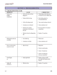
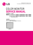
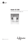
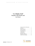
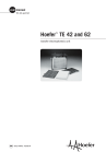
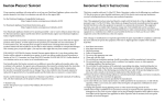
Operator Instruction
and
Safety regulations
Induction Heating system
JO960 A
T 65 1 0505
User and Service manual JO960
Ver. 2.0
Introduction
The Operator Instructions must be read by all personnel handling or
repairing the equipment. By following this manual the operator should be
able to undertake correct and safe operation of the equipment.
The Technical Service Information should be read through by the
operator as well as service personnel. However only qualified personnel
should carry out troubleshooting and maintenance.
Safety instructions
Safety instructions will be found throughout the manual where
appropriate. All safety instructions will be marked with the following
symbol:
Advice and warnings
Important information is marked with the symbol below. This information
might be of greatest importance to avoid operation disturbances or to
avoid injury to persons.
Ver. 1.1
1
User and Service manual JO960
Ver. 2.0
General information
J0960 A is a mobile induction generator with a built in cooling system.
The JO960 has been designed for heating all normally magnetic
material. The JO960 will concentrate a powerful magnetic field at the end
of the heating tip. This magnetic field creates eddy currents in the
material, thus creating heat.
Technical data
Size: (including handles and wheels)
1300 x 660 x 900 mm (LxWxH)
Weight: (full water tank)
180 Kg
Output power:
13 kW
Frequency:
15 kHz
Enclosure:
IP62
Installation / Mains supply
Mains supply:
3 x 380-400V 3Ph+PE
Frequency:
50/60 Hz
Recommended fuse:
32 A
Ver. 1.1
2
User and Service manual JO960
Ver. 2.0
Safety precautions and hazards
General
All those operating, maintaining or working in close proximity to the
equipment must read and understand the safety instructions in this
manual.
• Due to very high voltages the casing must not be
removed or opened during operation.
• Do not under any circumstances touch open wires,
connectors or any other electric conductive parts.
• The main switch must be turned off and the plug
disconnected from the power line socket prior to any
form of maintenance being performed.
• Remark! There will be remaining current approx 10
min after disconnecting the heater.
• Do not touch any object that has been near the heating
tip without ensuring that it has cooled off.
• Always comply with all safety measures when handling
electrical equipment, including any national or international regulations
• Immediately disconnect the JO960 if any damage or
malfunction appears. Contact trained service personnel.
• Provide necessary ventilation and avoid inhaling smoke
gases which are formed when heating
Ver. 1.1
3
User and Service manual JO960
Ver. 2.0
• Controls and indicators
Main switch (1) is placed on the right side of JO960. The main switch
breaks all power to this equipment. As soon as the main switch is turned
on the cooling unit will start functioning.
All other controls and indicators are mounted on the front panel (2).
0
(1
)
1
(2
)
Figur 1: Controls and indicators
Controls
“Start/Reset switch”
Prior to working with JO960 this switch must be
activated.
“Operation”
This indicator will be illuminated when the start switch
placed on hand held transformer is activated and the
JO960 curcuits function correctly.
Ver. 1.1
4
User and Service manual JO960
Ver. 2.0
Indicators
“ALARM”
If any of the indicators that are graphically connected to
this symbol are illuminated the JO960 will not function.
“RESET”
This indicator will always be illuminated when the main
switch to JO960 is switched on but the heater is not
started.
This indicator will not be illuminated
“Reset/Start switch” has been pressed
after
the
”“OVER TEMPERATURE”
This indicator will be illuminated if the cooling water
temperature exceeds 30°C.
“WATER FLOW”
This indicator will be illuminated if the cooling water is not
flowing correctly.
“COOLING UNIT”
This indicator will be illuminated at any malfunction in the
cooling unit.
Ver. 1.1
5
User and Service manual JO960
Ver. 2.0
Before using JO960
• Heat only naturally magnetic material.
• Check that all necessary safety precautions have been taken. (see
Safety instructions on page 3).
• Anyone operating the JO960 should avoid to wear or have metal
objects such as watches, ring, keys etc. Since these objects could be
heated unintentionally by the magnetic field from the heating tip.
• The working area should be cleared from combustible items to
prevent these items being ignited by the work piece being heated by
this equipment.
Ver. 1.1
6
User and Service manual JO960
Ver. 2.0
Starting and working with JO960
Start the induction heater
1.
Make sure that nothing obstructs the airflow through the sides of
JO960.
0
2.
3.
Turn the main switch to position 1.
“Reset” will be illuminated on the front panel.
1
Press the “’Start/Reset switch”
“Reset” will go out and the “Start/Reset
switch” will be illuminated.
Work with JO960
4.
Place the heating tip on the work piece and press the On/Off
switch on the hand held transformer.
5.
Move the heating tip over the work piece that is to be heated.
Remark: Do not press the heating tip hard against the work piece.
It only wears the heating tip unnecessarily.
No higher effect will be reached through pressing the heating tip
against the work piece. It is quite sufficient to put the heating tip
against the work piece
6.
Release the on/off switch when the work piece has reached the
correct temperature. ( See e.g. JOSAM’s colour scale, T43 1-2-3
9712), and the heating tip stops heating.
Handling instructions for JO960
JO960 is divided into two main parts. The top (painted red) contains all
control and power electronics. Transformer cable equipped with a control
unit and a heating tip is connected to this upper part.
The lower part (painted silver) contains the cooling unit and water tank
Cooling unit
The working piece and the heating tip distribute much heat, water is used
as cooling agent. The water is cooled by a compressor with a condensor
(cooling unit). The cooling system is controlled automatically.
Ver. 1.1
7
User and Service manual JO960
Ver. 2.0
To access the cooling unit turn open the knob (6 on figure 2) and
carefully lift the electronic part (upper painted red) lift it to upright
position.
4
6
5
3
1
2
Figure 2: Cooling unit
1.
Water tank contains 40 litre cooling media.
2.
Filling hole
3.
Thermostat
4.
Condensor
5.
High pressure pressostat
6.
Opening knob
Ver. 1.1
8
User and Service manual JO960
Ver. 2.0
Water tank/ refilling
When shipped the water tank (see 1 on Figure 2) is filled with approx. 40
litres of water with a mixture of water and Ethylenglycol to prevent
freezing. The cooling liquid must have a freezing point below -15ºC (5ºF).
Check regularly that the water level is above the hole for the return
water, which can be found on the side of the water tank. Use a glycol
dilution with the correct freezing point when the water tank is being filled.
The most commonly sold marks of glycol for vehicles can be used in
JO960. The most commonly used is Ethylenglycol but also
Polypropylenglycol.
Remark: Different kinds of glycol should not be mixed, as it then loses
its characteristics and the freezing point can no longer be
controlled. If Ethylenglycol is not available the water tank must
be emptied completely before it is refilled.
Setting of the temperature of the cooling water
To secure that JO960 works satisfactorily, the temperature of the
cooling water must be set correctly. Factors, that will influence this
setting is.
• The time and frequency when the machine is used for heating.
• The ambient temperatures when running the machine.
• Air cirulation inside the machine.
The thermostat is used for setting the temperature in the cooling unit
(See 3 on Figure 2). There are two types of thermostats. One, that is
preset to 15 degrees, need not to be adjusted under normal working
conditions. The other kind of thermostat, that is adjustable, could be set
to 0 under normal working condition.
When the temperature is lowered it might cause condence to form on the
control unit due to the air humidity of the surroundings.
Ver. 1.1
9
User and Service manual JO960
Ver. 2.0
Cleaning of condensor
JO960 creates much heat and therefore requires that the airflow is not
obstructed. The condensor (cooling unit, see No 4 on Figure 2) need to
be cleaned regularly.
Lukewarm water is perfect for cleaning. If heavily dirty a degreasing
compound can be used.
REMARK: Never use a high-pressure washer, it might damage the
condensor.
Electronic part
The electronic part does not contain any parts the requires special care.
At the bottom of this part there are four (4) fuses.
To access the fuses unit, turn the handle and carefully lift the electronic
unit - top (painted red) to an upright position.
F1/32A – Main fuse to electronic
unit
F2/2A – Water pump
F
1
F
2
F
3
F
4
F3/10A –Cooling fan
F4/10A – Compressor
Figur 3: where to find the fuses
The fuses are resetable fuses and must be reset manually.
Ver. 1.1
10
User and Service manual JO960
Ver. 2.0
Heating tip
Hand held transformer
Heating tip
4 pcs Hexagon screws
2 pcs 8 mm O-ringar
Figur 4: Changing of heating tip
Check of heating tip
Check regularly the following:
• That there is no water leakage around the heating tip.
• That the isolation is not damaged.
• That it is not bent or in any other way damaged.
Remark: A damaged heating tip should always be changed
Changing of heating tip
1. Switch off the main switch.
2. Loosen the hexagon screws.
3. Loosen the heating tip.
4. Check that all contact surfaces are undamaged and clean
Remark: Never use any grease or fat on the contact surfaces.
Ver. 1.1
11
User and Service manual JO960
Ver. 2.0
5. Assemble the new heating tip. Check that the O-rings are not
damaged.
Remark: Never replace the previous screws with screws of
magnetic material.
6. If necessary alter the position of start/stop switch.
Remark: Use only heating tips supplied by JOSAM.
Ver. 1.1
12
User and Service manual JO960
Ver. 2.0
Operator measures at malfunctions
If there is any malfunction JO960 automatically switches off and an
indicator is illuminated. The operator could then perform a preliminary
trouble shooting to solve minor problems.
If the indicator of the cooling unit has been illuminated it can be
due to:
-
Thermostat is incorrectly adjusted. Check the water
temperature. If the water is cold the thermostat is set at too
low temperature. Certain machines, that are equipped with a
turnable knob, should normally be set at zero. Thermostats
without a knob should normally be set at 15°.
If the water is warm and the machine has been used
continuously for a long time, it might be necessary to reset
the thermostat to a higher position and lower the
temperature.
-
Airflow through the machine is obstructed due to the fact
that the sides of the machine or the condensor (the cooling
unit) is filled with dirt. Cleaning of the condensor is
described on page 10. Before using the machine again the
high pressure safety pressostat must be reset, (See 5 on
Figure 2 ).
-
Ambient temperature is too high. In extreme cases the
ambient temperature could exceed (50ºC). In this case the
high pressure pressostat must be reset manually. Check
that the cooling water has cooled down to a low temperature
before starting to work again.
Remark: Reset can only be done after the JO 960 hs been left
to cool down. During this period the JO960 should be
switched on at the main switch so that the cooling fan is
rotating.
Remark: Avoid placing the machine in sunny places.
Ver. 1.1
13
User and Service manual JO960
Ver. 2.0
If the machine indicates high temperature the cooling water is too
warm. This might be caused by
-
Compressor has stopped. Check if the fuse F4 (See table
on Figur 3) has blown.
-
Extremely hard usage during a long period.
This indicator will be illuminated if the cooling water is not flowing
correctly, which might be caused by
-
Circulation pump does not work. Check if the Fuse F2 has
blown.
-
The cables, hand held transformer or heating tip are
malfunctioning. Check that they are not damaged in any
way.
”Reset” indicator is illuminated when the electronic unit of JO960
does not work properly. Possibly caused by
-
Shortcircuit of heating tip or hand held transformer. If the
heating tip is damaged, it must be changed. (see Changing
of heating tip on page 11).
-
Inadequate earthing for hand held unit. Check ground
cables (yellow/green cables) as well as their connections in
the hand held unit.
Remark: Only trained service technicians are allowed to perform
any work on electronic unit, compressor and electric
couplings.
Ver. 1.1
14