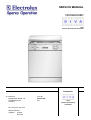
1
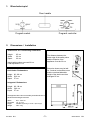
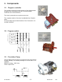
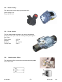
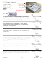
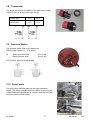
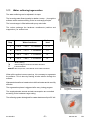
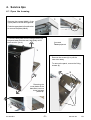
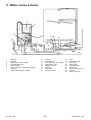
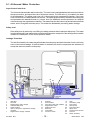
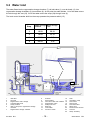
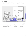
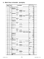
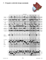
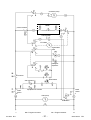
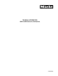
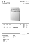
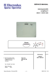
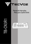
SERVICE MANUAL DISHWASHER with electro mechanical controller Dishwasher © Electrolux Muggenhofer Straße 135 D-90429 Nürnberg Germany Fax +49 (0)911 323 1022 Spares Operation Ausgabe: 03.2003 R.Kurzke Publ.-Nr.: 599 516 423 EN with electro mechanical controller Index 1. Control panel ........................................................................... 3 2. Dimensions / Installation .......................................................... 3 3. Components ........................................................................... 4 3.1 Controller ................................................................................ 4 3.2. Program switch ....................................................................... 4 3.3 Circulation pump ..................................................................... 4 3.4 Drain pump .............................................................................5 3.5 Flow heater .............................................................................5 3.6 Interference filter ...................................................................... 5 3.7 Detergent dispenser ............................................................... 6 3.8 Thermostat .............................................................................. 7 3.9 Pressure switch ....................................................................... 7 3.10 Spray arms .............................................................................7 3.11 Regeneration dosing with condensor ....................................... 8 3.11.1 Water softening/regeneration .................................................. 8 4. 4.1 4.11 4.2 Repair informations .................................................................9 Open the housing .................................................................... 9 Remove the components ......................................................... 10 Position of the components .....................................................11- 13 5.1 5.2 5.3 Water course Scheme............................................................. 14 All-Around Water Protection ....................................................15 Water intake ............................................................................16 Draining .................................................................................. 17 5. 6. Program steps ........................................................................ 18 7. Controller steps ....................................................................... 19 8. Wirings ................................................................................... 21 - 21 03.2003 R.K. -2- 599 516 423 EN 1. Blendenbeispiel Door handle Program controller Program switch 2. Dimensions / Installation Dimensions for Freestanding Dishwasher Height Width Depth 85 cm 60 cm 60 cm The distance between the lower edge of the safety valve and the footprint of the appliance must be 30 cm. Height with worktop removed 82 cm Feet adjustment 1 cm Extension hoses may be laid for 3 metres horizontal at most and the maximal allowable height of the drain hose then averages 85 cm. Built-Under Dishwashers Height Width Depth 82 - 88 cm 59,6 cm 57 cm Integrated Dishwashers Height Width Depth 82 - 88 cm 59,6 cm 57 cm The appliance door can be covered by a wooden/furniture panel of the following dimensions Width Thickness Height Weight 03.2003 R.K. 59,1 - 59,4 cm 1,6 - 2,4 cm variable (depending on niches or plinth height) max. 8 kg -3- 599 516 423 EN 3. Components 3.1. Program controller The operating sequence and the duration of the individual wash programs are controlled by this timer. All electric power consumers are connected there. The timer is powered over a synchronous motor. The complete rotation of the timer is subdivided into 58 switch steps. For each switch step a determined time from 5 seconds to 24 minutes is defined. 3.2. Program switch 3.3. Circulation Pump The circulation pump is driven by an asynchronous motor with an auxiliary winding. The auxiliary winding ist in circuit with a 3 uF capacitor. Speed for rinsing. 2800 1/min. Power output 50 W. 03.2003 R.K. -4- 599 516 423 EN 3.4. Drain Pump The drain pump is driven by a synchronous motor. Power output 26 W. Pump rate 15 l/min. 3.5. Flow Heater The flow heater heats the water to the required temperature. During the wash cycle, water is contantly passing through the flow heater. Power output Resistor Protector Thermal fuse 3.6. 2100 W 25 W 98 °C ± 5 K 260 °C Interference Filter The interference filter is connected in the terminal board parallel to the mains feed. 03.2003 R.K. -5- 599 516 423 EN 3.7 Detergent dispenser Dosing of detergent prewash 10 ml wash 20 - 30 ml Dosing of rinse aid position 1 - 6 2 ml - 7 ml Capacity 140 ml display lack of rinse aid dosing of rinse-aid maximum filling level outlet of rinse-aid detergent tray detergent tray for pre wash coil Spule The detergent compartment 1 is filling corresponding to the set dosing quantity when the door is open. Possibly existing rinse-aid in compartments 2 and 3 flows back into the storage tank of the rinse-aid. The detergent trays are filled up. The door will be closed and the detergent for prewash will be rinsed out through the slots in the detergent dispenser cover. During the washing cycle the coil is switched on and the detergent compartment cover releases the detergent. The rinse-aid flows from compartment 1 into compartment 2. EIN AUS Zeit EIN AUS Zeit EIN AUS Zeit After switching off the coil, the rinse-aid flows from compartment 2 into compartment 3. During the rinse cycle, the coil will be switched on when the rinse is warmed and the rinse-aid runs from compartment 3 into the rinse tank. At the same time, the remaining rinse-aid (15 %) runs from compartment 1 into compartment 2. EIN AUS Zeit EIN AUS Zeit With the coil switched off, the rinse-aid flows from compartment 2 into compartment 3. During the rinse cycle, the coil is always switched on twice. When it is switched on the second time, the remaining rinse-aid flows into the rinse tank. 03.2003 R.K. -6- EIN AUS Zeit 599 516 423 EN 3.8. Thermostat This temperature probe is installed in the drain trough (water collector) and has direct contact with the lye. Switch point 50°C 65°C Reset point 41°C 55°C 3.9. Pressure Switch The pressure switch controls the water level. Without water, contact 11 - 12 is closed. fN Switch point with level Reset point with level 65 mm Ws 45 mm Ws The pressure switch is not adjustable. 3.10. Spray arms The new cutlery basket is placed at the upper diswasher basket. The celling sprayarm sprays the water directly onto the cutlery basket and tguarantees an excellent washing result with the cutlery placed in that basket. upper spray arm lower spray arm 03.2003 R.K. -7- 599 516 423 EN 3.11 Water softening/regeneration The water softening can be adjusted in 4 steps. The incoming water flows (quantity in relation to step ...) through the softener which works according to the ion exchange principle. The ion exchanger is filled with small epoxy resin balls. The resins exchange the hardness constituents (calcium and magnesium), for sodium ions. Step * Water hardness Hardness level 1 < 14°d < 25°F < 2,5 mmol/l I / II 2* < 21°d < 37°F < 3,8 mmol/l III 3 < 28°d < 50°F < 5,0 mmol/l IV 4 < 50°d < 89°F < 9,0 mmol/l IV Regenerierdosierung - factory setting °d - German degree, dimension of water hardness °f -French hardness mmol/l - Millimol per litre, international unit for water hardness When all the sodium ions are used up, it is necessary to regenerate the softener. This is done by flushing a brine solution through the softener. 1 Afterwards the softener is washed out with fresh water and is now fully effective. The regeneration phase is triggered after every rinsing program. The employed water amount and salt consumption are controlled according to the hardness range setting. 1. 2. Enthärter Regenerier-Dosierung The softening system is designed for a water hardness of up to 50 °dH. 03.2003 R.K. -8- 599 516 423 EN 4. Service tips 4.1 Open the housing 1 Remove the screws (Abb.1) of the upper plate on the left and right side. 2 Push the upper plate in front direction to remove the plate (Abb.2). To remove side panel remove fixing screws, pull the panel away from the rear, and gently out of the front trim. (pic.1). You need Torx epuipment 1 Remove the screws (1) to pull the outer door away. To remove the panel, remove the fixing screws (2) . 2 Removing the cover plates of the base area, remove these screwst (Abb1+2). 2 03.2003 R.K. 1 3 -9- 599 516 423 EN 4.11. Remove the panel components Removal of the toggle switches You can, through the lateral hole, release the retention spring by pressing it in, for example with a bent-out paper-clip. In this way, the toggle can be pulled off easily. The sequential circuit program is screwed down on two places. After releasing the screws and removing the toggle, it can be taken off easily. The LEDs for display are installed (depending on the equipment) in the frame and can be unclicked. 1 To remove the program selector, the support frame (1) must be unclicked. By unclicking both locking lugs you have access to the switch. 03.2003 R.K. - 10 - 2 599 516 423 EN 4.2 Position of Components Detergent dispenser (1) Spray arms (2) Roof-mounted shower (3) Salt container (4) Filter (5) 3 4 5 2 Type plate (6) 1 6 2 1 Program switch (1) Program controller (2) 1 Detergent dispensert (3) 2 3 Thermostat (4) Drain pump (5) Pressure switch (6) 4 03.2003 R.K. - 11 - 5 6 599 516 423 EN Back side view - Flow heater (1) Terminal box (2) - Inlet hose (3) Drain hose (4) - Water inlet for above spray arm (5) 5 1 4 2 Removing the detergent dosage chamber: - 3 1 disengage locking tabs (1), disconnect hoses (2) holding the top of the chamber, pull upwards disengaging it from the softener. 2 Removing the softener unit : - remove the securing nut located under the salt cap. press softener (1) down and remove it through the front from the base area CAUTION if accessible release reed switch. 1 03.2003 R.K. - 12 - 599 516 423 EN Removing the base : - remove side panels, rear panel and plinth panel gently release base fixing clips with a screwdriver (figure) take off base carefully and release circulation pump, electronic and heater relay disconnect the float switch With - base removed, following components are accessible: Drain pump (1) Circulation pump (2) Flow heater (3) Thermostat (4) Pressure switch (5) 4 1 5 2 3 03.2003 R.K. - 13 - 599 516 423 EN 5. Water course scheme 22 3 2 21 7 4 15 23 24 21 1 12 6 5 9 11 8 18 16 17 10 20 14 1 2 3 4 5 6 7 Inlet valve Air break Regeneration water dosage Overflow safety level Safety overflow Inlet to sump from regeneration dosage chamber Regeneration dosage chamber 03.2003 R.K. 8 9 10 11 12 13 14 15 16 Softener 17 Salt container Non-return valve salt container 18 19 Regeneration valve 20 Safety inlet hose 21 Base tray 22 Float switch 23 Pressure switch 24 - 14 - 19 13 Filter Circulation pump Flow heater Drain pump Non-return valve Spray arms Roof-mounted shower Tub vent Sump assembly 599 516 423 EN 5.1 All-Around Water Protection Aqua-Control Inlet Hose The inlet hose has a double-wall construction. The inner hose is equipped with a flow restrictor built into the tap connection, and has a flow rate of 4 litres per minute. The inlet valve (1) is located in the base of the dishwasher. The safety outer hose (12) is connected to the regeneration chamber. If the inner hose should burst, the water passes into the tub. The safety pressure switch activates the drain pump and decreases the waterlevel down to normal level. An additional overflow protection is a defined overflow through the regeneration chamber. The water flows into the bottom tray and activates the float switch, which energises the drain pump. This drains the dishwasher preventing water damage. Safety level If the safety level is reached by over-fillling, the safety pressure switch starts the drain pump. The water is only drained until it has reached the normal level because the reset point of the safety pressure switch is above the switchpoint of the normal pressure switch. Leakage Protection The anti-flood switch in the base tray will activate the drain pump and drain the water from the tub in the event of an internal leakage. If the float switch is activated, all electric components are switched off except the electronic and the drain pump. 22 2 7 3 21 23 4 15 24 1 12 6 5 11 8 9 7 17 10 20 19 14 13 1 2 3 4 5 6 18 16 Inlet valve Air break Regeneration water dosage Overflow safety level Safety overflow Inlet to sump from regeneration dosage chamber Regeneration dosage chamber 03.2003 R.K. 8 9 10 11 12 13 14 15 16 Softener 17 Salt container Non-return valve salt container 18 19 Regeneration valve 20 Safety inlet hose 21 Base tray 22 Float switch 23 Pressure switch 24 - 15 - Filter Circulation pump Flow heater Drain pump Non-return valve Spray arms Roof-mounted shower Tub vent Sump assembly 599 516 423 EN 5.2 Water Inlet The water flows into the regeneration dosage chamber (7) via inlet valve (1), over air break (2), into regeneration dosage chambers (3) into softener (8). At this point the water divides. 1/4 of the water enters the tub through the vent (23). 3/4 of the water enters the sump (24) through hose (6). The level control chamber built into the sump operates the pressure switch (15). Step Water through softener Water through vent 1 80 % 20 % 2 90 % 10 % 3 100 % 0% 4 100 % 0% 22 2 7 3 21 23 4 15 24 1 12 6 5 11 8 9 7 17 10 18 20 19 14 13 1 2 3 4 5 6 16 Inlet valve Air break Regeneration water dosage Overflow safety level Safety overflow Inlet to sump from regeneration dosage chamber Regeneration dosage chamber 03.2003 R.K. 8 9 10 11 12 13 14 15 Softener 16 Salt container 17 Non-return valve salt container 18 Regeneration valve 19 Safety inlet hose 20 Base tray 21 Float switch 22 Pressure switch 23 24 - 16 - Filter Circulation pump Flow heater Drain pump Non-return valve Spray arms Roof-mounted shower Tub vent Sump assembly 599 516 423 EN 5.3 Draining During the wash cycle the water is pumped out at various stages. First the draining water cleans the filters (16). The filters are open at the bottom which allows any soilage to be rinsed off sufficiently. There is a non-return valve (20) at the inlet connection to the drain pump (19). This valve prevents the water 22 2 3 7 21 23 4 15 24 1 12 6 5 11 8 9 7 17 10 20 19 14 13 1 2 3 4 5 6 18 16 Inlet valve Air break Regeneration water dosage Overflow safety level Safety overflow Inlet to sump from regeneration dosage chamber Regeneration dosage chamber 03.2003 R.K. 8 9 10 11 12 13 14 15 Softener 16 Salt container 17 Non-return valve salt container 18 Regeneration valve 19 Safety inlet hose 20 Base tray 21 Float switch 22 Pressure switch 23 24 - 17 - Filter Circulation pump Flow heater Drain pump Non-return valve Spray arms Roof-mounted shower Tub vent Sump assembly 599 516 423 EN 6. Work flow schematic (example) Step Function Pumping out Filling Pumping out Filling Filling (Filling) Pumping out Pumping out Pumping out Break/pause Pumping out Break/pause Filling Filling Washing Washing Heating Washing Detergent Washing Washing Heating Washing Filling Filling Washing Filling Filling Washing Washing Break/pause Break/pause Pumping out Time in sec. Washing Filling Filling Filling Washing Washing Washing Heating Clear rins. Washing Heating Clear rins. Pumping out Break/pause Regeneration Break/pause Pumping out Break/pause Pumping out Filling Pumping out Filling Filling Filling Pumping out Filling Filling Regeneration Pumping out Pumping out Filling Filling Filling Detergent Washing Washing Heating Washing Washing Washing Heating Clear rins. Washing Washing Washing Pumping out 03.2003 R.K. - 18 - 599 516 423 EN 7. Program controller steps (example) 03.2003 R.K. - 19 - 599 516 423 EN 8. Wirings (examples) circulation pump Heater pressure switch inlet valve CTL-Motor regeneration valve Detergent dispenser door switch on/off switch on/off switch equipment-on indicator drain pump float switch b7 = Program selector b3 = Program controller 03.2003 R.K. - 20 - 599 516 423 EN circulation pump Heater pressure switch inlet valve CTL-Motor regeneration valve Detergent dispenser door switch Reed switch salt indication on/off switch equipment-on indicator on/off switch drain pump float switch b7 = Program selector b3 = Program controller 03.2003 R.K. - 21 - 599 516 423 EN