1
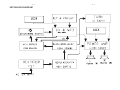
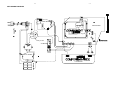
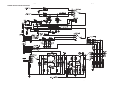
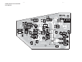
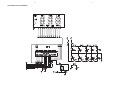
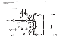
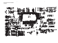
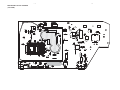
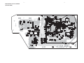
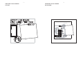
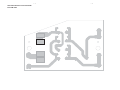
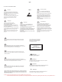
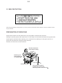
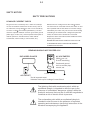
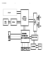
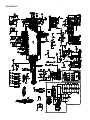
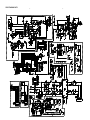
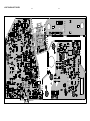
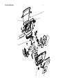
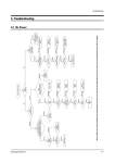
CD Soundmachine
AZ1837/55/73
It is only for serial number :NSxxxxxxxxxxx
TABLE OF CONTENTS
Page
Specifications .......................................................................... 1
Software Version Checking ..................................................... 2
Set Block Diagram ................................................................3-1
Set Wiring Diagram ..............................................................3-2
Power Board ............................................................................4
VR Board ................................................................................. 5
LCD Board ..............................................................................6
Main & USB Jack & Rect. Board ............................................. 7
Set Mechanical Exploded View & Parts List ........................... 8
©
Copyright 2012 Philips Consumer Electronics B.V. Eindhoven, The Netherlands
All rights reserved. No part of this publication may be reproduced, stored in a retrieval system or
transmitted, in any form or by any means, electronic, mechanical, photocopying, or otherwise without
the prior permission of Philips.
Published by LX 1231 Service Audio
Version 1.1
Printed in The Netherlands
Subject to modification
3141 785 34571
1-1
SPECIFICATIONS
Dimensions (L x W x H)
341mm x 236mm x 122mm
W e ig h t
1.8 kg
P o w e r su p p ly
DC 9V 1.5 A
110V-127V,60HZ;
220-240V, 50HZ
Power consumption
Active <12 W
P o w e r o u tpu t
2 x 1 W RMS
Operating temperature range
-10 °C - 50 °C
14 °F -122 °F
USB playability information
Compatible USB devices:
•
•
•
memory cards (requires an additional card reader to work with this
apparatus)
Supported formats:
•
•
•
•
•
•
•
•
MP3 bit rate (data rate): 32-320 Kbps and variable bit rate
WMA v9 or earlier
Directory nesting up to a maximum of 8 levels
Number of albums/ folders: maximum 99
Number of tracks/titles: maximum 999
ID3 tag v2.0 or later
File name in Unicode UTF8 (maximum length: 128 bytes)
•
Unsupported formats:
Empty albums: an empty album is an album that does not contain MP3/
•
•
•
•
1-2
PCBS LOCATION
CD DOOR
USB PCB
RIGHT CABINET
POWER PCB
TOP CABINET
CD MECHANISM DA11B3VZSS (SANYO)
VR PCB
LCD PCB
MAIN PCB
BOTTOM CABINET
RECT. PCB
VERSION VARIATIONS
AZ1837
Type / Version
Board in use
Service policy
/05
/12
/37
/55
/58
/73
C
C
M/C
M/C
C
C
MAIN PCB
M/C
M/C
RECT.PCB
M/C
M/C
CD MECHANISM DA11B3VZSS(SANYO)
M
M
LCD PCB
C
C
USB PCB
POWER PCB
V R PCB
BOTTOM CABINET
* TIPS: C -- Component Lever Repair.
M -- Module Lever Repair
X -- Used
/98
C
C
Remark: For Europe, service policy should be OCX.
3-1
SET BLOCK DIAGRAM
3-1
3-2
3-2
SET WIRING DIAGRAM
POWER BOARD
MAIN BOARD
only for /55
VR BOARD
RECT. BOARD
LCD BOARD
4-1
POWER BOARD-CIRCUIT DIAGRAM
4-1
4-2
POWER BOARD-LAYOUT DIAGRAM
TOP VIEW
4- 2
4-3
POWER BOARD-LAYOUT DIAGRAM
BOTTOM VIEW
4-3
5-1
VR BOARD-CIRCUIT DIAGRAM
5-1
5-2
VR BOARD-LAYOUT DIAGRAM
TOP VIEW
5-2
VR BOARD-LAYOUT DIAGRAM
BOTTOM VIEW
6-1
LCD BOARD-CIRCUIT DIAGRAM
6-1
6-2
LCD BOARD-LAYOUT DIAGRAM
6-2
7-1
MAIN BOARD-CIRCUIT DIAGRAM
(AMP PART)
7-1
7 -2
MAIN BOARD-CIRCUIT DIAGRAM
(BUFFER PART)
7-2
7-3
MAIN BOARD-CIRCUIT DIAGRAM
(CD PART)
7-3
7-4
MAIN BOARD-CIRCUIT DIAGRAM
(TUNER PART)
7-4
7-5
MAIN BOARD-LAYOUT DIAGRAM
(TOP VIEW)
7-5
7-6
MAIN BOARD-LAYOUT DIAGRAM
(BOTTOM VIEW)
7-6
7-7
USB BOARD-CIRCUIT DIAGRAM
7-7
7-8
7-8
USB BOARD-LAYOUT DIAGRAM
TOP VIEW
USB BOARD-LAYOUT DIAGRAM
BOTTOM VIEW
86%-$&.
7-9
RECTIFIER BOARD-CIRCUIT DIAGRAM
7-9
7 - 10
RECTIFIER BOARD-LAYOUT DIAGRAM
TOP VIEW
7 - 10
7 - 11
RECTIFIER BOARD-LAYOUT DIAGRAM
BOTTOM VIEW
7 - 11
8-1
SET MECHANICAL EXPLODED VIEW
8-1
8-2
MECHANICAL & ACCESSORIES PARTS LISTRQO\IRUVHULDOQXPEHU16[[[[
1
10
11
12
16
996510030502
! 996510031044
996510030538
996510031046
996510031043
17
18
19
2
2
996510030534
996510031038
996510030527
996510031048
996510032562
VOL-PCB-BRACKET
VR PCB
VOL. DECO RING W/PLATE
CD DOOR /55
CD DOOR /73
20
20
21
22
23
996510030549
996510032712
996510031031
996510031032
996510031058
LENS LCD /55
LENS LCD /73
FUNCTION BUTTON A
FUNCTION BUTTON B
LCD PCB /55
23
25
26
27
28
996510032713
996510031042
996510030531
! 996510016704
! 994000005096
LCD PCB /73
MAIN PCB
AC SOCKET HOLDER
2PINS AC SOCKET
TRANSFOMER EI-41 120/230V /55
28
29
3
31
32
! 996500039377
996510021543
996510000931
996510000874
996510031023
TRANSFOMER EI-41 230V 50Hz 9V /73
AC SELECTOR COVER
CD DOOR GEAR
VOLTAGE SELECTOR WS-12J01-GC7
BATTERY SPRING
33
34
36
37
38
996510031021
996510030509
996510031029
996510030512
996510031059
BATTERY SPRING
AC SELECTOR PLATE
RECT PCB
SOUND PIPE (L)
LENS PANEL
4
40
41
45
47
994000003393
996510030507
994000001409
996510030529
996510030517
ROD ANTENNA 2-SECTIONS L=420MM
CD DOOR SPRING
CD DOOR GEAR HOLDER
TUNING KNOB
ROTATE BRACKET R
49
5
50
51
53
996510031037
996510031045
994000001417
994000001422
996510030541
RIGHT CABINET
TOP CABINET
DUST COVER FOR DA12N
CD DOOR SWITCH 1P1T
TUNING GEAR B
54
56
57
58
6
996510030518
996510030528
996510030505
994000005115
996510030532
TUNING GEAR C
CD DAMPER GRN COLOR 658N
CD MECHANISM DA11B3VZSS
CD DAMPER BLACK 658PH
SWITCH KNOB
61
62
64
65
66
996510031022
996510031041
996510031027
996510031036
996510031034
FUNCTION BUTTON E
FUNCTION BUTTON D
BATTERY DOOR
BATTERY SPRING
BATTERY SPRING
Note:
HANDLE
POWER PCBA
77MM SPEAKER 8R 1W 3INCH
LEFT CABINET
VOLUME KNOB
Only these parts mentioned in the list are
normal service parts.
8-3
MECHANICAL & ACCESSORIES PARTS LISTRQO\IRUVHULDOQXPEHU16[[[[
68
68
69
7
70
996510031028
996510032559
996510030516
996510030537
996510031035
BOTTOM CABINET /55
BOTTOM CABINET /73
SOUND PIPE (R)
ROTATE BRACKET L
FUNCTION BUTTON C
8
A
ACCOIL1
ACCOIL1
LINE10
996510031039
996510030536
! 996510018690
! 996510000876
994000001423
USB PCB
TUNING GEAR A
1.5M VDE POWER CORD /55
5 FT VDE APPRROVED POWER CORD /73
16P FFC L=70MM P=1MM
LINE6
LINE7
RC
! 996510000935
996510001906
996510032558
2 PINS PLUG ADAPTOR
AUX STEREO CORD BLACK
REMOTE CONTROL
ELECTRICAL PARTSLIST
MAIN BOARD ASSEMBLY
CN105
D101
D104
D105
D106
996510021555
996510010774
996510010774
9 9 6 5 1 0 0 1 0 77 4
996510010774
FFC SOCKET P1.0MM (ANGLE TYPE)
DIODE 1N4148 FDLL4148
DIODE 1N4148 FDLL4148
DIODE 1N4148 FDLL4148
DIODE 1N4148 FDLL4148
D107
D108
D109
D300
D301
996510010774
996510010774
996510010774
996510010774
996510010774
DIODE 1N4148 FDLL4148
DIODE 1N4148 FDLL4148
DIODE 1N4148 FDLL4148
DIODE 1N4148 FDLL4148
DIODE 1N4148 FDLL4148
IC101
IC102
IC103
IC104
IC201
996510021675
996510021673
9 96510031019
996510003844
996510018432
IC M5673 128P LQFP
IC SCA4720
IC PROGRAMMED A25L020Z01A
I.C. VOLTAGE REGULATOR
IC D2822N
IC300
Q101
Q102
Q103
Q104
9 9 65 1 0 0 3 1 0 3 3
996510024762
996510012833
9 9 6 5 1 0 0 0 3 71 8
996510024762
IC SA2111C SDIP-24
TRANSISTOR KTC9014S
TRANSISTOR BC857B
TRANSISTOR KTC-8550C
TRANSISTOR KTC9014S
Q105
Q106
Q107
Q109
Q110
996510024762
996510024762
996510024762
996510003718
996510024762
TRANSISTOR KTC9014S
TRANSISTOR KTC9014S
TRANSISTOR KTC9014S
TRANSISTOR KTC-8550C
TRANSISTOR KTC9014S
Q111
Q112
Q113
Q114
Q115
996510012833
996510012833
996510030525
996510030525
996510024762
TRANSISTOR BC857B
TRANSISTOR BC857B
TRANSISTOR BC817-40 SOT23
TRANSISTOR BC817-40 SOT23
TRANSISTOR KTC9014S
Q116
Q117
Q207
Q208
Q311
996510024762
996510012833
996510024762
996510024762
996510024762
TRANSISTOR KTC9014S
TRANSISTOR BC857B
TRANSISTOR KTC9014S
TRANSISTOR KTC9014S
TRANSISTOR KTC9014S
Note:
Only these parts mentioned in the list are
normal service parts
parts.
8-4
ELECTRICAL PARTSLIST RQO\IRUVHULDOQXPEHU16[[[[
MAIN BOARD ASSEMBLY
Q312
X101
ZD101
996510024762
996510011310
994000005744
TRANSISTOR KTC9014S
CERAMIC RESONATORZTA16.9344MHZ
ZENER DIODE 5V1 1/2W
ELECTRICAL PARTSLIST
POWER BOARD ASSEMBLY
D201
D202
D203
D207
D208
996510010774
996510010774
996510010774
996510010774
996510010774
DIODE 1N4148 FDLL4148
DIODE 1N4148 FDLL4148
DIODE 1N4148 FDLL4148
DIODE 1N4148 FDLL4148
DIODE 1N4148 FDLL4148
D210
D213
DZ201
DZ202
JK201
996510010774
996510010774
996510012835
996510011336
996510003840
DIODE 1N4148 FDLL4148
DIODE 1N4148 FDLL4148
ZENER DIODE 5V6 1/2W (TC5V6)
ZENER DIODE 7V5 1/2W (TC7V5)
3.5MM STEREO JACK
Q201
Q202
Q203
Q204
Q210
996510001414
996510024762
996510012833
996510003717
996510030524
TRANSISTOR KTB772 (KEC) TAPE
TRANSISTOR KTC9014S
TRANSISTOR BC857B
TRANSISTOR KTD882 (KEC)
TRANSISTOR BC807-40 SOT23
Q212
R282
R283
996510024762
996510031047
996510031047
TRANSISTOR KTC9014S
FERRITE BEAN 2K7R 100MHZ
FERRITE BEAN 2K7R 100MHZ
USB & VR & LCD BOARD ASSEMBLY
USBJACK
VR201
IC600
LCD
SW600
996510001071
996510030514
996510025149
996510031061
996500039269
USB JACK 4P ANGLE TYPE
ROTARY VOLUME F-122KGP
IC ET8861M LCD DRIVER
LCD DISPLAY GS-35468-TRPC
TACT SWITCH
SW601
SW602
SW603
SW604
SW605
996500039269
996500039269
996500039269
996500039269
996500039269
TACT SWITCH
TACT SWITCH
TACT SWITCH
TACT SWITCH
TACT SWITCH
SW606
SW607
SW608
SW609
996500039269
996500039269
996500039269
996500039269
TACT SWITCH
TACT SWITCH
TACT SWITCH
TACT SWITCH
RECT BOARD ASSEMBLY
C805
D801
D802
D803
D804
994000003217
996510011339
996510011339
996510011339
996510011339
F801
! 996510018427
Note:
AL.E.CAP 3300UF 25V
DIODE 1N4003
DIODE 1N4003
DIODE 1N4003
DIODE 1N4003
FUSE 1.6A 250V D5X20MM
Only these parts mentioned in the list are
normal service parts.
AZ1837
CD Soundmachine
all version
It is only for serial number XUxxxxxxxx
TABLE OF CONTENTS
Page
Version Variation..................................................................... 1-2
Technical specification ..................................................1-3..1-14
Safety instruction.................................................................... 2-1
ESD protection........................................................................2-2
Set Block diagram ........................................................... .......3-1
Set Wiring diagram ............................................................. ....4-1
Circuit diagram.................................................................5-1..5-3
Layout diagram.................................................................6-1..6-2
Mechanical Exploded view..........
.......................................... .....7-1
© Copyright
2012 Philips Consumer Electronics B.V. Eindhoven, The Netherlands
All rights reserved. No part of this publication may be reproduced, stored in a retrieval
system or transmitted, in any form or by any means, electronic, mechanical, photocopying,
or otherwise without the prior permission of Philips.
Published by LX 1225 Service Audio
Version 1.0
Subject to modification
3141 785 38280
2-1
2.0 SAFTETY INSTRUCTIONS
GB
NL
ESD
WARNING
Alle IC’s en vele andere halfgeleiders zijn
gevoelig voor electrostatische ontladingen
(ESD).
Onzorgvuldig behandelen tijdens reparatie kan
de levensduur drastisch doen verminderen.
Zorg ervoor dat u tijdens reparatie via een
polsband met weerstand verbonden bent met
hetzelfde potentiaal als de massa van het
apparaat.
Houd componenten en hulpmiddelen ook op
ditzelfde potentiaal.
All ICs and many other semi-conductors are
susceptible to electrostatic discharges (ESD).
Careless handling during repair can reduce life
drastically.
When repairing, make sure that you are
connected with the same potential as the mass
of the set via a wrist wrap with resistance.
Keep components and tools also at this
potential.
F
ATTENTION
Tous les IC et beaucoup d’autres
semi-conducteurs sont sensibles aux
décharges statiques (ESD).
Leur longévité pourrait être considérablement
écourtée par le fait qu’aucune précaution n’est
prise à leur manipulation.
Lors de réparations, s’assurer de bien être relié
au même potentiel que la masse de l’appareil et
enfiler le bracelet serti d’une résistance de
sécurité.
Veiller à ce que les composants ainsi que les
outils que l’on utilise soient également à ce
potentiel.
WAARSCHUWING
D
I
WARNUNG
Alle ICs und viele andere Halbleiter sind
empfindlich gegenüber elektrostatischen
Entladungen (ESD).
Unsorgfältige Behandlung im Reparaturfall kan
die Lebensdauer drastisch reduzieren.
Veranlassen Sie, dass Sie im Reparaturfall über
ein Pulsarmband mit Widerstand verbunden
sind mit dem gleichen Potential wie die Masse
des Gerätes.
Bauteile und Hilfsmittel auch auf dieses gleiche
Potential halten.
AVVERTIMENTO
Tutti IC e parecchi semi-conduttori sono
sensibili alle scariche statiche (ESD).
La loro longevità potrebbe essere fortemente
ridatta in caso di non osservazione della più
grande cauzione alla loro manipolazione.
Durante le riparazioni occorre quindi essere
collegato allo stesso potenziale che quello della
massa dell’apparecchio tramite un braccialetto
a resistenza.
Assicurarsi che i componenti e anche gli utensili
con quali si lavora siano anche a questo
potenziale.
GB
Safety regulations require that the set be restored to its original
condition and that parts which are identical with those specified,
be used.
“Pour votre sécurité, ces documents
doivent être utilisés par des spécialistes agréés, seuls habilités à réparer
votre appareil en panne”.
NL
Veiligheidsbepalingen vereisen, dat het apparaat bij reparatie in
zijn oorspronkelijke toestand wordt teruggebracht en dat onderdelen,
identiek aan de gespecificeerde, worden toegepast.
CLASS 1
LASER PRODUCT
3122 110 03420
F
Les normes de sécurité exigent que l’appareil soit remis à l’état
d’origine et que soient utiliséés les piéces de rechange identiques
à celles spécifiées.
GB
Warning !
Invisible laser radiation when open.
Avoid direct exposure to beam.
D
Bei jeder Reparatur sind die geltenden Sicherheitsvorschriften zu
beachten. Der Original zustand des Geräts darf nicht verändert werden;
für Reparaturen sind Original-Ersatzteile zu verwenden.
I
Le norme di sicurezza esigono che l’apparecchio venga rimesso
nelle condizioni originali e che siano utilizzati i pezzi di ricambio
identici a quelli specificati.
"After servicing and before returning set to customer perform a
leakage current measurement test from all exposed metal parts to
earth ground to assure no shock hazard exist. The leakage current
must not exceed 0.5mA."
S
Varning !
Osynlig laserstrålning när apparaten är öppnad och spärren
är urkopplad. Betrakta ej strålen.
SF Varoitus !
Avatussa laitteessa ja suojalukituksen ohitettaessa olet alttiina
näkymättömälle laserisäteilylle. Älä katso säteeseen!
DK Advarse !
Usynlig laserstråling ved åbning når sikkerhedsafbrydere er
ude af funktion. Undgå udsaettelse for stråling.
Caution: These servicing instructions are for use by qualified service personnel only.
To reduce the risk of electric shock do not perform any servicing other than that contained in the operating instructions unless you are qualified to do so.
2-2
2.1 ESD PROTECTION
Whenthepowersupplyisbeingturnedon,youmaynotremovethislasercautionslabel.Ifitremoves,radiationoflaser
maybereceived.
PREPARATIONOFSERVICING
PickupHeadconsistsofalaserdiodethatisverysusceptibletoexternalstaticelectrocity.
Althoughitoperatesproperlyafterreplacement,ifitwassubjecttoelectrostaticdischargeduringreplacement,
itslifemightbeshortened.Whenreplacing,useaconductivemat,solderingironwithgroundwire,etc.to
protectthelaserdiodeformdamagebystaticelectricity.
Andalso,theLSIandICaresameasabove.
Groundconductive
wriststrapforbody.
Solderingiron
withgroundwire
orceramictype
1M
Conductivemat
Thegroundresistance
betweenthegroundline
andthegroundislessthan10
2-3
SAFTY NOTICE
SAFTY PRECAUTIONS
LEAKAGE CURRENT CHECK
Plug the AC line cord directly into a 120V AC outlet (do
Measure the AC voltage across the 1500
not use an isolation transformer for this check). Use an
AC voltmeter, having 5000 per volt or more sensitivity.
The test must be conducted with the AC switch on and
then repeated with the AC switch off. The AC voltage
Connect a 1500
indicated by the meter may not exceed 0.3V.A reading
10W resistor,paralleled by a 0.15uF
resistor.
150V AC capacitor between a knomn good earth ground
(water pipe, conduit, etc.) and all exposed metal parts of
exceeding 0.3V indicates that a dangerous potential
exists, the fault must be located and corrected.
cabinet (antennas, handle bracket, metal cabinet
screwheads, metal overlays, control shafts, etc.).
Repeat the above test with the DVD VIDEO PLAYER
power plug reversed.
NEVER RETURN A DVD VIDEO PLAYER TO THE
CUSTOMER WITHOUT TAKING NECESSARY
CORRECTIVE ACTION.
READING SHOULD NOT EXCEED 0.3V
AC VOLTMETER
DVD VIDEO PLAYER
(5000 per volt
or more sensitivity)
1500
10W
AC OUTLET
Good earth ground
such as a water pipe,
conduit, etc.
0.15uF 150V AC
Test all exposed metal.
Voltmeter Hook-up for Leakage Current Check
The lightning flash with arrowhead symbol, within an
equilateral triangle, is intended to alert the user to the
presence of uninsulated "dangerous voltage" within the
product's enclosure that may be of sufficient magnitude to
constitute a risk of electric shock to persons.
The exclamation point within an equilateral triangle is
intended to alert the user to the presence of important
operating and maintenance (servicing) instructions in the
literature accompanying the appliance.
BLOCK DIAGRAM
3-1
3-1
WIRING DIAGRAM
4-1
4-1
CIRCUIT DIAGRAM - PART 1
5-1
5-1
CIRCUIT DIAGRAM - PART 2
5-2
5-2
LAYOUT DIAGRAM - TOP VIEW
6-1
6-1
LAYOUT DIAGRAM - BOTTOM VIEW
6-2
6-2
EXPLODED VIEW DIAGRAM
7-1
7-1
15
27
17
15
16
18
19
11
20
21