1
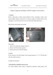
Chery QQ Service Manual
Chassis System
Chapter two Tests and Adjustments of
Four-Wheel Positioning
Section One: Basic Tests and Checks
Preparations prior to adjustments
I. Checks prior to adjustments
(1)Checks on tire air pressure
(2)Checks on car body
1、Check the tire air pressure,
and adjust to the specified pressure.
Standard air pressure for tires (kPa)
Item
Zero load
Front wheel
220
Rear wheel
220
Spare tire
250
2、Check the spacing of front wheel bearings, and replace the front wheel bearings when
necessary;
3、Check the status of the wheel outer rims, as well as the status of the wheel sections and
tires;
4、Check to see if the ball joint of the horizontal draw-bar for turning is too loose;
5、Place the car on a leveled ground without any luggage or passenger;
6、Make sure that the left and right heights from the wheel center line to the dasher do not
exceed the standard heights;
7、Check to see if the absorber performance is normal.
II. Rim section and tire
1、Visual checks
Check the tires and rim sections, and make proper
replacements if any cracks, damages, deformations
or other defects are detected on the rim sections or
tires.
Tears and wears of tire
- 58 -
Chery Automobile Co., Ltd
Chery QQ Service Manual
Chassis System
2、Tire tears and wears
(1)Check the depth of the remaining tire
textures.
The depth of the remaining tire textures (as shown
in the Figure)
Standard tires: 1.6mm min.
Snow ground tires: 50 % tire textures
Wear position
(2)In the case that the wear-and-tear indication Wear position
belt is exposed, the tire must be replaced.
Indication points for tire tears and wears
3、Abnormal tears and wears of tires
The abnormal tears and wears of the tires as
shown in the right figure might occur. Refer to the
following table for the possible causes and the
approaches for handling the trouble.
bi-wear
Center wear
Toe-in and toe-out wear Unilateral-wear
Tears and wears of tire
(a)
(b)
(c)
Possible causes
* Insufficient tire air pressure
(tears and wears on both sides)
* Turning in fast speed
* Tire positions not re-adjusted
* Excessively high tire air pressure
* Tire positions not re-adjusted
* Toe-in incorrect
* Camber angle incorrect
* Suspension system defective
(d)
* Tires not balanced
* Brake drum or disk not circular
* Other mechanic troubles
* Tire positions not re-adjusted
Approaches for handling
* Test and adjust tire air pressure
* Slow down car speed
* Re-adjust tire positions
* Test and adjust tire air pressure
* Re-adjust tire positions
* Adjust the toe-in
* Adjust, repair or replace the parts
of the axle and suspension system
* Repair or replace the suspension
system
* Make dynamic balance of tires or
replace the tire
* Make alignment or replacements
* Make alignment or replacements
* Readjust the tire positions
- 59 -
Chery Automobile Co., Ltd
Chery QQ Service Manual
Chassis System
4、Points of attention for the rim sections and tires
(1)Do not use the under-standard rim sections or tires;
(2)The aluminum alloy rims are easy to be damaged by scraps. Please use soft cloth
when doing the cleaning. Never try to use steel brushes. If steam is used for cleaning the
car, do not allow the boiling water to contact the rim sections;
(3)In the case that some alkali chemical compounds (such as mud water, road surface
mud, etc.) stain on the aluminum alloy rim sections, use the neutralizing agents to clean
them off as soon as possible so as to avoid the rim sections from being damaged.
5、Tire replacements
(1)Before installing the air valve nozzle, first check to see if the air valve opening on the
tire is smooth and free of rags. Then apply some glycerin onto the surface of the air valve
nozzle rubber or dip the air valve nozzle in the glycerin. Use the special tools to exert the
air pressure of 200—400N so as to allow the positioning ring of the air valve nozzle to pass
the hole on the wheel which complete the installation and positioning (soap solution can be
used to substitute glycerin);
(2)Before installing the tires, apply glycerin or soap solution along the tire rings. Make
sure that when there are light indication spot marks on the rims, the test marks for tire
balance should be aligned with these light indication spot marks. When there are not light
indication spot marks on the rim, the dynamic balance test marks of the tire should be
aligned with the air valve nozzle position. If there are neither light indication spot marks
on the rim nor dynamic balance test marks on the tire, but there are static balance test
marks on the tire, make sure that the air valve nozzle is aligned with the static balance test
marks.
6、Tire pressure
Check the air pressures of all the tires (including the
spare tire) with the barometer. Make proper adjustments
if the air pressure does not meet the specifications. Strictly
follow the specified air pressure in filling the tires with air.
During the air filling, the air pressure should not exceed the
nominal air pressure by 10 %. The tire with filled air should
be placed separate from the wheel mounted on the car. Before
doing the positioning of the four wheels, please check the air
pressures of the four wheels and make proper adjustments
so as to meet the specified air pressure.
7、Air leakage
Make sure there is no air leakage at the air valve.
Checks of air valve nozzles
- 60 -
Chery Automobile Co., Ltd
tyre
air hole
Chery QQ Service Manual
Chassis System
8、Rim sections and tires non-circularity
(1)Lift the car and support it securely;
(2)Place the probe of the dial gauge on the rim
section and measure the extent of non-circularity for
each turning of a circle.
Limit for non-circularity: Unit mm
Longitudinal 1.5(0.06)
Sideways
2.5(0.10) steel rim section
2.0(0.08) aluminum rim section
Inspection on the tire non-circularity
(3)Replace the tire if necessary
9、Readjustments of tire positions
In order to extend the operational life of tires and to
determine the tears and wears of the tires, readjustments
of tire positions should be carried out for every 6,000km
(3,750 miles) of driving.
As shown in the Figure:
Readjustment of tire positions
Attention:
* Best-quality tires must be used for the front wheels;
* After readjustments of tire positions, make sure that the air pressures for the tires are
adjusted to the specified air pressure values.
10、Adjustment of tire balance
After the tires are filled with air, fix the protective
capsfor the air valve nozzles tightly and then make the
testson dynamic balance. Place the balance blocks with
appropriate weights on the inner and outer edges of the
rims as required. According to the specifications, the
imbalance of the final assembly should be no larger than
100g/cm, which is approximately equal to the 5g balance
blocks on the inner and outer edges of the rims. It should
be noted that at most one balancing block is allowed to be
placed on each side of each wheel, with the maximum mass no larger than 70g. During the
process of assembling, excessively heavy shocks should be avoided to the balancing
blocks. In the case that excessive shocks are felt, the balancing blocks should be replaced
in time. The balance blocks taken down in the replacement should not be used again.
- 61 -
Chery Automobile Co., Ltd
Chery QQ Service Manual
Chassis System
11、Installation
(1) When making the assembly of the
outboa
wheels and tires, first fix the wheel screws onto
block
the hubs manually and tighten them slightly.
Then use special tools to tighten the screws in
the diagonal sequence till the specified torque
block
of 110±10N.m is applied. It is not allowed to
use impact wrenches that might cause damages
to the wheels, or insufficient tightness or excessive
tightness. It is not allowed to apply lubricating grease onto the wheel screws. (For the
completed assembly of wheels and tires, the wheel screws should be re-tightened after the
car runs for 100km so that the specified torque is assured. The checks on the torque of the
fixing screws are one of the routine maintenance items).
(2)
When tightening the screw nuts, the
cross approach is applied. The extent of tightness
should be close to each other, and the wheels should
be able to turn freely. When the final tightening is
made, the wheels should be positioned on the ground.
(3)Install the decorated covers or place the decorative covers as needed. When the
clip-type decorative covers are installed, they should be driven in either with hands or by
way of rubber hammering tools.
III.
Checks on the looseness of wheel bearings
1、Check the axial spacing of the bearings
Maximum: 0.05mm
2、Check the bias of the bridge hub
Maximum: 0.05mm
IV.
Checks on the looseness of front suspension system
V.
Checks on the looseness of turning transmission rod system
VI.
Checks on ball joint looseness
VII. Checks on the normal performances of absorbers
- 62 -
Chery Automobile Co., Ltd
Chery QQ Service Manual
Chassis System
1、Check to see if there is any oil leakage;
2、Check to see if there are any tears and wears of the assembly sheaths;
3、Check the resistance of the absorbers. Make proper replacement if any incompliance is
detected.
Section Two: Positioning of Rear Wheels
It is recommended to use the four-wheel positioning device for the chassis of this car model,
which applies the positioning approach by way of axis thrust.
In the position adjustments by way of axis thrust, the toe-in of the rear wheels may have
impacts upon the toe-in of the single front wheel. Therefore, when doing the four-wheel
positioning, the adjustments of the rear wheels are generally done before the adjustments of
the front wheels. Besides, the camber angle of the rear wheels is adjusted before adjusting
the toe-in angle, followed by the adjustments of the camber angle and toe-in angle of the
front wheels.
I. Measure the height of the car
Before measuring the height of the car, first increase the air pressure of the tires to the
specified value (make sure that the air pressures for the left and right tires should be
identical).
front
1、The front measuring point
The height of the center point from the ground to the
link screw nut for the lower control arm assembly and
the front turning joints is to be measures. The car
body height of the left and right wheels should be
basically the same.
2、The rear measuring point
The height of the center point from the ground to link
screwnut for the rear bridge and the absorber is to be
back
measured.
The left and right body heights should be basically the same.
- 63 -
Chery Automobile Co., Ltd
Chery QQ Service Manual
Chassis System
Attention: Before testing and checking the wheel positioning, the car should be first
adjusted to the specified height.
If the car height does not meet the specification, check the front and rear suspension
systems of the car to see if there are any damages or deformations.
II. Place the wheel positioning device or the positioning tester on the
wheel
1、 Install the instruments in the way as specified by the
manufacturer of the devices;
2、 Make tests and adjustments on the car as required by
the equipment. The specifications for the positioning are
as follows:
Rear wheel assembly toe-in
Single rear wheel toe-in
Rear wheel camber angle
Thrust angle
201±401
101±201
01±201
-131~+101
Section Three: Front Wheel Positioning
I. Measure the car height
Do the measuring and adjustments in the same procedures as the ones for the car
height measurements for rear wheel positioning.
II. Place the wheel positioning device or the positioning tester on the
wheel
Install the instruments in the way as specified by the
manufacturer of the devices.
- 64 -
Chery Automobile Co., Ltd
Chery QQ Service Manual
Chassis System
III. Check and adjust the front wheel main pin backward tilting angle,
main pin interior falling-in angle, wheel camber angle as well as the wheel
toe-in and steering angle
Specifications: The requirements for the front wheel positioning are as follows:
3°.151±301
[465]:1°±301
Main pin backward tilting angle
Front wheel camber angle
101±101
Inner side:350±4° Outer side:
310±4
Single front wheel toe-in angle
Steering angle
Note: The backward tilting angle is adjusted before adjusting the camber angle and the
toe-in angle.
1、Main pin backward tilting angle
This angle is assured by way of the designed configuration, which makes the operational
adjustments unnecessary.
The impacts of backward tilting angle
The major function of the backward tilting angle is to keep the car moving in the
straightly forward direction. If the backward tilting angle is positive, the inner side of the
car will be lowered when the front wheel turns in directions, which results in the uprising
of the chassis. That will increase the loads onto the knuckles. If the backward tiling angles
of the two wheels are identical, the car will be back to the straightforward direction after
turning the directions. The increase of the positive backward tilting angle will increase the
stability of the steering wheel, but the turning forces will be increased as well. The decrease
of the positive backward tilting angle will reduce the stability of the steering wheel but the
turning forces will become reduced. The extent of the backward tiling angles will not have
impacts upon the tears and wears of the tires. They are used to stabilize the driving
directions and ensure the automatic returning to the straightforward direction after turning.
If the car is equipped with the traditional mechanic steering devices, the backward tilting
angle will be very small or even tending to be in the negative, which makes the turning of
direction easier. If the car is equipped with the dynamic steering device, the backward tiling
angle is generally set to be relatively large positive angle, which allows the driver to feel
the turning of directions. The increase of the positive backward tiling angle will increase
the forces for turning, and increase the stability in straightforward movement of the car.
2、Camber angle
Under normal circumstances, the camber angle does not have to be adjusted after the car
is equipped with the independent suspension system and wheel knuckles. In the case that
the wheel camber angle is detected to have bias from the allowances due to some reasons,
- 65 -
Chery Automobile Co., Ltd
Chery QQ Service Manual
Chassis System
alignment can be made by way of adjusting the connecting screw nuts for the
independent
suspension system and the knuckles.
(1) First check (visually) to see if there are any
damages on the driving system parts and components
Adjustment
before doing the alignment. Replace the damaged parts
or components if there are any. The camber angle
of
designed and set for the front wheels by the manufacturer screw nut
cannot be adjusted;
(2) In the case that the front wheel camber angle is detected to exceed the allowed bias,
loosen the connecting screw nuts for the front absorber and the knuckles, and move the
wheel for proper alignments.
3、Toe-in
Special four-wheel positioning testers should be used to test and adjust the toe-in.
(1) Make preparations prior to the adjustments as required by the tester. Use the steering
wheel limiter to fix the steering wheel in the straightforward direction (the steering wheel
must be in the center position±5 degrees, and the lower clamping flange of the steering
axle should keep horizontally leveled).
(2) Loosen the locking screw nuts (1) of the
steering horizontal drawbar.
(3) Remove the elastic protective clip ring (2)
with a pair of pliers.
(1)
(2)
Attention: Replace the clipping ring if it is not elastic enough.
(4) Turn the toe-in adjustment rod to adjust the length as
needed till it meets the specified value.
(5) Tighten the screw nut (1) and re-install the protective elastic clip ring (2), check to
see if the locking screw nut is tight enough and if the position of the protective sheath is
correct or not.
(6) Upon completion of the adjustments for the front wheel toe-in, check to see if the
steering wheel is leveled. If not, loosen the locking screw nut of the steering wheel and
adjust the steering wheel to the leveled position. Tighten the locking screw nut till it
meets the torque specification (27-33Nm).
4、Check and test the front wheel steering angle
After the horizontal drawbar joint is replaced or the toe-in is adjusted, the steering angle
should be checked. If it fails to meet the specifications, the length of the left and right
horizontal drawbars should be checked and adjusted.
- 66 -
Chery Automobile Co., Ltd
Chery QQ Service Manual
Chassis System
IV. The toe-in and camber angle of the rear wheels cannot be adjusted.
Check the camber angle and toe-in of the rear wheels. If they fail to be in the specified
limits, check to see if there are any deformed parts. Replace the defective parts.
Section Four: Guide to Trouble-Shooting
Problem
Possible cause
Countermeasures
Excessive tear-and-wear As indicated later
or unevenly distributed
tears and wears of tires
Tears and wears of tires Incorrect tire pressure
ahead
of
Adjustment
scheduled Incorrect wheel positioning Adjustment
operational life
Tire noises
parameters
Incorrect tire air pressure
Adjustment
Tears and wears of tire
Check,
adjustment,
replacement
Insufficient tire pressure
Adjustment
Imbalance of tires
Adjustment
Deformed rim section or tire
Repair or replacement
Road surface noises or
vibration of car body
Unevenly distributed tears Check,
and wears of tire
- 67 -
Chery Automobile Co., Ltd
replacement
adjustment,
Chery QQ Service Manual
Vibration up
and down of
steering wheel
Circling
vibration
of
steering wheel
Lopsidedness
of
steering
wheel
Unstable
movement
Lopsided
braking
Heavy steering
wheel
Poor operation
of
steering
wheel to return
to straight forward direction
Chassis System
Excessive bias of tire and rim section
Loose wheel screw nuts or axle heads
Imbalance of tires
Broken or damaged engine suspension
rubber
Broken or damaged gear box supporting
stand rubber
Excessive bias of tire and rim section
Loose wheel screw nuts or axle heads
Imbalance of tires
Unevenly distributed tears and wears of tire
Insufficient tire air pressure
Broken or damaged front wheel bearings
Faulty steering system
Faulty suspension system
Abnormal tire air pressure
Excessive tears and wears of tires or
unevenly distributed tears and wears
Faulty steering system
Faulty braking system
Faulty suspension system
Inconsistent air pressures for the tires on both
sides
Deformed rim section or tire
Loose wheel screw nuts
Faulty steering system
Faulty suspension system
Unbalanced tire air pressures on both sides
Faulty braking system
Insufficient tire air pressure
Faulty steering system
Faulty suspension system
Incorrect wheel positioning parameters
Insufficient tire air pressure
Faulty steering system
Faulty suspension system
Incorrect front wheel main pin backward
tilting
- 68 -
Chery Automobile Co., Ltd
Replacement
Tightening
Adjustment
Replacement
Replacement
Replacement
Tightening
Adjustment
Check
Adjustment
Replacement
Check
Check
Adjustment
Check
Check
Check
Check
Adjustment
Repair or replacement
Tightening
Check
Check
Adjustment
Check
Adjustment
Check
Check
Check
Adjustment
Check
Check
Adjustment