1
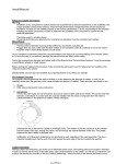
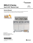
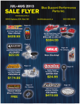
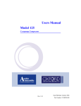
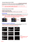
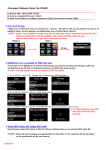
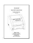
www.wilwood.com
ASSEMBLY INSTRUCTIONS
FOR
W6AR/ST ROAD RACE BIG BRAKE FRONT HAT KIT
WITH 14.00” DIAMETER DYNAMIC MOUNT SV-GT ROTORS
1997 - 2004 CHEVROLET C-5 CORVETTE
2005 - PRESENT CHEVROLET C-6 / Z06
PART NUMBER GROUP
140-10226
DISC BRAKES SHOULD ONLY BE INSTALLED BY SOMEONE
EXPERIENCED AND COMPETENT IN THE INSTALLATION AND
MAINTENANCE OF DISC BRAKES
READ ALL WARNINGS
WARNING
IT IS THE RESPONSIBILITY OF THE PERSON INSTALLING ANY BRAKE COMPONENT OR KIT TO DETERMINE THE SUITABILITY OF THE
COMPONENT OR KIT FOR THAT PARTICULAR APPLICATION. IF YOU ARE NOT SURE HOW TO SAFELY USE THIS BRAKE COMPONENT OR
KIT, YOU SHOULD NOT INSTALL OR USE IT. DO NOT ASSUME ANYTHING. IMPROPERLY INSTALLED OR MAINTAINED BRAKES ARE
DANGEROUS. IF YOU ARE NOT SURE, GET HELP OR RETURN THE PRODUCT. YOU MAY OBTAIN ADDITIONAL INFORMATION AND
TECHNICAL SUPPORT BY CALLING WILWOOD AT (805) 388-1188, OR VISIT OUR WEB SITE AT WWW.WILWOOD.COM. USE OF WILWOOD
TECHNICAL SUPPORT DOES NOT GUARANTEE PROPER INSTALLATION. YOU, OR THE PERSON WHO DOES THE INSTALLATION MUST
KNOW HOW TO PROPERLY USE THIS PRODUCT. IT IS NOT POSSIBLE OVER THE PHONE TO UNDERSTAND OR FORESEE ALL THE ISSUES
THAT MIGHT ARISE IN YOUR INSTALLATION.
RACING EQUIPMENT AND BRAKES MUST BE MAINTAINED AND SHOULD BE CHECKED REGULARLY FOR FATIGUE, DAMAGE, AND WEAR.
Need Additional Information?
Use Your SmartPhone and
Jump to Our Technical Tips
Section on Our Web Site.
WARNING
DO NOT OPERATE ANY VEHICLE ON UNTESTED BRAKES!
SEE MINIMUM TEST PROCEDURE WITHIN
ALWAYS UTILIZE SAFETY RESTRAINT SYSTEMS AND ALL OTHER AVAILABLE SAFETY EQUIPMENT WHILE OPERATING THE VEHICLE
IMPORTANT • READ THE DISCLAIMER OF WARRANTY INCLUDED IN THE KIT
NOTE: Some cleaners may stain or remove the finish on brake system components. Test the cleaner on a hidden portion
of the component before general use.
Important Notice - Read This First
Before any tear-down or disassembly begins, review the following information:
• This kit will fit most 18” and larger wheels, please refer to wheel clearance diagram (Figure 2, page 3) for your
specific requirements. For ALL other wheels, consult the wheel clearance diagram (Figure 2, page 3) to
determine compatibility. Parts that have been installed may not be returned or exchanged.
• Front brake kits do not include flex lines. OEM brake lines will not adapt to Wilwood calipers. Check the
assembly instructions, or associated components section for brake line recommendations before assembly.
In addition, Wilwood offers an extensive listing of brake lines and fittings on our web site: www.wilwood.com.
• Due to OEM production differences and other variations from vehicle to vehicle, the fastener hardware and
other components in this kit may not be suitable for a specific application or vehicle.
• It is the responsibility of the purchaser and installer of this kit to verify suitability / fitment of all components
and ensure all fasteners and hardware achieve complete and proper engagement. Improper or inadequate
engagement can lead to component failure.
Photographic Tip
We suggest you take digital photos of the brake system setup before and during the disassembly procedure. This will aid in the event
that something is not compatible with the new brake components and be a valuable tool to assist in the trouble-shooting process.
Exploded Assembly Diagram
9
10
13
ORIGINAL OEM BOLT AND
WASHER REINSTALLED
12
11
14
EXISTING
HUB
ASSEMBLY
2
8
3
1
4
6
5
WARNING
INSTALLATION OF THIS KIT SHOULD ONLY BE
PERFORMED BY PERSONS EXPERIENCED IN
THE INSTALLATION AND PROPER OPERATION
OF DISC BRAKE SYSTEMS.
NOTE
SPECIFIC PARTS MAY VARY FROM DIAGRAM
7
Figure 1. Typical Installation Configuration
Page 2
Parts List
ITEM NO.
1
2
3
4
5
6
7
8
8A
9
10
11
12
13
14
PART NO.
250-11721
240-8969
160-8398/99
170-11740
240-11240
230-6738
300-8429
120-11657/58-RS
120-11657/58-RSN
230-9182
240-11101
230-9080
240-3902
300-10827
15H-9979K
DESCRIPTION
Bracket, Caliper Mounting
Washer, .562 I.D. x 1.121 O.D. x .029 Thick
Rotor, SV-GT 1.25” X 14.00” Dia, 12 x 8.75” Bolt Circle (one each, right and left)
Hat, Dynamic Mount 5 x 4.75, .290 Offset, 12 x 8.75 Bolt Circle
Washer, .265 I.D. x.500 O.D. x .063 Thick
Bolt, 1/4-28 x .75” Long, 12 Point
T-Nut, 1/4-28
Caliper, W6AR/ST (one each, right and left)
Caliper, W6AR/ST, Nickel
Nut, 7/16-20, Self-Locking, 12 Point
Washer, .453 I.D. x .750 O.D. x .063 Thick
Stud, 7/16-14 x 7/16-20 x 3.375 long (pre installed in bracket)
Washer, .441 I.D. x 1.000 O.D. x .016 Thick
Spacer, .453 I.D. x 1.00 O.D. x .300 Long
Pad, PolyMatrix 15H Compound, 6617H, Axle Set
QTY
2
12
2
2
24
24
24
2
2
4
4
4
16
4
1
NOTES: Part Number 230-6656 Rotor Bolt Kit, includes part numbers 230-6738, 240-11240 and 300-8429
Part Number 250-11720 Caliper Mounting Bracket Kit, includes P/N 250-11721, 230-9080, 230-9182, 240-3902, 240-11101, 240-8969 & 300-10827
Item 8A uis an optional item and included in the “-N” nickel caliper kit. Add “-N” to end of part number when ordering
Wilwood offers an optional Braided Stainless Steel Hose Kit. Order part number 220-8176 (C-5) or 220-9100 (C-6) (not included in kit)
General Information and Disassembly Instructions
•Installation of this kit should ONLY be performed by individuals experienced in the
installation and proper operation of disc brake systems. Prior to any attempt to
install this kit, please check the following to ensure a trouble free installation.
3.80 (96,5)
1.57 (39,9)
.20 (5,1)
.50 (12,7)
RADIUS
CALIPER
•Inspect the contents of this kit against the parts list to ensure that all
components and hardware are included.
8.05
(204,5)
•Make sure this is the correct kit to fit the exact make and model year of your axle
and wheels. This kit is designed for direct bolt-on installation to 1997 through
current model year Chevrolet C-5 and C-6 Corvette hubs, but requires minimum of
18” diameter wheels. Check wheel clearance diagram.
•Verify your wheel clearance using Figure 2.
•Verify that the factory hub and stud pattern matches the stud hole pattern in the hats
supplied with this kit. Hubs that have been modified with different size studs or lug
patterns may require modifications to the hat that must be performed by a
qualified machinist.
•WARNING: Brake pads included in this kit are intended for high temperature race
use only. Extended use at low temperature can cause accelerated rotor and pad
wear. Please see the associated components list on the last page of this data sheet
for alternative brake pad compounds for other uses.
Disassembly
•Disassemble the original equipment front brakes: Raise the front wheels off the
ground and support the front suspension according to the vehicle
manufacturer’s instructions.
4.59
(116,6)
CENTER
LINE OF
WHEEL
2.78 (70,6)
CENTER REGISTRATION
WHEEL MOUNT SURFACE
WILWOOD ROTOR
1.25 (31,8) ROTOR THICKNESS
NOTE: A MINIMUM OF .080” CLEARANCE MUST BE MAINTAINED
BETWEEN THE WHEEL AND CALIPER IN ALL AREAS
Figure 2. Wheel Clearance Diagram
•Remove the wheel. Remove the two bolts from the backside of the spindle that hold the stock caliper mounting bracket and lift off the
bracket and stock caliper as one unit. If space is a problem, you may have to unbolt the stock caliper from the caliper bracket before
removal. Save the stock caliper mounting bracket bolts and washers, they will be utilized during reassembly, then slide off the stock
hat and rotor assembly.
•Clean and de-grease the spindles as well as the stock caliper bracket bolts. Inspect and remove all nicks, burrs, rust, or debris from
the hubs that would prevent the rotor hats from sitting squarely on the hub face.
Page 3
Assembly Instructions
Assembly Instructions (numbers in parenthesis refer to the part list/diagram on the preceding page):
•The caliper mount bracket assembly (1) should be installed first with clean, dry threads on the mounting bolts. Install the bracket using
the original caliper mount bolts. The bracket must tighten squarely against the outboard side of the caliper mount bosses on the
spindle body. Inspect for interference from casting irregularities, machining ridges, burrs, etc. Use one thin shim (2) between the
bracket and spindle during initial trial fitting. Later, after the caliper, pad, and rotor alignment has been checked, and any necessary
shims have been put in place, the mount bolts should be coated with red Loctite® 271 and torqued to 65 ft-lbs.
• Assemble the rotor (3) to the hat (4) with the bolts (6), washers (5) and t-nuts (7) as
shown in the configuration pictured in Figure 1. Follow all additional instructions included with
the bolt kit. Using an alternating sequence, apply red Loctite® 271 to the threads and torque
bolts to 120 in-lb. For an added measure of security, the bolts may be safety wired using
standard 0.032 inch diameter stainless steel safety wire as shown in Figure 3. Please refer to
Wilwood’s data sheet DS-386 (available at www.wilwood.com/Pdf/DataSheets/ds386.pdf) for
complete safety wire installation instructions.
• Install the hat and rotor assembly onto the hub. Check to be sure the hat seats squarely
against the hub. The hub must be free from any rust, debris, casting burrs, machining
irregularities, etc. Use three lug nuts to hold the rotor and hat firmly against the hub during the
next phases of the installation and clearance checking procedures.
BEGIN BY SLIDING THE 0.032"
DIAMETER WIRE THROUGH TWO OF
THE HOLES (LEFT) THAT ARE 180°
APART.
TWIST THE WIRE AS
SHOWN (BELOW) USING SAFETY
WIRE PLIERS. NOW SLIDE ONE
WIRE THROUGH TWO OF THE
HOLES (180° APART) AND WRAP THE
OTHER WIRE AROUND THE BOLT.
TWIST THE WIRES TOGETHER TO
FORM A PIGTAIL. SEE DS-386 FOR
COMPLETE DETAILS.
Figure 3. Safety Wire Diagram
• Install one shim (12) and spacer (13) over each stud (11) on the radial mount bracket (1). Slide
the caliper (8) in place over the studs and rotors and install the washer (10) and lock nut (9) to
hold the caliper in place. The caliper bleed screws should be pointing up. Snug the lock nuts
(9) and check that the rotor (3) is centered in the caliper (8). Add or subtract .029" shims (2)
as necessary between the mount bracket and the spindle to center the caliper.
• Remove the two caliper pad retaining pins from the caliper (8) by popping out the pin retaining clips and sliding out the pins. Slide the
brake pads (14) into place. They should install easily without interference. Check that the outside radius of the brake pad is aligned
with the outside diameter radius of the rotor face. Add or subtract shims (12) between the caliper and mount bracket to gain the proper
alignment. Reinstall the pad retaining pins and secure using the pin retaining clips
• Remove the lug nuts that were holding the hat in place. Install the wheel and torque the lug nuts to specification. Check to see that
the wheel rotates freely without interference.
• Once all clearances have been checked, remove the wheel,
caliper, hat, and rotor from the spindle and hub. Secure the caliper
mounting bracket (1) to the spindle using red Loctite® 271.
Torque the bolts to 65 ft-lbs. Reinstall the hat and rotor assembly
and again use several lug nuts to hold it in place. Lubricate caliper
mounting studs and nuts with lightweight oil, reinstall the caliper,
torque the caliper nuts (9) to 47 ft-lbs.
FLEXLINE
BRACKET
FRAME
WILWOOD
W6A CALIPER
Stock Brake Line Disassembly Instructions
•Unbolt banjo bolt from back of caliper.
CLIP
90° ELBOW
HARDLINE
Figure 4. Brake Line Diagram
•Unbolt rubber hose from hard line at frame.
•Pull the clip that holds the rubber hose to the bracket at the frame.
On some models, it will be necessary to re-use these clips to retain
the new hoses.
Installing the New Flexlines
•Purchase flexline hose kit part number 220-8176 for all 1997-2004 (C-5), or part number 220-9100 for all 2005-present (C-6). Be sure
to follow any additional instructions provided with the line kit. These line kits are not included with the brake it.
Page 4
Assembly Instructions (Continued)
•Specified brake hose kits are based on production based vehicles. They may not work with all models or custom built vehicles using
production Corvette suspension components. It is the installer's responsibility to ensure that all fittings and hoses are the correct size
and length, to ensure proper sealing and that they will not be subject to crimping, strain and abrasion from vibration or interference with
suspension components, brake rotors, or wheels. Carefully route the lines to prevent contact with these or any other elements
that could cause damage to the lines.
•In absence of specific instructions for brake line routing, the installer must use his best professional judgment on correct routing and
retention of lines to ensure safe operation. Test vehicle brake system per the 'minimum test' procedure stated within this document
before driving. After road testing, inspect for leaks and interference. Initially after install and testing, perform frequent checks of the
vehicle brake system and lines before driving. Confirm that there is no undue wear or interference between the lines and any element
of the chassis or suspension. Afterwards, perform periodic inspections for function, leaks and wear in a interval relative to the usage
of vehicle.
Bleed the Brake System
•First, reference the manufacturer’s service manual for the proper flushing and bleeding procedures for your vehicle, and then consult
the additional information and recommendations below for proper bleeding instructions.
•Fill and bleed the system with Wilwood EXP 600 Plus Racing Brake Fluid from a new bottle. Used fluid must be completely flushed
from the system to prevent contamination.
•NOTE: Silicone DOT 5 brake fluid is NOT recommended for racing or performance driving.
•To properly bleed the brake system, begin with the caliper farthest from the master cylinder. Bleed the outboard bleed screw first, then
the inboard. Repeat the procedure until all calipers in the system are bled, ending with the caliper closest to the master cylinder.
•NOTE: When installing a new master cylinder, it is important to bench bleed the master cylinder first.
•Test the brake pedal.
It should be firm, not spongy and stop at least 1 inch from the floor under heavy load. If the brake pedal is spongy, bleed the system
again.
If the brake pedal is initially firm, but then sinks to the floor, check the system for fluid leaks. Correct the leaks found and then bleed
the system again. Do not attempt to test or drive the car until a firm pedal has been established.
Finishing the Installation
•NOTE: With the installation of after market disc brakes, the wheel track and/or wheel clearance may change depending on the
application. Check your wheel offsets and clearances before final assembly. Do not operate any vehicle if there is interference between
any part of the wheel, brake caliper, or suspension component.
•Remove the lug nuts that were holding the hat in place. Install the wheel and torque the lug nuts to specification.
•Repeat this entire procedure for the other wheel.
•If after following the instructions, you still have difficulty in assembling or bleeding your Wilwood disc brakes, consult your local chassis
builder, or retailer where the kit was purchased for further assistance.
Page 5
Brake Testing
WARNING • DO NOT DRIVE ON UNTESTED BRAKES
BRAKES MUST BE TESTED AFTER INSTALLATION OR MAINTENANCE
MINIMUM TEST PROCEDURE
• Make sure pedal is firm: Hold firm pressure on pedal for several minutes, it should remain in position without
sinking. If pedal sinks toward floor, check system for fluid leaks. DO NOT drive vehicle if pedal does not stay firm
or can be pushed to the floor with normal pressure.
• At very low speed (2-5 mph) apply brakes hard several times while turning steering from full left to full right, repeat
several times. Remove the wheels and check that components are not touching, rubbing, or leaking.
• Carefully examine all brake components, brake lines, and fittings for leaks and interference.
• Make sure there is no interference with wheels or suspension components.
• Drive vehicle at low speed (15-20 mph) making moderate and hard stops. Brakes should feel normal and
positive. Again check for leaks and interference.
• Always test vehicle in a safe place where there is no danger to (or from) other people or vehicles.
• Always wear seat belts and make use of all safety equipment.
Pad and Rotor Bedding
BEDDING STEPS FOR NEW PADS AND ROTORS – ALL COMPOUNDS
Once the brake system has been tested and determined safe to operate the vehicle, follow these steps for the bedding of all new pad
materials and rotors. These procedures should only be performed on a race track, or other safe location where you can safely and
legally obtains speeds up to 65 MPH, while also being able to rapidly decelerate.
• Begin with a series of light decelerations to gradually build some heat in the brakes. Use an on-and-off the pedal technique by
applying the brakes for 3-5 seconds, and then allow them to fully release for a period roughly twice as long as the deceleration cycle.
If you use a 5 count during the deceleration interval, use a 10 count during the release to allow the heat to sink into the pads and
rotors.
• After several cycles of light stops to begin warming the brakes, proceed with a series of medium to firm deceleration stops to
continue raising the temperature level in the brakes.
• Finish the bedding cycle with a series of 8-10 hard decelerations from 55-65 MPH down to 25 MPH while allowing a proportionate
release and heat-sinking interval between each stop. The pads should now be providing positive and consistent response.
• If any amount of brake fade is observed during the bed-in cycle, immediately begin the cool down cycle.
• Drive at a moderate cruising speed, with the least amount of brake contact possible, until most of the heat has dissipated from the
brakes. Avoid sitting stopped with the brake pedal depressed to hold the car in place during this time. Park the vehicle and allow the
brakes to cool to ambient air temperature.
COMPETITION VEHICLES
• If your race car is equipped with brake cooling ducts, blocking them will allow the pads and rotors to warm up quicker and speed up
the bedding process.
• Temperature indicating paint on the rotor and pad edges can provide valuable data regarding observed temperatures during the
bedding process and subsequent on-track sessions. This information can be highly beneficial when evaluating pad compounds and
cooling efficiencies.
Page 6
Pad and Rotor Bedding (Continued)
POST-BEDDING INSPECTION – ALL VEHICLES
• After the bedding cycle, the rotors should exhibit a uniformly burnished finish across the entire contact face. Any surface irregularities
that appear as smearing or splotching on the rotor faces can be an indication that the brakes were brought up to temperature too
quickly during the bedding cycle. If the smear doesn’t blend away after the next run-in cycle, or if chatter under braking results,
sanding or resurfacing the rotors will be required to restore a uniform surface for pad contact.
PRE-RACE WARM UP
• Always make every effort to get heat into the brakes prior to each event. Use an on-and-off the pedal practice to warm the brakes
during the trip to the staging zone, during parade laps before the flag drops, and every other opportunity in an effort to build heat in
the pads and rotors. This will help to ensure best consistency, performance, and durability from your brakes.
DYNO BEDDED COMPETITION PADS AND ROTORS
• Getting track time for a proper pad and rotor bedding session can be difficult. Wilwood offers factory dyno-bedded pads and rotors
on many of our popular competition pads and Spec 37 GT series rotors. Dyno-bedded parts are ready to race on their first warm
up cycle. This can save valuable time and effort when on-track time is either too valuable or not available at all, Dyno-bedding
assures that your pads and rotors have been properly run-in and are ready to go. Contact your dealer or the factory for more
information on Wilwood Dyno-Bedding services.
NOTE:
NEVER allow the contact surfaces of the pads or rotors to be contaminated with brake fluid. Always use a catch bottle with a hose to
prevent fluid spill during all brake bleeding procedures.
Connect with Wilwood
Wilwood Social Forum
Wilwood Facebook
Wilwood Twitter
Wilwood YouTube
Associated Components
PART NO.
290-6209
220-8176
220-9100
15A-9977K
15B-9978K
150-9980K
130-5972
180-9874
220-6069
300-5876
140-10638
DESCRIPTION
Wilwood Racing Brake Fluid (EXP 600 Plus) (16.9 oz)
Flexline Kit, 1997-2004 Chevrolet Corvette, C-5
Flexline Kit, 2005 - Present Chevrolet Corvette, C-6 / Z06
Axle Pad Set, PolyMatrix A, 6617A
Axle Pad Set, PolyMatrix B, 6617B
Axle Pad Set, BP-30 Smart Pad, 6617-30
Caliper O-Ring Kit
Pad Retainer Pin Set
Caliper Bleed Screw Set
Caliper Bridge SRS Wear Plate
BNSL4R Road Race Rear Brake Kit, 12.88” GT-48 Discs, All C5 & C6
Wilwood Disc Brakes • 4700 Calle Bolero, Camarillo, CA 93012
Phone 805 / 388-1188 • Fax 805 / 388-4938
www.wilwood.com • E-mail Technical Assistance: [email protected]
DS-592M REV DATE: 05-30-13