1
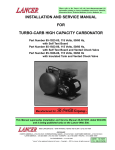
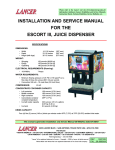
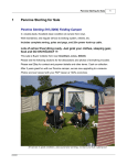
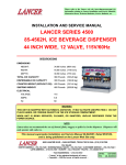
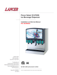
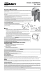
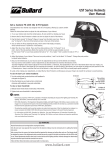
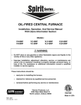
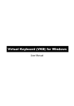
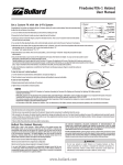
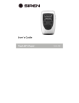
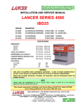
Please refer to the Lancer web site (www.lancercorp.com) for
information relating to Lancer Installation and Service Manuals,
Instruction Sheets, Technical Bulletins, Service Bulletins, etc.
INSTALLATION AND SERVICE MANUAL
FOR
TWO LITER PREMIX
PUSH CART
(Part Number 85-1751)
This manual is an initial release
6655 LANCER BLVD. • SAN ANTONIO, TEXAS 78219 USA • (210) 310-7000
FAX SALES
• NORTH AMERICA – 210-310-7245 • INTERNATIONAL SALES – 210-310-7242 • CUSTOMER SERVICE – 210-310-7242 •
• LATIN AMERICA – 210-524-9567 / 210-310-7245 • EUROPE – 32-2-755-2399 • PACIFIC – 61-8-8268-1978 •
FAX ENGINEERING: • 210-310-7096
"Lancer" is the registered trademark of Lancer • Copyright — 1997 by Lancer, all rights reserved.
DATE:
P.N.
01/27/97
28–0325
TABLE OF CONTENTS
TABLE OF CONTENTS ......................................................................................................................................i
SPECIFICATIONS...............................................................................................................................................i
1. PACKAGING AND INSPECTION................................................................................................................1
1.1 RECEIVING AND UNPACKING .........................................................................................................1
1.2 COMPONENTS..................................................................................................................................1
2. ASSEMBLY..................................................................................................................................................1
2.1 ASSEMBLY INSTRUCTIONS ............................................................................................................1
2.2 CO2 REGULATOR ASSEMBLY .........................................................................................................3
2.3 CUTTING THE BOTTLE TUBES .......................................................................................................3
3. OPERATION ................................................................................................................................................4
3.1 CUP DISPENSER ..............................................................................................................................4
3.2 DISPENSING VALVE .........................................................................................................................4
3.3 CO2 PRESSURE ASSEMBLY............................................................................................................4
3.4 CO2 PRODUCT BOTTLES AND CO2 CYLINDER EXCHANGE .......................................................4
3.5 CO2 CYLINDER REFILL PROCEDURE ............................................................................................5
3.6 UNLOADING 2 LITER PET BOTTLES FROM PUSH CART ICE CUBE COOLER ..........................5
4. MAINTENANCE...........................................................................................................................................7
4.1 CUP DISPENSER ..............................................................................................................................7
4.2 CLEANING AND SANITIZING ...........................................................................................................7
4.3 REPLACEMENT OF BEVERAGE HOSE INSIDE DISPENSING VALVE ASSEMBLY......................7
4.4 CO2 CYLINDER .................................................................................................................................7
4.5 CO2 REGULATOR ASSEMBLY .........................................................................................................8
5. ILLUSTRATIONS, PARTS LISTINGS, AND WIRING DIAGRAMS ..........................................................10
5.1 COOLER AND HARDWARE .......................................................................................................10-11
5.2 CO2 CYLINDER ASSEMBLY ...........................................................................................................11
5.3 REGULATOR ASSEMBLY ...............................................................................................................12
5.4 CONNECTOR VALVE ASSEMBLY ..................................................................................................12
5.5 DISPENSING VALVE ASSEMBLY ...................................................................................................13
5.6 CUP DISPENSER ASSEMBLY ........................................................................................................13
5.7 REFILL ADAPTER ASSEMBLY .......................................................................................................14
5.8 PRESSURE GAUGE TESTING ASSEMBLY ...................................................................................14
SPECIFICATIONS
CARBON DIOXIDE (CO2) REQUIREMENTS
Pressure Regulator Setting
Relief Valve Setting
CO2 Cylinder Capacity
CO2 Cylinder Refill
22 PSI (Preset)
30 PSI (Preset)
10 ounces of liquid CO2 (Sufficient for 5 complete
discharges of each dispensing system)
Use 50 pound CO2 Bottle with a dip tube
DRINK CAPACITY
The system consists of two (2) independent banks of five (5) two (2) liter bottles. Each bank is capable of
providing 34 - 12 ounce cups or 24 - 16 ounce cups per one complete discharge using no ice in cup.
i
1. PACKAGING AND INSPECTION
1.1
RECEIVING AND UNPACKING
Open shipping case and carefully remove beverage dispenser components. Each unit has been
thoroughly inspected and tested prior to shipment. Inspect all items for damage. In the event of
shortage or damage, notify the delivering carrier (as well as Lancer) immediately. Merchandise
should be inspected for concealed damage no later than 15 days after receipt.
1.2
COMPONENTS
A.
B.
C.
D.
E.
Installation and Service Manual
CO2 Cylinders
Dispensing Valve Assemblies - two (2)
CO2 Regulator Assemblies - two (2)
Eight (8) Bottle Connector/Valve
Assemblies
F. Cup Dispenser
G. Graphics Panel (Optional)
H. Refill Adapter (Optional)
I. Pressure Gauge Assembly (Optional)
2. ASSEMBLY
2.1
ASSEMBLY INSTRUCTIONS
A. Unpack the push cart and check the
items received against the parts list.
B. Assemble the push cart per the
Instruction Sheet included with cart.
NOTE
The riser is supplied mounted to the
Push Cart.
C. Install the cup rest bracket on the push
cart riser.
Fully Assembled Push Cart
Side View
Figure 1
NOTE
The cup rest bracket sits on the riser,
with the angle flange of the bracket
inside the riser, the cube resting on the
bracket to hold it down.
D. Unpack the cup dispenser, and install
the two mounting brackets on the push
cart handle. The smaller tapered end of
the bracket should be facing down.
E. Unpack the cube, being careful to not
damage the dispensing valves while
unpacking. Place the cube on the riser,
and on the angle flange of the cup dispenser.
F. Place the drip tray in the cup rest
bracket. Place the wire cup rest in the
drip tray.
G. Place the cup dispenser on the two
mounting brackets. The black end of
the cup dispenser is up (i.e., the cups
are displaced up). Place cups in the cup
dispenser.
1
Fully Assembled Push Cart
Backside View
Figure 2
H. Place the trash bin on the front of the
cart as shown.
I. Install the (optional) umbrella in the
mounting bracket.
J. Remove the caps of eight (8) 2 liter
beverage products. Screw on the
eight connector valve bottle fitting
assemblies.
SPRINGS
ATTACH VALVES TO
THESE LOCATIONS
CAUTION
DO NOT OVER TIGHTEN THE FITTINGS.
OVER TIGHTENING CAN CAUSE
LEAKS! PLACE THESE BOTTLES IN
THE SPRING FRAME AS SHOWN.
SPRINGS
Bottle Hold Down Springs and
Bottle Placement
K. Remove the caps of two (2) 2 liter
products. Screw the bottle onto the
Figure 3
connector valve bottle fittings inside
the cube that are connected to the dispensing valves. Place these two bottles in the spring
frame farthest away from the valves (see Figure 3).
NOTE
Place the four (4) corner bottles in first. Then put the bottles in between them. Then put the
four (4) center bottles in.
L. Reverse this order to remove the bottles.
M. Charge the two CO2 cylinders following the instructions on the cylinders.
CAUTION
BE SURE TO WEIGH THE CYLINDERS AFTER CHARGING. THE FILLED WEIGHT MUST NOT
EXCEED 1.0 KG, OR 2 LB., 3 OZ. FAILURE TO KEEP THE WEIGHT BELOW THIS AMOUNT
COULD RESULT IN OVERPRESSURE OF THE CYLINDER, AND CAUSE THE SAFETY RELIEF
VALVE TO OPEN.
IN
QUICK DISCONNECT CYLINDER COUPLING
PR E S E T
TO 2 2 P SI
WARNING
CONTENTS UNDER
PRESSURE
HANDLE WITH CARE
RESET
TO 22 PSI
PR E S E T
TO 2 2 P SI
NOTE:
MAXIMUM CYLINDER WEIGHT
FULL, SHOULD NOT EXCEED
2 LB. 3 OZ.(1.0 KG.)
LANCER PN 06-1213
REGULATOR
ASSEMBLY
T
OU
RESET
TO 22 PSI
CO2 FILLING INSTRUCTIONS
WARNING
CONTENTS UNDER
PRESSURE
HANDLE WITH CARE
NOTE:
MAXIMUM CYLINDER WEIGHT
FULL, SHOULD NOT EXCEED
2 LB. 3 OZ.(1.0 KG.)
LANCER PN 06-1213
NOTE: CO2 BOTTLE MUST HAVE A DIP TUBE,
OR IT MUST BE INVERTED, TO INSURE
FILLING THE SMALL CO2 CYLINDER
WITH LIQUID.
TO FILL:
CO2 CYLINDER
CO2 BOTTLE
CO2 BOTTLE VALVE
FILL ADAPTER
VENT VALVE
CO2 CYLINDER VALVE
FILL
ADAPTER
WARNING
CONTENTS UNDER
PRESSURE
HANDLE WITH
CARE
NOTE:
MAXIMUM CYLINDER
FULL SHOULD
NOT
2 LB. 3 OZ.
(1.0 KG.)
TO FILL:
1) CLOSE THE
THE REFI
2) CONNECT
TO THE
3) OPEN
CO
4) OPEN
VALVE
WITH
THE
5) OPE
THE
CO
CLO
6) OP
BOT
GA
7) CLO
CO 2
8) CLO
CO 2
9) OP
THE
10) DIS
CYL
AD
11) WE
THE
BE 2
IF IT
THE
AND
SPEC
CO 2 BOTTLE
WITH DIP TUBE
Quick Disconnect Cylinder Coupling
2
CO2 CYLINDER
ASSEMBLY
N. Place the two cylinders in the spring
frame as shown. Connect a regulator
assembly to each of the cylinder
assemblies, by pulling back on the
quick disconnect body on the regulator,
and pushing it on the stem on the
cylinder assembly.
O. Connect the regulator assembly and
the bottles in series as follows: Plug
the hose end of the regulator assembly
into the fitting on the bottle fitting
assembly, on the center bottle farthest
away from the CO2 cylinder. Plug the
hose end from that bottle into the
corner bottle next to the dispensing
valves. Plug the hose end from that
bottle into the center bottle along the
side. Plug the hose end from that
bottle into the center bottle next to the
CO2 cylinder. Plug the hose end from
that bottle into the bottle with the hose
that connects to the valves. Make sure
the dispensing valves are closed.
P. Open the CO2 cylinder valve. Check
for leaks.
Q. Make sure the drain plug is in the drain
hole in the bottom of the cube. Cover
with ice as required.
45
o
MEASUREMENT
DISTANCE
Cutting the Bottle Tube
Figure 5
NOTE
Do not allow water to rise above the
spring frame.
2.2
CO2 REGULATOR ASSEMBLY
A. Attach CO2 Regulator Assembly to CO2
Cylinder, utilizing Quick Disconnect
Cylinder Coupling (see Figure 4).
B. Pull back Socket Sleeve to connect or
disconnect coupling.
CONNECTOR VALVE
ASSEMBLY
NOTE
Do not attempt to disconnect cylinder
coupling while under pressure.
Coupling will not disconnect.
2.3
CUTTING THE BOTTLE TUBES
Cutting the bottle tubes to the correct
length is an important step. Bottle tubes
are supplied as loose items, to be cut by
the user to the correct length for the height
of the bottles being used. Use the following
procedure when cutting the bottle tubes
(see Figure 5):
PREMIX BOTTLE
(CUSTOMER SUPPLIED)
A. Measure from the very bottom of an
empty bottle, to the top of the bottle.
Connector Valve Assembly
Figure 6
3
B.
C.
D.
E.
Cut the tubes 7/8 inch (22 mm) shorter than the height measured just above.
If the end of the tube is not already cut at an angle, carefully cut the tube at a 45° angle.
Push the tube onto the barbed end of the connector/valve bottle fitting assembly.
Slowly open the valve on the CO2 cylinder. Check for leaks. Close the lid of the cooler.
3. OPERATION
3.1
CUP DISPENSER
The Cup Dispenser will hold cup sizes ranging between 12 and 20 ounces in capacity.
3.2
DISPENSING VALVE
The Dispensing Valve will dispense any type of beverage product. Beverage flow is controlled by
turning the Flow Screw on the Valve Body until desired flow is maintained (see Figure 8). The
Product Hose is insulated to maintain constant product temperature regardless of
environmental conditions. The Valve operates by pulling the handle forward, and upon release, the
Valve will automatically close.
3.3
CO2 PRESSURE ASSEMBLY
All beverage products are dispensed utilizing CO2 pressure. Each CO2 Cylinder has a rated
capacity of ten (10) ounces of liquid CO2 gas, which is sufficient to dispense five (5) complete refills
of any type beverage product. The empty CO2 Cylinder is then exchanged for a charged CO2
Cylinder. CO2 Cylinders may be refilled by the user through a fast, safe, and inexpensive method
described in this manual, or CO2 Cylinders may be refilled by a local commercial liquid gas
supplier. It is advisable to maintain a supply of charged CO2 Cylinders for quick exchange. The
CO2 Cylinder is ICC approved and equipped with a Safety Diaphragm Relief Valve.
A. Pressure Regulator setting
The Regulator pressure is preset to 22 PSI.
B. Safety Relief Valve setting
The Safety Relief Valve is preset to 30 PSI.
C. To disconnect CO2 cylinder from regulator assembly
Follow the procedure below:
(1) Close the Cylinder Valve.
(2) Bleed off pressure through a Gas Socket.
(3) Disconnect Cylinder, by pulling back sleeve on Cylinder Coupling.
3.4
CO2 PRODUCT BOTTLES AND CO2 CYLINDER EXCHANGE
Empty beverage bottles and an empty CO2 Cylinder (when necessary) can be exchanged in about
30 seconds, upon the Vendor’s return to the refill station.
NOTE
The 2 liter push cart contains two independent dispenser systems. The total number of servings per
cart is therefore 2X the numbers shown the chart in Figure 7.
A. Open lid of ice cube cooler.
B. Disconnect the lines to the connector valve assembly on each bottle.
C. Remove the bottle with the hose to the dispensing valve. Unscrew the Connector/Valve
Assembly from that bottle.
D. Follow steps (1) through (6) below, if the CO2 Cylinder is to be exchanged.
(1)
(2)
(3)
(4)
Remove CO2 Cylinder Assembly.
Close Cylinder Valve.
Bleed off pressure through Gas Socket.
Disconnect empty Cylinder from Regulator Assembly (normally, the Cylinder is not
4
NUMBER OF SERVINGS BY SIZE OF INDIVIDUAL SERVING
NUMBER OF
SERVINGS PER
COMPLETE REFILL
ACTUAL PRODUCT
SERVED IN OUNCES
12
34
16
24
Figure 7
completely empty, but do not bleed off as the small remaining amount is later used to
facilitate refill).
(5) Connect full (charged) Cylinder to Regulator Assembly.
(6) Open Cylinder Valve and replace CO2 Assembly.
E.
F.
G.
H.
3.5
Remove empty product bottles and replace with full 2-liter bottles of Premix.
Connect Dispensing Valve Assembly to a bottle, and place into the unit or cooler.
Connect CO2 Assembly to bottle. Connect all lines to all bottles (see Figure 7). Close cover.
Refill Cup Dispenser.
CO2 CYLINDER REFILL PROCEDURE
A. CO2 Cylinder Assembly (PN 20-0016). CO2 Cylinders may be refilled, following the outlined
procedures below, at the rate of one (1) CO2 Cylinder per minute. The following equipment is
necessary to utilize the refill method:
NOTE
The fill adapter (PN 17-0385/01) is designed to be placed on USA CO2 bottles with 0.830-14
NGO thread. If the threads are different on the CO2 bottles being used, it will be necessary to
make an adapter to interface between the CO2 bottle being used and the adapter. An adapter
is not supplied because of thread variances between bottles. It will be necessary to make an
identical piece, with the threads on the female end identical to the threads on the CO2 bottle
being used.
(1) Fifty (50) pound CO2 supply bottle with a siphon (dip) tube. This should be available from
any local commercial liquid gas supplier. A fifty (50) pound liquid CO2 bottle will normally
refill approximately seventy to seventy-two (70 to 72) CO2 Cylinders.
(2) CO2 Cylinder Refill Adapter (PN 17-0385/01).
(3) Scale with minimum graduations of a quarter ounce (1/4 ounce). Although an accurate
spring scale is acceptable, a triple beam balance scale is preferable. Either scale may be
obtained at a nominal cost from local suppliers.
B. Refill Procedure (see Figure 8)
(1) Connect Refill Adapter to liquid CO2 supply bottle (50 pounds).
(2) Connect empty CO2 Cylinder to Refill Adapter, utilizing Quick Disconnect Coupling. Close
Refill Adapter Vent Valve.
(3) Open CO2 Cylinder valve
(PN 20-0016).
(4) Open supply bottle valve for about three to five (3 to 5) seconds. Close valve.
(5) Open Refill Adapter Vent Valve, allowing pressure to disperse. This chills the CO2 Cylinder.
Close Refill Adapter Vent Valve.
(6) Open supply bottle valve until CO2 Cylinder is filled (hissing sound will stop). Close supply
bottle valve.
5
(7) Close CO2 Cylinder valve.
(8) Open Refill Adapter Vent Valve. This
disperses pressure. Disconnect CO2
Cylinder from Refill Adapter.
NOTE
CO2 FILLING INSTRUCTIONS
NOTE: CO2 BOTTLE MUST HAVE A DIP TUBE,
OR IT MUST BE INVERTED, TO INSURE
FILLING THE SMALL CO2 CYLINDER
WITH LIQUID.
CO2 Cylinder will not disconnect from
Refill Adapter unless Refill Adapter
Vent Valve has been opened.
TO FILL:
(1) CLOSE THE FILL ADAPTOR VENT.
CO2 CYLINDER
CO 2 BOTTLE
CO2 BOTTLE VALVE
FILL ADAPTER
VENT VALVE
CAUTION
CO2 CYLINDER VALVE
DO NOT OPERATE CO2 CYLINDER
WHEN GROSS WEIGHT IS IN EXCESS
OF THAT INDICATED ON THE CO2
CYLINDER. THE CO2 CYLINDER IS
ICC APPROVED AND EQUIPPED WITH
A SAFETY DIAPHRAGM RELIEF
VALVE. IF OPERATED OR STORED
WHEN THE WEIGHT IS IN EXCESS OF
THAT RECOMMENDED, SEVERE
HEAT MAY CAUSE THE SAFETY
DIAPHRAGM RELIEF VALVE TO OPEN;
THEREBY, DISPERSING EXCESSIVE
PRESSURE.
REFER
TO
MAINTENANCE SECTION, AND PARTS
AND SERVICE SECTION, FOR
INSTRUCTIONS ON REPLACING
DIAPHRAGM.
FILL
ADAPTER
(2) CONNECT THE SMALL CO 2
CYLINDER TO THE FILL ADAPTER.
(3) OPEN THE VALVE ON THE SMALL
CO2 CYLINDER VALVE.
(4) OPEN THE CO2 BOTTLE VALVE
FOR 5 SECONDS. CLOSE THE
VALVE.
(5) OPEN THE FILL ADAPTER VENT
VALVE (THIS COOLS THE CO 2
CYLINDER). CLOSE THE VENT
VALVE.
(6) OPEN THE CO2 BOTTLE VALVE
(LISTEN FOR THE GAS FLOW TO
STOP).
(7) CLOSE THE CO2 CYLINDER VALVE.
(8) CLOSE THE CO2 BOTTLE VALVE.
(9) OPEN THE FILL ADAPTER VENT
VALVE.
WARNING
CONTENTS UNDER
PRESSURE
HANDLE WITH
CARE
NOTE:
MAXIMUM CYLINDER
FULL SHOULD
NOT
2 LB. 3 OZ.
(1.0 KG.)
(10) DISCONNECT THE CO2 CYLINDER
FROM THE FILL ADAPTER.
TO FILL:
1) CLOSE THE
THE REFI
2) CONNECT
TO THE
3) OPEN
CO
4) OPEN
VALVE
WITH
THE
5) OPE
THE
CO
CLO
6) OP
BOT
GA
7) CLO
CO 2
8) CLO
CO 2
9) OP
THE
10) DIS
CYL
AD
11) WE
THE
BE 2
IF IT
THE
AND
SPEC
(11) WEIGH THE CO2 CYLINDER. THE
MAXIMUM WEIGHT ALLOWABLE IS
1.0 KG (2 LB., 3 OZ.). IF THE
CYLINDER IS OVERWEIGHT, OPEN
THE VALVE TO EXHAUST GAS.
RE-WEIGH THE CYLINDER.
CO 2 BOTTLE
WITH DIP TUBE
REPEAT AS REQUIRED TO REACH
SPECIFIED WEIGHT.
CO2 Filling Instructions
Figure 8
(9) Weigh CO2 Cylinder. If gross weight is over that indicated on the CO2 Cylinder, bleed off
pressure until referenced weight is achieved. The CO2 Cylinder now contains ten (10)
ounces of liquid CO2 which is sufficient to dispense five (5) complete refills of any type
beverage.
3.6
UNLOADING 2 LITER PET BOTTLES FROM PUSH CART ICE CUBE COOLER
A. Release the quick disconnects from the bottle fittings.
B. Remove the empty bottles from the cube.
WARNING
UNVENTED BOTTLES CAN BECOME PROJECTILES.
CAUTION
VENTING OF THE BOTTLE MUST OCCUR IMMEDIATELY WHEN THE FITTING IS TURNED 1/8
OF A TURN. IF VENTING DOES NOT TAKE PLACE, DEPRESS THE END OF THE QUICK DISCONNECT TO VENT.
C. Remove the bottle fitting from the bottles.
4. MAINTENANCE
4.1
COOLER AND LID
A. Scuff and dirt marks are readily and easily removed with a damp cloth and mild detergent,
although stubborn marks may require a cleaner. At the end of each day’s activity, the unit should
be cleaned and allowed to air dry prior to storage.
B. To drain the cube, pull out the plug in the bottom of the cube. The water will drain out of the
bottom, through the riser, and through a pipe in the center of the riser. If the cube is removed
and tipped to dump the ice, be careful to not damage the dispensing valves.
6
4.2
CUP DISPENSER
A. The Cup Dispenser should be cleaned periodically with a damp cloth and detergent, or cleaner.
The Cup Dispenser is constructed of Stainless Steel which helps to ensure a rust and corrosion
free operation.
B. See Section 5 for parts breakdown and related information.
4.3
CLEANING AND SANITIZING
A. Bottles are to be discarded after each use. However, five (5) empty 2-liter bottles must be
retained for cleaning and sanitizing the unit.
B. Prepare a sanitizing solution of between 50 to 150 PPM of available chlorine, not to exceed 200
PPM and fill one (1) bottle with sanitizing solution.
C. Assemble four (4) empty product bottles into the hold down frame. Place the remaining
product bottle (filled with sanitizing solution in Step B above) into the frame and connect to the
CO2 Cylinder/Regulator Assembly.
D. Connect the CO2 cylinder/pressure regulator to the bottle with sanitizing solution.
E. Connect the four (4) empty, de-pressurized bottles in series, downstream of the sanitizer bottle.
F. Turn on the valve on the CO2 cylinder.
G. Activate the dispensing valve until all the sanitizing solution has been dispensed through the
system.
H. Shut off the CO2.
I. Depressurize by opening the dispensing valve until all pressure is exhausted.
J. Unscrew the connector/valve assembly from each bottle. Drain all sanitizing solution from each
assembly. Drain the cube by pulling the plug in the bottom of the cube.
NOTE
If necessary, push the end of the male fitting of the connector/valve assembly to allow the liquid
solution to drain from the hoses of the connector/valve assembly. Also drain the dispensing
valve hose assembly.
J. Rinse the exterior of all bottle fittings with the sanitizing solution.
K. Air dry in a clean environment. Cover if necessary.
4.4
CO2 CYLINDER
CAUTION
FOR THE FOLLOWING PROCEDURE, DO NOT HOLD THE CO2 CYLINDER WITH A JAW TYPE
WRENCH, OR A VISE. A JAW TYPE WRENCH WILL MAR THE CYLINDER, WEAKEN THE
CYLINDER WALL, AND POSSIBLY CAUSE A FAILURE. CLAMPING THE CO2 CYLINDER IN A
VISE WILL CRUSH THE CYLINDER, AGAIN WEAKENING THE CYLINDER WALL, AND WILL
RESULT IN CYLINDER FAILURE.
HOLD THE CO2 CYLINDER WITH A STRAP WRENCH. THE STRAP WRENCH WILL HAVE A
LEATHER OR CLOTH TYPE STRAP, THAT WILL NOT MAR THE CYLINDER SURFACE.
The CO2 Cylinder used by the cart is virtually free of maintenance. If any maintenance is required,
other than that described below, return the CO2 Cylinder to Lancer for repair.
A. Safety Diaphragm Relief Valve
If the Safety Diaphragm Relief Valve leaks, or the Diaphragm has ruptured due to extreme pressure, follow the instructions provided below. For a parts breakdown, see Section 5.
The safety relief valve is not replaceable. In the event this valve ruptures or leaks, replace the
complete valve (PN 17-0514) as follows:
(1) Open Cylinder Valve and exhaust all CO2 pressure.
(2) Remove adapter from the CO2 valve.
7
(3) Remove the CO2 valve.
NOTE
Hold the CO2 cylinder with a strap wrench as noted above.
(4) Install new CO2 valve. Torque to 20.0 ft lbs.
(5) Install adapter. Torque to 20.0 ft lbs.
(6) Charge the CO2 cylinder. Check for leaks.
B. Repairing Leaks on the CO2 Cylinder Assembly
If a leak should occur because of a failed O-Ring, replace the defective O-Ring:
(1) Between the cylinder and the CO2 valve.
a. Open the CO2 cylinder valve to exhaust all of the CO2 pressure.
b. Remove the CO2 valve from the cylinder.
NOTE
Hold the CO2 cylinder with a strap wrench as noted above.
c. Replace the O-Ring (PN 02-0219) on the valve.
d. Lubricate the O-Ring slightly with a silicone spray.
e. Install the valve on the cylinder. Torque to 20.0 ft lbs.
(2) Between the CO2 valve and the adapter.
a.
b.
c.
d.
Open the CO2 cylinder valve to exhaust all of the CO2 pressure.
While holding the CO2 valve with a wrench, remove the adapter.
Replace the O-Ring (PN 02-0003).
Install the adapter on the valve. Torque to 20.0 ft lbs.
(3) For any other leaks, return the CO2 cylinder assembly to Lancer.
4.5
CO2 REGULATOR ASSEMBLY
For Parts breakdown and related information, see Section 5.
A. Hose Connector
If leakage occurs in the Hose Connector, replace the Hose Connector and hose.
B. CO2 Cylinder Coupling (Socket)
If leakage occurs between the Socket and the Plug, when the CO2 Regulator assembly is
coupled with the CO2 Cylinder, disconnect and visually inspect the Socket O-Ring. If the O-Ring
is nicked, cut, or otherwise defective, replace the O-Ring.
C. CO2 Regulator
CO2 Regulators cannot be disassembled for maintenance without special equipment and
should be returned to Lancer for any needed repair. The following procedure can be used
to check the regulator pressure.
(1) A pressure gauge testing assembly (PN 82-1751) is available to check the relief
valve/regulator pressure (see Section 5.8).
(2) If it is necessary to check or readjust the pressure, follow these steps:
NOTE
The pressure testing assembly is to be used to check the pressure of the regulator
assembly only if the pressure from the regulator assembly (PN 18-0274) is not correct.
(a) Plug the pressure testing assembly onto the male fitting of the regulator assembly.
(b) On the CO2 cylinder, turn on the valve. The pressure of the regulator should be 22 PSI.
8
(3)
(4)
(5)
(6)
(7)
(8)
(9)
IN
(c) If necessary, readjust the regulator to the
correct pressure, by loosening the
locknut, adjusting the screw to the
correct pressure, then tighten the
locknut.
Plug the gauge assembly onto the regulator
assembly (see Figure 9).
Connect the regulator assembly to a CO2
cylinder assembly. Open the CO2 cylinder
valve.
The regulator pressure valve should be at
22 PSI, + 3 PSI.
To reset, back off the lock nut on the
regulator, and back out the adjusting screw.
Disconnect the gauge assembly, and push in
the end of the male fitting to relieve the
pressure in the regulator assembly.
Connect the gauge assembly.
Turn the adjusting screw until the correct
pressure is obtained
T
OU
Pressure Testing
Figure 9
(10)Lock the adjusting screw with the lock nut.
D. Relief Valve/Check valve
The relief valve/check valve cannot be field repaired. In the event of failure, replace with a
new valve (PN 17-0517). The relief pressure is preset, and is not to be field adjusted.
NOTES
Please refer to the Lancer web site (www.lancercorp.com) for
information relating to Lancer Installation and Service Manuals,
Instruction Sheets, Technical Bulletins, Service Bulletins, etc.
9
10
8
10
21
[TYPICAL THREE (3) SIDES]
19
20
9
15
1
12
9
7
13
5 (REF)
14
8
6B
2
11
A
IN
5
6A
T
OU
T
10
R
RADEMARKS
3
16
12 (REF)
4
5
IN
T
OU
2
P R ES E T
22 P S
I
SI
17
3
4
5.1
TO
P
TO 22
18
5. ILLUSTRATIONS, PARTS LISTINGS, AND WIRING DIAGRAMS
COOLER AND HARDWARE
5.1
ITEM
COOLER AND HARDWARE (CONTINUED)
ITEM
PART NO.
DESCRIPTION
1
2
3
4
5
6
23-0918
20-0016
18-0274
17-0509
17-0526
19-0003
7
8
9
10
11
05-0011
13-0087
01-1369
04-0811
30-6314
Cube Assy, with Covers
Cylinder Assy
Regulator Assy
Connector/Valve Assy
Connector/Valve Assy, to Valve
Dispensing Valve, with Handle
(includes attaching nut)
Washer
Retainer, Standoff Lock Clip
Elbow Adapter
Insert, Push In, Barbed
Plate, Hold Down
5.2
PART NO.
DESCRIPTION
12
13
14
82-1785
30-6302
04-0816
15
16
17
18
19
20
21
04-0448
82-1184
03-0260
03-0261
03-0262
05-1196
04-0815
Assy, Frame, Hold Down
Plate, Front Escutcheon
Screws, Self-Tapping, 8 x 0500,
TEK
Screw, 8 - 32 x 0.250 LG
Kit, Label, 8 Flavor
Spring A, Bottle Hold Down
Spring B, Bottle Hold Down
Spring C, Cylinder Hold Down
Molding, J-Shaped
Poprivets, 1/8 inch, Aluminum
CO2 CYLINDER ASSEMBLY
7
6
5
4
3
WARNING
CONTENTS UNDER
PRESSURE
HANDLE WITH CARE
8
NOTE:
MAXIMUM CYLINDER WEIGHT
FULL, SHOULD NOT EXCEED
2 LB. 3 OZ.(1.0 KG.)
LANCER PN 06-1213
1
9
CO2 FILLING INSTRUCTIONS
NOTE: CO2 BOTTLE MUST HAVE A DIP TUBE, OR IT
MUST BE LAID ON ITS SIDE, TO INSURE FILLING
THE SMALL CO2 CYLINDER WITH LIQUID.
TO FILL:
(1) CLOSE THE FILL ADAPTOR VENT.
CO2 BOTTLE VALVE
FILL ADAPTER
VENT VALVE
(3) OPEN THE VALVE ON THE SMALL
CO 2 CYLINDER.
(4) OPEN THE CO2 BOTTLE VALVE
FOR 5 SECONDS. CLOSE THE
VALVE.
CO2 CYLINDER
VALVE
2
ITEM
1
2
3
4
5
6
7
8
9
PART NO.
DESCRIPTION
20-0016
20-0015
02-0219
17-0514
02-0003
01-1620
17-0518
06-1213
06-1218
CO2 Cylinder Assy
Cylinder
O-Ring
Valve, CO2
O-Ring
Adapter
Plug Fitting
Label, Warning
Label, How to Fill
(2) CONNECT THE SMALL CO 2
CYLINDER TO THE FILL ADAPTER.
(5) OPEN THE FILL ADAPTER VENT
VALVE (THIS COOLS THE CO 2
CYLINDER). CLOSE THE VENT
VALVE.
CO2 CYLINDER
WARNING
CONTENTS UNDER
PRESSURE
HANDLE WITH
CARE
FILL
ADAPTER
CO 2 BOTTLE
NOTE:
MAXIMUM CYLINDER
FULL SHOULD
NOT
2 LB. 3 OZ.
(1.0 KG.)
(6) OPEN THE CO2 BOTTLE VALVE
(LISTEN FOR THE GAS FLOW TO
STOP).
TO FILL:
1) CLOSE THE
THE REFI
2) CONNECT
TO THE
3) OPEN
CO
4) OPEN
VALVE
WITH
THE
5) OPE
THE
CO
CLO
6) OP
BOT
GA
7) CLO
CO 2
8) CLO
CO 2
9) OP
THE
10) DIS
CYL
AD
11) WE
THE
BE 2
IF IT
THE
AND
SPEC
(7) CLOSE THE CO2 CYLINDER VALVE.
(8) CLOSE THE CO2 BOTTLE VALVE.
CO 2 BOTTLE
WITH DIP TUBE
(9) OPEN THE FILL ADAPTER VENT
VALVE.
(10) DISCONNECT THE CO2 CYLINDER
FROM THE FILL ADAPTER.
(11) WEIGH THE CO 2 CYLINDER. THE
MAXIMUM WEIGHT ALLOWABLE IS
1.0 KG (2 LB., 3 OZ.). IF THE
CYLINDER IS OVERWEIGHT, OPEN
THE VALVE TO EXHAUST GAS.
RE-WEIGH THE CYLINDER.
REPEAT AS REQUIRED TO REACH
SPECIFIED WEIGHT.
11
5.3
REGULATOR ASSEMBLY
2
ITEM
3
4
5
IN
6
T
OU
7
8
1
2
3
4
5
6
7
8
9
10
PART NO.
DESCRIPTION
18-0274
02-0005
17-0519
18-0273
06-1214
17-0517
07-0504
08-0321
07-0504
17-0508
Regulator Assy
O-Ring
Coupling, Quick Disconnect
Regulator Valve
Label
Relief/Backflow Check Valve
Clamp
Hose
Clamp
Fitting, Plug
PRESET
T O 2 2 PSI
9
10
1
3
2
5.4
ITEM
1
2
3
4
5
6
7
8
9
10
11
12
13
CONNECTOR VALVE ASSEMBLY
PART NO.
DESCRIPTION
17-0509
17-0507
07-0504
17-0508
08-0321
07-0504
03-0191
04-0756
02-0419
05-1072
02-0158
01-1604
08-0322
Connector Valve Assy
Fitting, Coupling
Clamp
Fitting, Plug
Hose, Out
Clamp
Clip, Retainer
Washer
O-Ring
Connector/Valve Body
O-Ring
Fitting, Connector/Valve Body
Hose, Bottle
5
6
7
8
9
9
1
10
11
12
13
12
4
5.5
DISPENSING VALVE ASSEMBLY
7
6
5
8
4
ITEM
1
2
3
4
5
6
7
8
SEE CALLOUTS
IN SECTION 5.4
5.6
CUP DISPENSER ASSEMBLY
1
ITEM
1
PART NO.
DESCRIPTION
23-0935
Cup Dispenser Assy
13
3
1
2
PART NO.
DESCRIPTION
19-0003
05-0011
01-0221
01-0222
07-0504
88-0133
08-0325
53-0008
Valve, Dispensing
Washer
Hose Stem
Nut
Clamp
Insulation, Hose
Hose, Dispensing Valve
Sleeve
5.7
REFILL ADAPTER ASSEMBLY
2
3
7
4
5
6
8
9
1
ITEM
1
2
3
4
5
6
7
8
9
5.8
PART NO.
DESCRIPTION
17-0385/01
02-0005
17-0519
02-0140
01-0283
07-0007
17-0520
01-1643
02-0342
Refill Adapter Assy
O-Ring
Coupling, Quick Disconnect
O-Ring
Screen Retainer
Screen
Vent Valve
Body, Refill Adapter
Washer
PRESSURE GAUGE TESTING ASSEMBLY
2
3
4
1
ITEM
1
2
3
4
PART NO.
DESCRIPTION
82-1751
16-0025
01-1631
17-0524
Pressure Gauge Testing Assy
Gauge
Coupling
Fitting, Coupling
14