1
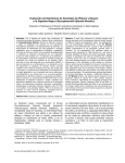
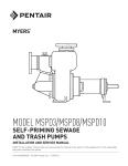
ME3H SUMP/EFFLUENT PUMP ME3F SUMP/EFFLUENT PUMP ME3H/ME3F SERIES SUBMERSIBLE SUMP AND EFFLUENT PUMPS INSTALLATION AND SERVICE MANUAL Automatic and manual models. Single phase power only – 115 or 230 volt. NOTE! To the installer: Please make sure you provide this manual to the owner of the equipment or to the responsible party who maintains the system. Part # 23833A305 | © 2012 Pentair Pump Group, Inc. | 11/14/12 NOTE: READ THESE INSTRUCTIONS CAREFULLY BEFORE ATTEMPTING TO INSTALL PUMP. CALIFORNIA PROPOSITION 65 WARNING: the discharge pipe using a minimum 4" tether length. The switch must float free from pump and basin wall. Plug the switch cord plug into a properly grounded, rated voltage receptacle. Plug the power cord into the back of the switch cord and tape the cords to the discharge pipe every 12". The power receptacle must be located outside the wet sump or basin due to the DANGER of current leakage. This product and related accessories contain chemicals known to the State of California to cause cancer, birth defects or other reproductive harm. DESCRIPTION AND APPLICATION ME3H and ME3F: Myers ME3H and ME3F Series Pumps are single seal units, available in automatic or manual, and are designed for use in effluent dosing, Septic Tank Effluent Pumping (S.T.E.P.) or normal sump and general dewatering applications where higher pressure is required. When used in effluent dosing or S.T.E.P. applications, the pump must be installed in a separate tank or compartment at the discharge side of the septic tank. NEVER INSTALL PUMP IN MAIN TANK WHERE SLUDGE COLLECTS. DO NOT USE PUMPS FOR RAW SEWAGE. On all duplex units or simplex installations with additional options like high water alarm, the power cord plug must be cut off and wired into a control panel or into a sealed junction box if used in wet sump or basin. The AWS-1 control also acts as a sealed junction box for connecting power cord to pump cord. MOTOR TYPE General: The pumps use a 1/3 HP shaded pole, 1550 RPM motor, and are available in 115 volt and 230 volt, single phase. Both the manual and automatic models come standard with a 20 ft. power cord. All automatic models come with a mechanical (mercury free) piggyback float switch. The pumps are designed to handle 3/4 inch spherical solids. The ME3H uses an engineered thermoplastic vortex impeller design to efficiently produce high pressures with low flows. The ME3F uses an engineered thermoplastic twovane solids handling impeller design to produce high pressures with medium flows. All pumps have a 1-1/2" discharge tapping. The motors used are pressed into the cast iron housings and surrounded by dielectric oil for superior heat dissipation. Both units have class A motor insulation, are available in single phase 115 and 230 volt with overload protection, and use a double sleeve bearing design. These pumps have no starting switches and do not require a control panel for simplex installation. SAFETY WARNINGS WARNING: Risk of electric shock. Pumps are supplied with a grounding conductor and grounding-type attachment plug on the power cord. To reduce the risk of electric shock, be certain that it is connected only to a properly grounded, grounding-type receptacle. DO NOT cut off ground pin or use an adapter fitting. DO NOT use an extension cord with this pump. Entire plug may be cut off if a control panel is used. WARNING! THESE PUMPS ARE NOT APPROVED FOR, AND SHOULD NOT BE USED IN SWIMMING POOLS OR FOUNTAINS. AIR LOCKING A pump is said to be air locked if water traps air in the pump and it cannot get out, thus preventing the pump from operating. All pumps have a GROUND WIRE that is connected to the motor. This wire goes to the receptacle or control panel which must be connected to a good outside GROUND. The sump pumps have a 1/16" air vent hole in the impeller chamber to let out trapped air. If this hole becomes plugged, pump may air lock. As a secondary precaution a 1/8" hole should be drilled in the discharge pipe below the check valve. The check valve should be 12 to 18 inches above pump discharge. Do not put check valve directly into pump discharge opening. When wiring this pump follow all local electrical and safety codes and ordinances as well as the most recent National Electric Code (NEC-ANSI/NFPA 70). LEVEL CONTROLS INSTALLATION The automatic models have a 20 ft. mechanical (mercury free), piggyback float switch. The 115 or 230 volt piggyback switch is tethered directly to the pump. The switch can optionally be mounted to WARNING: Basin or tank must be vented in accordance with local plumbing codes. These pumps are not designed for and CANNOT be installed in locations classified as hazardous in 23833A305 11/14/12 2 accordance with the National Electric Code ANSI/ NFPA 70. d. Check for burned-out motor. Occasionally lightning can damage a motor even with lightning protection. CAUTION: Never enter pump chamber after sewage or effluent has been in basin. Sewage water can give off methane, hydrogen sulfide and other gases which are highly poisonous. e. Where plug-in cords are used be sure contact blades are clean and making good contact. DO NOT USE PLUG-IN CORDS INSIDE A SUMP OR WET WELL. f. Level control ball or weight may be stuck on side of basin. Be sure it floats freely. For this reason, Myers recommends installing effluent pumps with a quick removal system. The quick removal system may be a union or Cam-Iok® coupling if the pipe or discharge hose is within reach from the surface, or a rail system type quick disconnect on deeper installations. See installation drawings for suggested installation. 2.Pump runs but does not deliver flow. The dosing tank or pumping chamber must be constructed of corrosion resistant materials and must be capable of withstanding all anticipated internal and external loads. It also must not allow infiltration or exfiltration. The tank must have provisions for antibuoyancy. Access holes or covers must be adequate size and be accessible from the surface to allow for installation and maintenance of the system. Access covers must be lockable or heavy enough to prevent easy access by unauthorized personnel. The pumping chamber holding capacity should be selected to allow for emergency conditions. a. Check for air lock. Start and stop pump several times; if this does not help it may be necessary to loosen a union in the discharge line to relieve air lock. b. Check valve may be installed backward. Check flow arrow on valve body. Check shut-off valve. It may be closed. c. Check vertical elevation. It may be higher than pump can develop. (See pump curve.) d. Pump inlet may be plugged. Remove pump to check. CAUTION: ALWAYS UNPLUG POWER CORDS OR TURN OFF ALL MAIN AND BRANCH CIRCUIT BREAKERS BEFORE DOING ANY WORK ON THE PUMP. If control panel is remote from pump, disconnect lead wires to motor so that no one can turn the circuit breaker back on. The discharge pipe must be the same size as the pump discharge, 1-1/2" or larger. In order to ensure sufficient fluid velocity to prevent any residual solids from collecting in the discharge pipe, it is recommended that a minimum flow of 2' per second be maintained. (12 GPM through 1-1/2" pipe, 21 GPM through 2" pipe and 46 GPM through 3" pipe.) It is recommended that PVC or equal pipe is used for corrosion resistance. A full flow (ball or gate) shut-off valve must be installed to prevent back flow of effluent if the pump must be removed for service. A check valve must be installed on pressure sewer systems and on other systems where conditions allow to prevent backflow and to reduce wear on the pump system. CAUTION: FOR ANY WORK ON PUMP OR SWITCH, ALWAYS UNPLUG POWER CORD. DO NOT TURN OFF CIRCUIT BREAKER OR UNSCREW FUSE. TO REPLACE AUTOMATIC FLOAT 1.Unplug the pump power cord from the back of the piggyback float plug. 2.Unplug the piggyback float plug from the power receptacle. 3.Remove the pump from the sump if access to the tether point is inaccessible. A high water alarm must be installed on a separate circuit from the pump circuit. The alarm should have the ability to be tested for proper operation. 4.Disconnect the switch from its tether point and remove from the discharge piping. 5.Retether the new cord to the pump or discharge piping. POINTS TO CHECK IF PUMP DOES NOT RUN OR DOES NOT RUN PROPERLY 6.Cable tie or tape the power and switch cords to the discharge piping. 1.Pump does not run or start when water is up in tank. 7.Plug the switch into the power receptacle. a. Check for blown fuse or tripped circuit breaker. 8.Plug the power cord into the switch plug. b. Check for defective level switch. 9.Fill basin and test switch operation. c. Where control panel is used, be sure H-O-A switch is in the AUTO position. If it does not run, turn switch to the HAND position and if the pump runs, the trouble is in the automatic electrical system. Have ELECTRICIAN make electrical checks. ALL PUMP REPAIRS SHOULD BE DONE AT AN AUTHORIZED MYERS SERVICE CENTER. 3 23833A305 11/14/12 23833A305 11/14/12 4 TYPICAL SECTION DRAWING FOR ME3H SERIES ME3H DIMENSIONAL DRAWING 8-13/16 5-1/4 11-1/8 12-23/64 10-45/64 6-33/64 2-1/16 5 3-7/16 23833A305 11/14/12 TYPICAL SECTION DRAWING FOR ME3F SERIES Cable Tie Now Shown ME3F DIMENSIONAL DRAWING 8-1/4 4-29/32 10-21/64 12-29/32 11-1/4 7-1/16 4-13/16 23833A305 11/14/12 6 7 23833A305 11/14/12 23833A305 11/14/12 8 9 23833A305 11/14/12 THIS PAGE INTENTIONALLY LEFT BLANK THIS PAGE INTENTIONALLY LEFT BLANK STANDARD LIMITED WARRANTY Pentair Myers® warrants its products against defects in material and workmanship for a period of 12 months from the date of shipment from Pentair Myers or 18 months from the manufacturing date, whichever occurs first – provided that such products are used in compliance with the requirements of the Pentair Myers catalog and technical manuals for use in pumping raw sewage, municipal wastewater or similar, abrasive-free, noncorrosive liquids. During the warranty period and subject to the conditions set forth, Pentair Myers, at its discretion, will repair or replace to the original user, the parts that prove defective in materials and workmanship. Pentair Myers reserves the right to change or improve its products or any portions thereof without being obligated to provide such a change or improvement for prior sold and/or shipped units. Start-up reports and electrical schematics may be required to support warranty claims. Submit at the time of startup through the Pentair Myers website: http://forms.pentairliterature.com/startupform/startupform.asp?type=m. Warranty is effective only if Pentair Myers authorized control panels are used. All seal fail and heat sensing devices must be hooked up, functional and monitored or this warranty will be void. Pentair Myers will cover only the lower seal and labor thereof for all dual seal pumps. Under no circumstance will Pentair Myers be responsible for the cost of field labor, travel expenses, rented equipment, removal/reinstallation costs or freight expenses to and from the factory or an authorized Pentair Myers service facility. This limited warranty will not apply: (a) to defects or malfunctions resulting from failure to properly install, operate or maintain the unit in accordance with the printed instructions provided; (b) to failures resulting from abuse, accident or negligence; (c) to normal maintenance services and parts used in connection with such service; (d) to units that are not installed in accordance with applicable local codes, ordinances and good trade practices; (e) if the unit is moved from its original installation location; (f) if unit is used for purposes other than for what it is designed and manufactured; (g) to any unit that has been repaired or altered by anyone other than Pentair Myers or an authorized Pentair Myers service provider; (h) to any unit that has been repaired using non factory specified/OEM parts. Warranty Exclusions: Pentair MYERS MAKES NO EXPRESS OR IMPLIED WARRANTIES THAT EXTEND BEYOND THE DESCRIPTION ON THE FACE HEREOF. Pentair MYERS SPECIFICALLY DISCLAIMS THE IMPLIED WARRANTIES OF MERCHANTABILITY AND FITNESS FOR ANY PARTICULAR PURPOSE. Liability Limitation: IN NO EVENT SHALL Pentair MYERS BE LIABLE OR RESPONSIBLE FOR CONSEQUENTIAL, INCIDENTAL OR SPECIAL DAMAGES RESULTING FROM OR RELATED IN ANY MANNER TO ANY Pentair MYERS PRODUCT OR PARTS THEREOF. PERSONAL INJURY AND/OR PROPERTY DAMAGE MAY RESULT FROM IMPROPER INSTALLATION. Pentair MYERS DISCLAIMS ALL LIABILITY, INCLUDING LIABILITY UNDER THIS WARRANTY, FOR IMPROPER INSTALLATION. Pentair MYERS RECOMMENDS INSTALLATION BY PROFESSIONALS. Some states do not permit some or all of the above warranty limitations or the exclusion or limitation of incidental or consequential damages and therefore such limitations may not apply to you. No warranties or representations at any time made by any representatives of Pentair Myers shall vary or expand the provision hereof. 1101 MYERS PARKWAY 490 Pinebush Road, Unit #4 ASHLAND, OHIO, USA 44805 CAMBRIDGE, ONTARIO, CANADA N1T 0A5 419-289-1144800-363-PUMP WWW.FEMYERS.COM Warranty Rev. 12/13