1
Installation
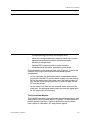
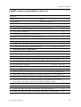
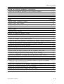
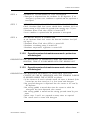
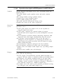
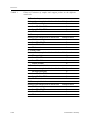
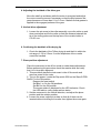
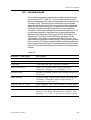
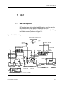
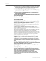
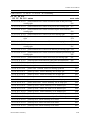
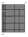
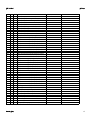
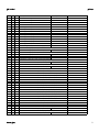
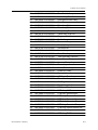
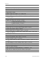
ILab600 system installation check list
Date
Instrumet model & S/N
Customer
Contact person
phone
FSE signature
Action
Checked
Environmental check-outs
Room temperature
O
Electrical requirements
O
Water supply/drain rquirements
O
DMS interconnection
O
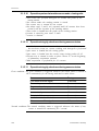
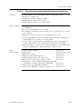
Instrumental check-outs
Check instrument crate
O
Check packing list
O
Check that PCBs, connectors and tubing are securely fastened
O
Perform system interconnection
O
Check the integrity of all cuvettes of reaction tray
O
Install ISE reagent & detergent solutions
O
Check grounding
O
Check ILab voltage settings
O
Install the personal computer - Install Windows NT & ILab600 sostware program O
SW program rev..............
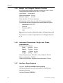
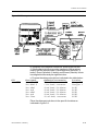
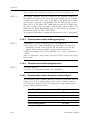
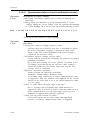
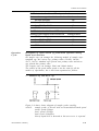
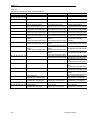
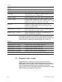
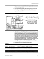
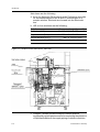
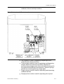
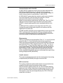
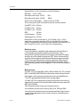
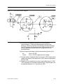
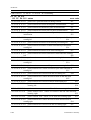
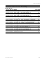
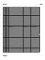
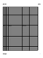
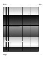
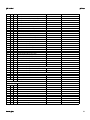
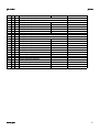
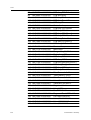
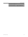
Perform the following DC voltage measurements:
Item
Location
Measured VDC
Range
Temperature contr. pcb
CN2/CN3 Pin 1-2
+4.9 to+5.2
Temperature contr. pcb
CN2/CN3 Pin 3-4
+14.5 to+15.5
Temperature contr. pcb
CN2/CN3 Pin 4-5
-14.5 to-15.5
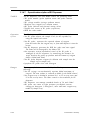
Driver Mother pcb
CN16/CN17Pin 1-4
+23.0 to+25.0
DC Power pcb
CN5/CN6/CN7 Pin 1-4
+12 to+14V
Lamp voltage
Lamp connector
+11.4¸+11.6
ISE Main pcb
TP 12-13
4.8 to 5.2VDC
ISE Main pcb
TP 14-15
23.0 to 25.0V
ISE Main pcb
TP 19-15
11.1 to 15.6V
ISE Main pcb
TP 16-17
14.25 to 15.75V
ISE Main pcb
TP 18-17
-14.25 to -15.75
2.18
Instrumentation Laboratory