1
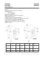
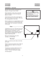
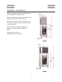
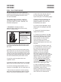
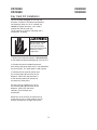
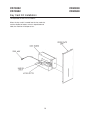
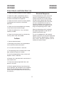
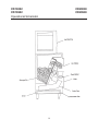
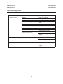
SERVICE/INSTALLATION MANUAL
HOTEL/MOTEL DISPENSER
GC Series Cuber Shown
CD10022
CD10522
ICE Series Cuber Shown
CD20030
CD20530
ICE-O-Matic
11100 East 45th Avenue
Denver, Colorado, USA 80239
Part Number 80701101
Print Date: 6/00
CD10022
CD10522
Introduction
CD20030
CD20530
To the owner or user. This product is a source of information about the installation, start up,
cleaning, maintenance and repair of the product.
The CD10022, CD10522, CD20030 and CD20530 are Ice-O-Matics brand
hotel/motel ice dispenser. The CD10022 is designed to use a Ice-O-Matic model GC300,
550, ECP 400, 550, 556 ice machine as the source for ice. The CD-200-30 is designed to use
a Ice-O-Matic model ICE 250, 400, 500 and 600 ice machine as the source of ice.
Ice from the cuber falls into the insulated hopper, where it is stored until needed. When a user
pushes the dispense button, a rotating wheel scoops the ice up and moves the ice to the top
of the hopper where there is an outlet to the ice chute.
Table of Contents
Specifications/Limitaions . . . . . . . . . . . . . . . . . . . . . . . . . Page 2
Installation
Kits
. . . . . . . . . . . . . . . . . . . . . . . . . . . . . Page 3 - 4
. . . . . . . . . . . . . . . . . . . . . . . . . . . . . . . Page 5 - 10
Final Check List/Initial Start Up/Electrical Sequence . . . . . . . . . . . . . . Page 11
Cleaning
. . . . . . . . . . . . . . . . . . . . . . . . . . . . . Page 13 - 14
Service Diagnosis
. . . . . . . . . . . . . . . . . . . . . . . . . . . Page 15
Removal and Replacement
. . . . . . . . . . . . . . . . . . . . . . . Page 16
Electrical Schematics . . . . . . . . . . . . . . . . . . . . . . . . Page 17 - 19
NOTE: The warning symbol where it appears in this
manual. It is an alert for important safety information
on a hazard that might cause serious injury.
NOTE: Keep this manual for future reference.
1
CD10022
CD10522
Specifications
CD20030
CD20530
Limitations:
• Must meet the same limitations as the cuber
installed on top of it:
o
• 50 F air minimum
• 100o F air maximum
• Must be installed indoors
• Must allow space to the right for air intake when
using air cooled machine.
• The CD10022 and CD10522 are compatible
only with Ice-O-Matics’ models GC 300, 550, ECP 400, 550, 556.
• The CD20030 and CD20530 are compatible only
with Ice-O-Matics’ models ICE 250, 305, 400, 500, 600.
• Must allow space for utility connections at the back.
• Must have a drain.
Model
Dimensions
(with legs)
Basic
Electrical
Finish
Ice Storage
Capacity (ARI)
MaxFuse
Size
Min Circuit
Ampacity
CD10022
22”x30”x50”
115/60/1
S. STEEL
90 lbs.
15
2.5
CD10522
22”x30”x50”
230/50/1
S. STEEL
90 lbs.
15
1.3
CD20030
30”x30”x53”
115/60/1
S. STEEL
140 lbs.
15
1.9
CD20530
30”x30”x53”
230/50/1
S. STEEL
140 lbs.
15
1.0
2
CD10022
CD10522
Installation: General
CD20030
CD20530
After the carton has been removed from the
dispenser, the legs may be installed.
Place flat portions of the carton on the floor
behind the dispenser and lay the dispenser
down on its back.
Thread the legs into the base of the dispenser.
Be sure that the legs are screwed in all the way.
Turn the leg levelers in all the way.
Move the dispenser to an upright postion and set
it in the location where it will be installed. Note
where the drain lines and electrical connections
will be made.
Drain:
The dispenser has a 3/4” FPT drain fitting at the
bottom center of the back panel. Connect 3/4”
rigid tubing to this connection, a vent is
recommended for most installations. Route the
drain tubing to the building drain. Follow all
applicable plumbing codes.
Because the tubing will be very cold,
insulation is recommended.
Electrical:
There is an electrical junction box on the lower
back panel.
Make the electrical connections there. Follow all
applicable electrical codes. Use a licensed
electrician.
The dispenser must be installed so that it is a
separate piece of equipment from the ice
machine. The drains and electrical supply
must be separate.
3
NOTE
Remove any packaging material
from inside the storage bin. Retain
keys for later use.
Check that gasket tape is on the
top outside edge of the dispenser
where the ice machine will rest.
CD10022
CD10522
Installation: Ice Machine
CD20030
CD20530
Check that gasket tape has been placed at the
outside edge of the dispenser top.
Place corner posts from the carton on top of the
dispenser, at the left and right corners.
Place the ice machine onto the dispenser. The
ice machine is heavy, use of a mechanical hoist
is recommended.
Carefully remove cardboard supports and
allow ice machine to rest on dispenser
gasket.
Follow all instructions for
installation of the ice machine.
4
CD10022
CD10522
Kits: Coin Mechanism
CD20030
CD20530
Kits are available to install a coin mechanism,
a room key mechanism or a key card mechanism.
All kits come with detailed instructions which
are also listed below.
8. Mount the timer and relay from the
kit in the control box. (See typical
layout of the parts in the following page).
Please follow these instructions carefully to
complete the addition of the coin mechanism
kit to the CD10022, CD10522, CD20030, and
CD20530 ice dispenser.
9. Remove wires #8 and #9 from the
control box. These wires will be replaced by different wires which will
be identified as #8 and #9.
10. Install the wires provided in the kit
following the wiring diagram provided
in the kit.
1. Disconnect the dispenser from its
electrical power supply (failure to do so may
result in a serious injury).
11. Reconnect the electrical power
supply to the machine.
12. Place an ice container in the drop
zone of the dispenser. Place a quarter
into the coin slide mechanism. Then
push and hold the safety interlock
switch. Now push in the coin
mechanism and release it. The dispenser should dispense ice into the ice
container.
Electrical shock hazard.
Electrical shock can
cause personal injury.
Disconnect power before
begining to service
components.
2. Unlock and remove the decorative front cover,
then remove the top front brace and the control
box cover.
13. Determine if the correct amount of
ice was dispensed. If more ice is needed, increase the time on the timer by
turning the timer adjustment dial
clockwise. If less ice is required,
decrease the time by turning the
adjustment knob counter-clock-wise.
The initial setting on the timer should be
approximately 4 on the knob, approximately 8 seconds. (Each segment on
the timer represents approximately
2 seconds). IMPORTANT: Make sure
to disconnect the power supply to the
machine when adjusting the timer.
3. Remove all wires from the push button switch.
Now remove the nuts that secure the push button
cover from the inside of the dispenser panel.Then
remove the cover from the dispenser. Now remove
the screws that secure the push button switch to
the cover and remove the push button switch.
4. Install the small cover plate which was
supplied in the kit.
5. Remove the larger cover plate which is located
below where the push button switch was located.
14. After all adjustments have been
completed and the dispenser operates
satisfactorily; attach the new
electrical schematic over the old one
that originally came with the machine
and install the coin collection box.
6. Install the mounting plate provided in the kit
using the nuts provided in the coin mechanism kit.
7. Secure the coin mechanism to the mounting
plate from inside the dispenser cabinet using the
screws, flat washers and lockwashers in the kit.
5
CD10022
CD10522
Kits: Coin Mechanism
CD20030
CD20530
15. Replace the control box cover, front
brace and decorative front cover. The
dispenser should now be restored to
service.
6
CD10022
CD10522
Key Kit Installation
This kit has been designed for use with the
CD10022, CD10522, CD20030 and CD20530 ice dispenser. When this kit is installed, ice cannot be dispensed unless a specific type of key is inserted into
the lock cylinder. The kit contains a universal mounting fitting for lock cylinders and a switching
mechanism.
NOTE: The user must supply their own lock
cylinders.
Electrical shock hazard.
Electrical shock can
cause personal injury.
Disconnect power before
begining to service
components.
1.Make sure all electrical power is disconnected
to the dispenser before attempting to install this kit.
2. Remove the front plastic molded front panel,
then remove the cover plate which is located below
the push button. This cover plate is held in place with
4 locknuts which are to be removed from the inside
of the cabinet.
3. Obtain a lock cylinder common to those used by
the establishment. Insert the cylinder in the brass
fitting supplied in the kit. Mark the amount of the
cylinder that extends beyond the brass fitting. Remove the cylinder from the brass fitting and cut off
the cylinder at the mark.
4. Insert the brass fitting into the hole in the cover
plate provided in the kit. Place switch mounting
bracket behind cover plate and over the brass fitting.
Next, add the plastic washer over the brass fitting
and behind the switch mounting bracket. Using the
locknut provided in the kit fasten the fitting in place
with the flats in a vertical position. Place thecylinder
in the fitting and secure it with the key slot parallel to
the flats on the fitting collar using the set screw
provided.
7
CD20030
CD20530
5. With a key in place, adjust the snap
action of the micro switch so that it
actuates when the key is inserted.
Now disconnect wire #8 and #9 from
the normally open (NO) terminal of the
dispense switch (S2) and reconnect it
to the normally open (NO) terminal of
the room key microswitch.
Connect wire #6 supplied in the kit to
the normally open (NO) terminal of the
dispense switch (S2) and to the
common (C) of the room key microswitch.
Check all of the wires and terminals
to make sure the unit is wired correctly
and all terminal connections are tight
and secure.
CD10022
CD10522
Key Kit Installation
CD20030
CD20530
The operation of this kit is as follows:
When the key is inserted into the lock cylinder,
a portion of the key will extend beyond the brass
fitting.
It is this part of the key that will actuate the kit
micro switch. Then when the dispense button swithch
is depressed and held; the machine will dispense ice.
8
CD10022
CD10522
Key Card Kit Installation
CD20030
CD20530
This kit has been designed for use with the
CD10022, CD10522, CD20030 and CD20530
ice dispenser. When this kit is installed, ice
cannot be dispensed unless a key card is
inserted into the key card slot.
The kit contains a universal mounting and a
microswitch assembly.
Electrical shock hazard.
Electrical shock can
cause personal injury.
Disconnect power before
begining to service
components.
1. Make sure all electrical power is disconnected
to the dispenser before attempting to install this kit.
2. Remove the plastic molded front panel,
then remove the cover plate which is located below
the push button. This cover plate is held in place
3. Now disconnect wire #8 and #9 from
the normally open (NO) terminal of the
dispense switch (S2) and reconnect it
to the normally open (NO) terminal of
the room key microswitch.
Connect wire #6 supplied in the kit to
the normally open (NO) terminal of the
dispense switch (S2) and to the
common (C) of the room key
microswitch.
Reconnect all of the wires and terminals to
make sure the unit is wired correctly and all
terminal connections are tight and secure.
9
CD10022
CD10522
Key Card Kit Installation
CD20030
CD20530
The Operation of this kit is as follows:
When the key card is inserted into the key card slot,
and the dispenser button switch is depressed and
held, the machine will dispense ice..
10
CD10022
CD10522
Final Check List/Initial Start Up
CD20030
CD20530
Electrical Sequence:
1. Check that electrical power has been supplied.
2. Check that a drain, separate from the ice
machine, insulated and made of rigid tubing,
has been connected to the dispenser.
Pushing the dispenser switch closes the
contacts to the gearmotor and to the
ice door solenoid. The ice door solenoid
will open and the dispensing wheel will
start to turn bringing ice to the ice chute,
and ice is released to fall into the ice
container supplied by the customer. The
machine will continue to dispense ice as
long as the dispensing switch is held.
3. Check that the ice machine has been properly
installed per the ice machine’s installation
directions.
4. Check that the machine/dispenser assembly
is level front to back and left ot right.
When the dispensing switch is released,
the dispensing wheel will stop and the
ice door solenoid will close.
5. Check that optional kits, if any, have been
correctly installed.
6. Check that the front panel key, coin box key,
and key card if used, are available.
This unit is equipped with and automatic
agitation cycle shich will cause the dispensing
wheel to rotate for approximately 3 seconds
every 2 hours. During this agitation cycle the
ice door will remain closed.
To Start:
1. Connect electrical power.
2. Go through ice machine start up procedures.
Let ice machine make two harvests.
3. Push vend switch button in and hold.
4. The dispensing whell will rotate and the vend
door solenoid will open the ice door.
5. Ice will be dispensed from the ice chute until
dispense switch is released.
6. Remove sink, and check drain area for leaks. If
none, replace sink.
7. Fill out the warrenty registration form, and
place it in the mail.
8. Give the operator the key(s) and instructions
on the operation and maintenance of the product.
Check that the operator knows who to call for
service, and has the product/service manuals for
the machines.
11
CD10022
CD10522
Operational Schematic
CD20030
CD20530
12
CD10022
CD10522
Cleaning
CD20030
CD20530
General Care and Ceaning:
Periodically inspect and clean the ice dispenser
to keep it operating at peak performance.
sweep arm securing the wheel to the
drive shaft. Remove the sweep arm
by rotating it in the counter clockwise
direction.
Wash the outside of the dispenser with warm
water and soap. Rinse off and dry.
6. Pull the wheel off the drive shaft and
leave it in the dispenser.
Cleaning and Sanitizing of the Ice
Storage Bin:
7. Mix a solution of 5 ounces of ice
machine cleaner to 1 gallon of warm
(95o F-115o F) water. Rubber gloves
and eye protection to be worn. Wash
the entire bin area and the delivery
area. Use a clean brush or cloth.
The minerals, chlorine and other impurities in the
water are rejected from the water during the
freeze cycle of the ice machine. These minerals
will collect in the storage bin. The ice storage bin
should be cleaned and sanitized every 90 days.
8. Rinse all areas washed with clean,
fresh water.
1. Remove all of the ice stored inside the
dispenser bin by holding in dispensing button
and shut off the ice maker.
9. Using the ice machine cleaning
solution, clean the ice grill, sink, and
water pan. Rinse these parts with
clean, fresh water.
Electrical shock hazard.
Electrical shock can
cause personal injury.
Disconnect power before
begining to service
components.
Ice machine cleaner
contains acids.
These compounds
may cause burns.
If swallowed, DO NOT
induce vomiting. Give
large amounts of water
or milk. Call physician
immediately! In case of
external contact, flush
with water.
KEEP OUT OF THE
REACH OF CHILDREN!
Moving parts in bin will
cause injury if hands
are in the way.
disconnect electrical
power before begining
procedures.
2. Disconnect the electrical power.
3. Locate key and remove front panel.
4. Remove top front panel (in front of ice machine)
5. Reach into the opening, locate the
13
CD10022
CD10522
Cleaning
CD20030
CD20530
10. Mix a solution of ice machine
sanitixer and water: 1 ounce of
household bleach to 2 gallons of
(95o F-115o F) water. Wash all interior
surfaces and the wheel withthe
sanitizer solution. Use a clean cloth.
11. Allow the parts to air dry.
12.Reassemble wheel and sweep arm onto
drive shaft.
13. Replace all panels.
14. Reconnect power, be sure ice machine is
switched back on.
14
CD10022
CD10522
Service Diagnosis
PROBLEM
Does not vend
CD20030
CD20530
POSSIBLE CAUSE
No ice
No power
Vend switch open
Check power supply
Check / replace vend switch
Sink interlock switch open
Check / replace sink interlock
switch
Machine is not level
Ice jams in chute
Front panel not on all the way
Gear motor open
Relay does not operate
Ice door does not open
Leaks water
Reinstall panel
Check/replace gearmotor
Check wiring
Check power to relay
Check for burnt contacts
Check for power to solenoid
Does not vend, no ice
Check for disengaged door
linkage
Check/replace drive shaft
Check the above, plus
coin switch
Check wiring
Check timer
Bin drain leaks
Check bin drain connections
and fittings
Drive shaft broken
Coin Mechanism
PROBABLE FIX
Check ice machine
Check for clogged bin drain
tubing
15
CD10022
CD10522
Removal and Replacement
CD20030
CD20530
Dispense Wheel:
1. Remove all of the ice stored inside
the dispenser bin and shut off the
ice maker.
Electrical shock hazard.
Electrical shock can
cause personal injury.
Disconnect power before
begining to service
components.
2. Disconnect the electrical power.
3. Remove ice machine from dispenser.
4. Remove large dispenser top panel.
5. Reach into opening, locate the
sweep arm which secures the wheel to
the drive shaft. Remove the sweep arm.
Gear Motor:
1. Disconnect electrical power.
2. Locate key and remove front panel.
6. Pull the wheel off the drive shaft and
remove it from the dispenser.
3. Remove dispenser wheel.
7. Revese steps to reassemble.
4. Disconnect wires at gearmotor.
5. Remove 4 bolts securing gearmotor bracket to
cabinet.
6. Pull gearmotor out of cabinet.
7. Remove gearmotor from bracket.
8. Reverse steps to reassemble.
16
CD10022
CD20030
CD10522
CD20530
Standard With Room Key Kit or Card Kit Electrical Schematic
17
CD10022
CD20030
CD10522
CD20530
Standard With Room Key Kit or Card Kit Electrical Schematic
18
CD10022
CD10522
With Coin Mechanism Electrical Schematic
19
CD20030
CD20530
SERVICE HISTORY
MODEL NUMBER: ______________ SERIAL NUMBER: _____________
____________________________
____________________________
____________________________
____________________________
____________________________
____________________________
____________________________
____________________________
____________________________
____________________________
____________________________
11100 East 45th Avenue • Denver, Colorado, USA 80239 • Telephone: (303) 371-3737 • Facsimile: (303) 371-6296