1
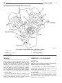
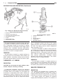
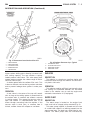
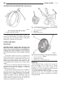
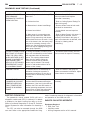
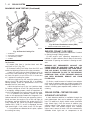
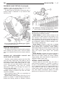
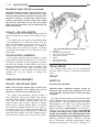
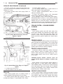
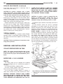
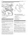
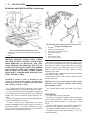
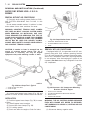
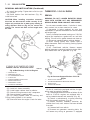
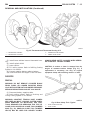
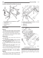
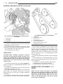
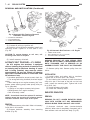
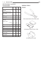
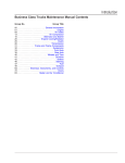
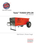
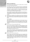
7-6
COOLING SYSTEM
DN
DESCRIPTION AND OPERATION (Continued)
WATER PUMP BYPASS—4.7L
DESCRIPTION
The 4.7L engine uses an internal water/coolant
bypass system. The design uses galleries in the timing chain cover to circulate coolant during engine
warm-up preventing the coolant from flowing
through the radiator. The thermostat uses a stub
shaft located at the rear of the thermostat (Fig. 9) to
control flow through the bypass gallery.
Fig. 7 Radiator—Typical
1 – RADIATOR
2 – A/C CONDENSER (IF EQUIPPED)
3 – TRANSMISSION AUXILIARY OIL COOLER
antifreeze in the coolant mixture. Additional lubrication is not necessary.
Fig. 8 Water Pump Location—Typical
1
2
3
4
–
–
–
–
WATER PUMP BYPASS HOSE
FAN BLADE ASSEMBLY
VISCOUS FAN DRIVE
WATER PUMP AND PULLEY
OPERATION
A centrifugal water pump circulates coolant
through the water jackets, passages, intake manifold,
radiator core, cooling system hoses and heater core,
this coolant absorbs the heat generated when the
engine is running. The pump is driven by the engine
crankshaft via a drive belt.
Fig. 9 Water/Coolant Bypass Flow and Thermostat—
4.7L Engine
1
2
3
4
5
–
–
–
–
–
FROM HEATER
FROM RADIATOR
TO WATER PUMP
ENGINE BYPASS
THERMOSTAT
OPERATION
When the thermostat is in the closed position the
bypass gallery is not obstructed allowing 100% flow.
When the thermostat is in the open position the stub
shaft enters the bypass gallery obstructing bypass
coolant flow by 50%. This design allows the coolant
to reach operating temperature quickly when cold,
while adding extra cooling during normal temperature operation.