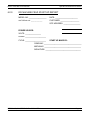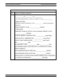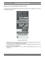
1
INSTALLATION, OPERATION
&
MAINTENANCE MANUAL
BERG B-AR, B-W SERIES SHELL-ICE MAKER
BERG CHILLING SYSTEMS INC.
Operation & Maintenance Manual
For 24 hour service inquiries, Please call
(416) 755 – 2226
BERG B-AR, B-W SERIES SHELL-ICE MAKER
Page 2
BERG CHILLING SYSTEMS INC.
Operation & Maintenance Manual
BERG SERIES SHELL-ICE MAKER
OPERATION & MAINTENANCE MANUAL
CONTENTS
Section
Description
1.0.0
2.0.0
3.0.0
4.0.0
5.0.0
6.0.0
7.0.0
8.0.0
9.0.0
Introduction
Installation and Start-Up Instructions
Various Positions and Settings
Schneider Controller
Enclosed Information
Ice Machine Field Start Up Report
Limited Warranty
Suggested Spare Parts List Parts
Component Specifications
BERG B-AR, B-W SERIES SHELL-ICE MAKER
Page 3
BERG CHILLING SYSTEMS INC.
Operation & Maintenance Manual
1.0.0 INTRODUCTION
Your BERG chilling system has been carefully assembled and engineered to give trouble free
service with a minimum of maintenance.
1.1.0
The simplicity of operation and maintenance of the SHELL ICE MAKER ICE
MACHINE is its unique feature. Any mechanic with the basic knowledge of
refrigeration cycles will be able to keep it operating at peak efficiency.
1.2.0
Before leaving our plant, each machine is tested, operated, and capacity
checked. For air cooled models, refrigerant is pumped down into receiver and
valves are closed before shipment.
Occasionally, minor adjustments during start-up and operation are necessary to
compensate for such differences as water pressure, water temperatures or
ambient temperatures.
1.3.0
Shipped inside the electrical panel door, you will find:
• Our service manual
• Electrical diagram
• Piping and Instrumentation Diagram
1.4.0
Before you begin to install and start your unit, we urge you to carefully read
through and digest this literature to familiarize yourself with its contents.
1.5.0
This service manual describes the following type of ice machine:
(a) Shell Ice Maker with a water cooled condenser.
(b) Shell Ice Maker with an air cooled condenser.
1.6.0
On the next few pages, you will see sketches and drawings showing major
components, details of site connections, water piping, and refrigeration piping.
The main frame size, number of evaporator tubes and condenser fans may,
however, vary with models.
1.7.0
In line with our CONTINUOUS IMPROVEMENT policy, other models are added
to the existing standard models and regularly updated product catalogues are
available. Inquiries can be made on special requirements to come up with
custom made products.
BERG B-AR, B-W SERIES SHELL-ICE MAKER
Page 4
BERG CHILLING SYSTEMS INC.
Operation & Maintenance Manual
2.0.0
INSTALLATION AND START-UP INSTRUCTIONS
2.1.0
Un-crate the unit, being careful not to damage external panels.
2.2.0
Set unit in permanent location in level position with bottom channel of unit frame
as reference.
Anchoring of this unit to concrete or wooden floor is not necessary. However,
rubber isolations are recommended if the unit is mounted directly on steel
structure.
Set remote air cooled condenser in permanent location at an elevated position,
at least five feet (1.52 meters) over and above the height of the refrigerant return
line. See attached diagram at end of manual for visual reference.
2.3.0
For preventing any possible damage to evaporator tubes during shipment,
precut polyethylene cushions are inserted between tubes and spaces between
end tubes and ice making section end walls.
2.4.0
Site Connections Required
Water drains necessary are;
•
One 1” (25mm) drain from sump
Suggested drain routing is shown on enclosed drawing for site connection.
Pipe water supply for ice making to the ½” (13mm) line.
NOTE:
On models producing 7 tons of ice and above per day, a low water pressure
control is incorporated to prevent the compressor from operating when the water
pressure is inadequate (12 psig 85 KPa min.). On small models, a float switch is
incorporated with the circulating pump to prevent the system from operating with
critically low water level inside the water tank.
For Remote Cooled Models
Make refrigerant line connections between main unit and the remote condenser
(see enclosed drawing on remote air cooled units).
2.5.0
Electrical Connections Required
Open electrical panel door by releasing the door latches for lock screws. Make
electrical connections through conduit where shown. Feed wire size required for
the machine should be suitable for K.V.A. connected load rating indicated on
nameplate.
BERG B-AR, B-W SERIES SHELL-ICE MAKER
Page 5
BERG CHILLING SYSTEMS INC.
Operation & Maintenance Manual
For Remote Air Cooled Models
Make electrical connections between the electrical panel on main unit and the
remote condenser fan or condensing unit.
Make electrical connection for power supply to the remote condenser fan or
condensing unit.
Voltage required and furnished should be checked at this time.
Follow recommendations as per wiring diagram, and local electrical code
applicable in your area.
2.6.0
Open suction and discharge valves on compressor, and also open inlet and outlet valves on
receiver (air cooled models), or condenser (water cooled models).
2.7.0
Check system for refrigeration leaks.
2.8.0
Turn main circuit breaker to “ON” position to energize crankcase heater on the
compressor. This heater should be left on for at least 24 hours before
starting up the compressor. Inside electrical panel turn screw drive switch and
water pump switch to “manual” position. Check water flowing down on inside
and outside surfaces of evaporator tubes. A ball valve is provided on the pump
discharge so that water spray from outer ring and inside nozzle can be adjusted,
and over-spray (higher than the outer ring and nozzle horizontal levels) can be
avoided: water should be streaming evenly down the tube and covering all tube
surfaces. Check the rotation of the auger: auger should turn clockwise. Turn
screw drive switch and water pump switch to “automatic” position.
2.9.0
Make sure that water supply valve is fully open. Make sure that water tank fills,
and water fill valve shuts off automatically.
2.10.0
Check to see that oil level is 1/3 to ½ up on compressor sight glass.
2.11.0
To operate machine please see Schneider Controller.
NOTE:
Final thickness adjustments are done at the site.
2.12.0
During freeze cycle, the liquid solenoid valve will open, and during harvest cycle,
the hot gas solenoid valve will open, thereby energizing one of the two indicating
lights located on the electrical panel door.
2.13.0
The ice machine is fitted with a water tank water level control, adjust water level
with respect to the type of control it is fitted with as follows:
BERG B-AR, B-W SERIES SHELL-ICE MAKER
Page 6
BERG CHILLING SYSTEMS INC.
Operation & Maintenance Manual
The water fill valve (see enclosures) measures water level by means of a
diaphragm that responds to water head. Diaphragm movement drives a servo
type main valve which controls the flow of water into the tank. The adjusting
knob is factory set to maintain 5” (125mm) water level in the tank. Turning the
knob clockwise or counter-clockwise raises or lowers the level; minimum water
level is 4” (102mm) above the fill valve centerline.
The water level in the tank should be maintained at approximately 1” (25mm)
below overflow stand-pipe for normal water conditions during freeze cycle.
2.14.0
Re-check oil level and check oil pressure which should be 12 to 18psi (85 to 130
KPa) above suction pressure. Always confirm oil pressure and oil level on
manufacturer’s manual of compressor package.
2.15.0
Check the voltage and current being drawn by the machine at electrical supply.
Compare it with the total running amps indicated on the panel nameplate. Also
check running amps of various components on the machine and compare with
those mentioned on the shop test sheet. A considerable difference may suggest
a problem and should be corrected before proceeding further.
2.16.0
On normal operation, if desired that, the compressor and the system will be
stopped, turn selector switch to “OFF” position.
NOTE:
To stop the machine anywhere in the cycle because of a problem, an
emergency stop push button is provided. After the “E-Stop” push button is
pressed, for additional safety turn to “OFF” selector switch.
2.17.0
If compressor is shut off by lube-oil safety switch, or if control circuit breaker is
opened, reset button(s) must be pushed before compressor can be restarted.
Do not reset safety controls more than once before determining cause of shutdown.
NOTE:
If compressor package shuts down due to low oil, use a REFRIGERANT
RECOVERY UNIT to withdraw refrigerant inside the package and transfer it
back to the liquid receiver, before adding oil. The procedure will facilitate easy
start up after sufficient amount of oil has been added. For where to add oil,
please consult manufacturer’s manual of the compressor.
2.19.0
If ice machine is one of the many related machines in the ice plant system,
carefully read instructions how it coordinates with the whole system, instruction
on electrical coordinates are usually found stated under NOTES of electrical
schematic. Usually an ICE PLANT SYSTEM manual is provided, explaining the
coordinated operation of the ice machine with the other related machineries.
BERG B-AR, B-W SERIES SHELL-ICE MAKER
Page 7
BERG CHILLING SYSTEMS INC.
3.0.0
VARIOUS POSITIONS AND SETTINGS
3.1.0
Normal Valve Positions
3.1.1
Open
•
•
•
•
Operation & Maintenance Manual
Compressor suction and discharge service shut-off valves.
Receiver or condenser inlet and outlet valves for refrigerant
Make up water supply valve.
Cooling water inlet and outlet valves on condenser (water cooled models
only).
3.1.2
Closed
• Compressor oil drain valve closed and capped.
• Accumulator oil drain valve closed and capped.
• Refrigerant charge valve closed and capped.
3.2.0
Normal Control Settings
(a) LP switch (factory set) – DO NOT CHANGE
(b) OFS Oil failure control (factory set) – DO NOT CHANGE
(c) Thermostatic expansion valves set for 8°F (14.4°C) degree superheat.
(c) Water pressure control set for 12 psig (85 KPa).
NOTE:
Always consult manufacturer’s manual of compressor package on safety control
settings.
3.3.0
Normal Operating Pressures
During the operation of the ice machine, the compressor is set to operate at
approximately 260 psig (1790 Kpa) head pressure during the freeze cycle.
At start of harvest, the head pressure will drop to approximately 175 psig (1210
KPa) and will rise to approximately 205 psig (1410 KPa).
Suction pressure during freeze cycle should be approximately 50 psig (345
Kpa), and at the time the ice drops, rises to 70 to 80 psig (480 to 550 KPa).
Immediately after harvest it will drop gradually to approximately 50 psig (360
KPa) and will then level out at approximately 40 psig (330 KPa).
3.4.0
Bin Limit Control Operation (If system is fitted with one).
As ice is discharged to the ice bin, ice will start to pile up inside the bin. A bin
limit control is installed to stop the ice machine when the ice pile reaches the
desired maximum level. A lighted red indicating light (ice limit control) on the
electrical panel box will indicate that the bin is full.
BERG B-AR, B-W SERIES SHELL-ICE MAKER
Page 8
BERG CHILLING SYSTEMS INC.
Operation & Maintenance Manual
Make sure that the “ice limit control” light is off when restarting the ice machine.
Follow procedure 2.11.0, on start-up of the machine.
NOTE:
When “Ice limit control” light stays on despite that the bin ice level had already
lowered, check the proximity probe and make sure that there are no solids within
ten inches (250mm) in front of it.
When Ice bin is with a RAKE ASSEMBLY SYSTEM, when full bin limit is
reached, an input signal to the controller will initiate an output relay to cut off the
ice machine main control circuit and stops the ice machine.
BERG B-AR, B-W SERIES SHELL-ICE MAKER
Page 9
BERG CHILLING SYSTEMS INC.
4.0.0
Operation & Maintenance Manual
SCHNEIDER CONTROLLER
This model Ice Machine uses adjustable timers to control the ice making, harvest and ice subcooling time.
4.1.0
FEATURES
The Schneider Controller provides comprehensive monitoring and alarm features covering
compressor operation, freeze cycle, harvest cycle, water tank level, auger drive operation, and
ice-bin level (optional).
It features four timers, all with adjustable pre-sets (within set limits) to customize the operation
of the ice machine:
TIMER NAME
TIMER RANGE
Ice Thickness
3 - 30 minutes
Harvest
Termination
0 - 10 minutes
Sub-cool
0 - 30 seconds
Condenser
FUNCTION
Controls the thickness of the ice (6 min. corresponds
to ¼” thickness)
Trips an alarm if the harvest cycle fails to terminate
before the set time
Used to produce colder, dryer ice: Shuts off the
water pump but remains in freezing mode for the set
time. This reduces the temperature of the ice
making it colder and dryer.
Delays start of compressor until water flows through
the condenser
BERG B-AR, B-W SERIES SHELL-ICE MAKER
Page 10
BERG CHILLING SYSTEMS INC.
5.0.0
•
•
•
•
•
•
•
•
•
•
•
•
Operation & Maintenance Manual
ENCLOSED INFORMATION
Water pump
Low water pressure control
Lube oil Protection control
Refrigeration HLP control
Thermostatic expansion valve
Liquid solenoid valve
Hot gas solenoid valve
Filter drier
Water fill valve
Programmable logic controller
Pressure regulators
Compressor manual and parts list
BERG B-AR, B-W SERIES SHELL-ICE MAKER
Page 11
BERG CHILLING SYSTEMS INC.
6.0.0
Operation & Maintenance Manual
ICE MACHINE FIELD START UP REPORT
MODEL NO: __________________
DATE: _______________________
UNIT SERIAL NO. ______________
CUSTOMER: ___________________
SITE ADDRESS: _________________
POWER SOURCE:
VOLTS: ________________
PHASE: _____________________
CYCLE: _____________________
START UP MADE BY:
COMPANY: ______________________________________
MECHANIC: _____________________________________
SIGNATURE: ____________________________________
BERG B-AR, B-W SERIES SHELL-ICE MAKER
Page 12
BERG CHILLING SYSTEMS INC.
Operation & Maintenance Manual
START UP AND FINAL ADJUSTMENTS
ITEM
NO
1
(READINGS TAKEN AFTER FINAL ADJUSTMENTS AND AFTER THREE COMPLETE
CYCLES – FREEZING & HARVEST)
AMPS DURING FREEZE CYCLE AT MAIN DISCONNECT
L1___________ L2___________ L3___________
2
SUCTION PRESSURE AT END OF FREEZE CYCLE _____________
PSI/KPa SUCTION
3
PRESSURE AT END OF HARVEST CYCLE _______________PSI/KPa DISCHARGE
PRESSURE
4
DURING FREEZE CYCLE _______________ PSI/KPa
5
AT RECEIVER:
PRESSURE TAKEN AT OUTLET VALVE DURING FREEZE CYCLE
_________________ PSI/KPa
OUTSIDE AMBIENT TEMPERATURE ______________ deg F/deg C
WATER SUPPLY TEMPERATURE ______________deg F/deg C
6
WATER TANK TEMPERATURE _______________ deg F/deg C
7
MIN. _______________ SEC
8
ICE HARVEST CYCLE: _____________ MIN. _____________ SEC.
9
ADJUSTMENTS MADE: (INCLUDE ONLY IF ORIGINAL SETTINGS
WERE CHANGED)
HIGH PRESSURE SWITCH SETTING _______________ PSI/KPa
LOW PRESSURE SWITCH SETTING _______________ PSI/KPa
WATER LEVEL AT WATER TANK DURING FREEZE CYCLE FROM END
OF OVERFLOW STANDPIPE: _______________ INCH/MM
BERG B-AR, B-W SERIES SHELL-ICE MAKER
Page 13
BERG CHILLING SYSTEMS INC.
Operation & Maintenance Manual
Caution
For Ice Machines:
Damage, Failures or poor performance associated with the following conditions are not
covered by warranty.
•
•
•
•
•
•
•
•
•
•
•
•
•
•
•
•
•
•
•
Freight Damage
Lack of proper maintenance
Misapplied, unstable or imbalanced power supply
Incorrect or loose electrical connections
Blown fuses
Incorrect phasing or rotation of fans, pumps, motors or compressors
Unauthorized adjustments
Tampering with valves or control settings
Leaks
Failure of components due to over pressurization
Improper refrigerant charge
Failure to initiate power, 12 hours prior to start-up of the ice machine
By-passing of any safety devices or pressure controls
Dirty supply water
Failure to provide adequate bleed off
Fouling or plugging of components
Operating the system with dirty evaporator tubes
Operating the system with dirty condenser
Operating the equipment outside of the original design specifications
•
•
•
Poor refrigerant piping practices
Locating the condenser below the elevation of the ice machine return connection
Locating a remote condenser in excess of 40 linear feet from the ice machine
without consulting with the factory
Improper refrigerant line size(s) to or from rooftop condensers
Improper or poor rooftop condenser location
Improper evacuation of refrigerant lines prior to installation of refrigerant and
start up
•
•
•
Note: All consumable items are not covered by warranty.
Example: Oil, filters, fuses, fan belts, refrigerant.
BERG B-AR, B-W SERIES SHELL-ICE MAKER
Page 14
BERG CHILLING SYSTEMS INC.
Operation & Maintenance Manual
SERIAL PLATE & EQUIPMENT IDENTIFICATION
A serial plate like the SAMPLE shown below has been affixed to the apparatus, and it gives
the following information:
(example of Serial Plate)
•
•
•
Whenever using this manual, check first that the serial number on the inside cover is
identical to that on the serial plate of the equipment.
In all correspondence with BERG, please refer to the manufacturing serial number, for
true identification of the equipment.
Whenever contacting BERG, be sure to state the manufacturing serial no.(s), and
model no.(s).
BERG B-AR, B-W SERIES SHELL-ICE MAKER
Page 15
BERG CHILLING SYSTEMS INC.
7.0.0
Operation & Maintenance Manual
Limited Warranty
Berg Chilling Systems Inc. (“Berg”) warrants to Buyer that upon delivery to Buyer the Products
purchased hereunder shall conform to the applicable Seller’s specifications as provided in the
quotation. Except as are contained herein, Berg makes no warranties, conditions, guarantees
or representations relating to the Products, express or implied, statutory or otherwise. The
Seller warrants all Products it manufactures to be free from defects in workmanship and
material when used under conditions recommended by us. The Seller’s obligation under the
warranty is limited to repair or replace or otherwise make good, at our factory, any parts
which, within one year after date of shipment of equipment of our manufacture to the original
purchaser, after being returned to us with transportation prepaid, and upon our examination,
shall disclose to our satisfaction to have been defective. The Seller neither assures, nor
authorizes any other persons to assume for us, any liability in connection with the sales of our
equipment except under the conditions of this warranty. The warranty does not cover any
field (on site) labour charges for replacement of parts, adjustment, repairs, or any other work
done. This warranty shall not apply to any Product or apparatus which in our opinion has been
subject to misuse, negligence, or pressures in excess of limits recommended by us, or which
have been repaired or altered outside Berg’s factory or which have had the serial number(s)
removed or defaced. This warranty does not cover refrigerant gas, nor does it cover any
apparatus damaged from freezing of water or heat transfer fluid. Replacement or repair of
defective material will be EX WORKS our factory, and will assume any used portion of this
warranty. All defective parts become the property of Berg and must be returned within fifteen
(15) days of the replacement date, transportation prepaid, as advised by Berg, to become
eligible for replacement under this warranty. Warranty Claim Forms, found in the Product
Owner’s Manual, must accompany all warranty claims and parts returns or this warranty shall
not apply. Berg is not responsible for any sales, use, excise, duty or any other applicable
taxes associated with the replacement of parts under this warranty. This warranty is only
effective with all the terms and conditions of the Product quote being met, and it is understood
that time is of the essence in this agreement. Repair or replacement of products not of our
manufacture will be limited to the warranty of the manufacturers of such products. Seller shall
transfer to Buyer whatever transferable warranties and indemnities Seller receives from the
manufacturers of any subcomponents of the Products, if any, including any transferable
warranties and indemnities in respect of patent infringement. See the Product Service Labour
Policies in your Product Owner’s Manual for possible extensions to this Warranty.
This is an expressed warranty of merchantability and or fitness for a particular purpose; all
other implied warranties and any liabilities not based upon contract are hereby disclaimed and
excluded by this warranty.
In accordance with Section 7 of our Standard Terms and Conditions of Sale, under no
circumstances shall Berg Chilling Systems Inc. be liable for loss of prospective or speculative
profits, or special, indirect, incidental, or consequential damages.
This warranty is a part of the Standard Terms and Conditions of Sale of Berg Chilling Systems
Inc.
BERG B-AR, B-W SERIES SHELL-ICE MAKER
Page 16
BERG CHILLING SYSTEMS INC.
Operation & Maintenance Manual
Service Labour Policy
Berg’s Service Labour Policy extends the One (1) Year Limited Warranty to include labour on
a limited basis, to the original purchaser only (see the Limited Labour Allowance Schedule in
your Product Owner’s Manual for allowable service hours). Berg will provide a Service
Technician or reimburse the Buyer in accordance with this Policy, to diagnose the problem,
repair or replace or otherwise make good, any part of equipment of our manufacture, which
within one year after the date of shipment to a destination within Canada or continental United
States of America (“the Territory”), and upon our examination, shall disclose to our satisfaction
to have been defective. If the Product or equipment is located outside “the Territory”, our
limited warranty only, ex works our factory, shall apply for one year from the date of shipping
(see Standard Terms and Conditions of Sale). Berg neither assures, nor authorizes any other
persons to assume for us, any liability in connection with the sale of our equipment except
under the conditions of this Policy. This Service Labour Policy does not apply to Temperature
Control Units (TCU’s).
The Service Labour Policy does not cover any field (on site) labour charges during overtime
hours (5:00pm to 8:00am or during weekends and holidays) nor does it cover charges, labour
or otherwise, associated with travel and accommodation, adjustments and maintenance, or
work done outside of Canada and continental USA. Any cost differential for overtime labour
charges will be the responsibility of the Buyer. Service Labour rates applied to the Limited
Labour Allowance Schedule, will be the mean rate, as determined by Berg, of the equipment
destination service area.
This Policy is voided and shall not apply if in our opinion, the Product has been subject to
misuse, negligence, or pressures in excess of limits recommended by Berg, or which have
been repaired or altered outside Berg’s factory or authorization or which have had the serial
number(s) removed or defaced. This Policy does not cover refrigerant gas or any labour
associated with its evacuation or replacement nor does it cover any Product or apparatus
maintenance or any apparatus damaged from freezing of water or heat transfer fluid. Any
work determined to be associated with the above will be the responsibility of the Buyer.
Berg is not responsible for any sales, use, excise, duty or any other applicable taxes
associated with the replacement of parts or labour under this Policy. This Policy is only
effective with all the terms and conditions of our quote being met, and it is understood that
time is of the essence in this agreement. This Policy is not transferable.
All Service Policy Labour must be authorized by Berg prior to any work being performed and
must have a Berg Purchase Order issued specifically for the work. Warranty and Service
Labour Claim Forms, found in the Product Owner’s Manual, must accompany all Service and
Warranty claims and parts returns or this Policy shall not apply. All defective parts become
the property of Berg and must be returned within fifteen (15) days of the failure, transportation
prepaid, as advised by Berg, to become eligible for replacement under this policy.
Products not of our manufacture do not qualify for this Service Labour Policy, and will be
limited to the warranty of the manufacturers of such Products.
BERG B-AR, B-W SERIES SHELL-ICE MAKER
Page 17
BERG CHILLING SYSTEMS INC.
Operation & Maintenance Manual
This Policy is a part of the Standard Terms and Conditions of Sale of Berg Chilling Systems
Inc.
Warranty Claim Procedure
Labour warranty, will only be allowed in those situations where defects have occurred as a
direct result of factory workmanship or defects in materials.
Claim Procedures:
• Consult the Factory immediately of any problems you are having with your equipment.
Phone 416-755-2221 or fax 416-755-6022.
•
If required Berg will supply contact information for the local authorized Berg Service
Contractor in your area; or if you wish you can use your own contractor, provided he is
licensed and qualified as required by local governing authorities and it is agreed upon
by Berg.
•
After the contractor has arrived on site and determined the cause of the problem; the
contractor must consult with the factory before proceeding with any repairs.
•
Once you have had your equipment repaired, complete the “Warranty Claim Form.” All
claims must be submitted on the Warranty Claim Form” found in the owners manual.
•
A signed service report from the Contractor detailing all work performed and an invoice
copy must accompany the “Warranty Claim Form.”
•
Claims must be faxed to “Berg Service Department” @ 416-755-6022 no later than 15
days after the failure has occurred.
•
Claims in excess of the “Limited Labour Allowance Schedule” may not be processed.
•
Berg reserves the right to adjust and/or refuse any claims that appear excessive or fails
to meet the Claims Procedure.
•
No claims will be processed if defective parts are not returned to Berg prepaid.
Use the “Limited Labour Allowance Schedule”[found in the owner’s manual] as a guide to
calculate the amount Berg will reimburse for required repairs on equipment found to be
defective. The schedule shows the maximum man-hours, which will be reimbursed at the
normal hourly rate of $54.00/Hr.
•
•
•
•
•
•
Berg will not pay for:
Labour at overtime or premium rates
Labour in excess of the “Limited Labour Schedule”
Service charges, mileage, travel expenses of any kind
Miscellaneous materials
Freight
Taxes or any special fees
BERG B-AR, B-W SERIES SHELL-ICE MAKER
Page 18
BERG CHILLING SYSTEMS INC.
Operation & Maintenance Manual
LIMITED LABOUR ALLOWANCE SCHEDULE
MAX. ALLOWANCE MAN HOURS
DESCRIPTION OF
FAILED COMPONENT
SIZE IN HP
REPAIR
REPLACE
3-10 HP
15-25 HP
30-40 HP
Over 40 HP
1
2
2
4
4
6
8
10
Leaks
All
2
2
Electrical Wiring, Controls,
Microprocessors
All
1
2
Refrigerant Valves or
Components
All
1
2
Motors
1-10
10 and Up
1
2
2 1/2
4
Pumps
All
2
3
Compressor
MAX. ALLOWABLE MAN HOURS
Diagnostic
1
Miscellaneous
1
BERG B-AR, B-W SERIES SHELL-ICE MAKER
Page 19
BERG CHILLING SYSTEMS INC.
Operation & Maintenance Manual
Service Labour Claim Procedures
Using the “Limited Labour Allowance Schedule” [above] as a guide to calculate the amount
Berg will reimburse for required repairs to equipment found to be defective.
This schedule shows the maximum man-hours, which will be reimbursed at the normal hourly
rate of $54.00/Hr.
Labour warranty, will only be allowed in those situations where defects have occurred as a
direct result of factory workmanship or materials.
Claim Procedures:
All claims must be submitted on Berg’s “Warranty Claim Form.”
Claim forms are found in the equipment owner’s manual or can be supplied upon request.
If a contractor is used to make the repairs, a signed service report and a company invoice
must accompany the “Warranty Claim Form.”
Claims must be faxed to “Berg Service Department” @ 416-755-6022 no later than 15 days
after the failure has occurred.
Claims in excess of the “Limited Labour Allowance Schedule” will not be processed.
BERG B-AR, B-W SERIES SHELL-ICE MAKER
Page 20
BERG CHILLING SYSTEMS INC.
Operation & Maintenance Manual
Warranty Claim Form
Fax to: Berg Service Dept.
416-755-6022
Claim #:
Date:
Claim Submitted By:
Company:
Address:
Job Name:
Address:
Phone #:
Fax #:
Phone #:
Fax #:
Berg Model #:
Voltage:
Serial #:
Date of Failure:
Date of Original Start-Up:
Details of Failure
Describe the nature of the failure.
Requesting:
Part Number(s)
[if applicable]
Repair
Replace
Reimbursement
Other
Quantity
Cost for Repairs
Total:
To qualify for Limited Labour Warranty, you
must include a signed service report and a
copy of the contractor’s invoice.
Attached:
Yes:
No:
Do not write below this line.
Date Form Received:
Warranty Claim Form Being Handled By:
Note:
All defective parts must be returned prepaid and within 15 days of the failure date.
No credit will be issued if the defective parts are not returned prepaid and within the specified time allowed.
BERG B-AR, B-W SERIES SHELL-ICE MAKER
Page 21
BERG CHILLING SYSTEMS INC.
Operation & Maintenance Manual
8.0.0 Spare Parts List
BERG B-AR, B-W SERIES SHELL-ICE MAKER
Page 22
BERG CHILLING SYSTEMS INC.
Operation & Maintenance Manual
9.0.0 COMPONENT SPECIFICATIONS
Please see the following pages for major equipment specifications.
BERG B-AR, B-W SERIES SHELL-ICE MAKER
Page 23