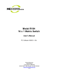
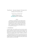
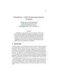
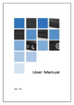
1
Adjustments and Calibrations 5 5 Adjustments and Calibrations 5-2 Belt Tension Adjustment 5-3 Carriage Height Adjustment 5-5 Scan-Axis Belt Tension Adjustment 5-8 Paper-Axis Motor Tension Adjustment 5-10 Printhead Inclination Adjustment 5-12 Printhead Capping Limit Adjustment 5-14 Vertical Capping Position Calibration 5-15 Wiping Position Calibration 5-16 Capping Position Calibration 5-18 Line Sensor Calibration (Side Margin) 5-20 Line Sensor Calibration (Top Margin) 5-22 HP Designjet 8000s Series Printer Service Manual 5-1 Adjustments and Calibrations Adjustments and Calibrations The Printer requires certain adjustments and calibration procedures that must be performed under certain conditions. REMEMBER THAT CERTAIN ADJUSTMENTS AND CALIBRATIONS ARE REQUIRED EVEN IF AN ASSEMBLY HAS BEEN DISASSEMBLED TO GAIN ACCESS TO ANOTHER ASSEMBLY OR COMPONENT. Adjustments refer to procedures that require physical mechanical fine tuning of the different components in the Printer. Calibrations refer to procedures that require entering values through the Front Panel in order to fine tune the components in the Printer. All calibration procedures that need to be done after replacing a Printhead are contained in Chapter 3. Adjustments 1 Belt Tension Adjustment ⇒ Page 5-3. 2 Carriage Height Adjustment ⇒ Page 5-5. 3 Scan-Axis Belt Tension Adjustment ⇒ Page 5-8. 4 Paper-Axis Motor Tension Adjustment ⇒ Page 5-10. 5 Printhead Inclination Adjustment ⇒ Page 5-12. 6 Printhead Capping Limit Adjustment ⇒ Page 5-14. Calibrations 1 Vertical Capping Position Calibration ⇒ Page 5-15. 2 Wiping Position Calibration ⇒ Page 5-16. 3 Capping Position Calibration ⇒ Page 5-18. 4 Side Margin Position Calibration ⇒ Page 5-20. 5 Top Margin Position Calibration ⇒ Page 5-22. 5-2 HP Designjet 8000s Series Printer Service Manual Adjustments and Calibrations Belt Tension Adjustment This adjustment must be performed whenever: Carriage Assembly is disassembled or replaced. Carriage Belt is disassembled or replaced. Be very careful when handling the Carriage Belt because you could easily cut yourself. Perform the Belt Tension Adjustment as follows: 1 Make sure that the Carriage Belt is correctly installed. Make sure that the Carriage is Uncapped before performing the following steps. Trying to move the Carriage out of the Capping Station while it is still capped will cause damage to the Printheads. 2 Move the Carriage to the left and right side of the Printer several times to make sure that the Carriage Belt does not move vertically on the Tension Pulley. If necessary, adjust the slant of the Tension Pulley by tightening or loosening the screws. Make sure the Belt stays in the center of the Tension Pulley 3 Move the Carriage to the Capping Station. HP Designjet 8000s Series Printer Service Manual 5-3 Adjustments and Calibrations 4 Using the Push/Pull Gauge, measure the tension in the middle of the Carriage Belt. The tension measured should be between 175 and 200 g. Protection Block Carriage Belt Push/Pull Gauge In order not to damage the Carriage Belt, please use a protection block between the Push/Pull gauge and the Belt. 5 If the tension is below 175 g, then you must tighten the Tension Pulley screws. If the tension is above 200 g, then you must loosen the Tension Pulley screws. Tension Pulley Screws 5-4 HP Designjet 8000s Series Printer Service Manual Adjustments and Calibrations Carriage Height Adjustment This adjustment must be performed whenever: Carriage Assembly is disassembled or replaced. Center Platen is disassembled or replaced. For this adjustment, you will need the Carriage Height Adjustment Tools. Perform the Carriage Height Adjustment as follows: Make sure that the Carriage is Uncapped before performing the following steps. Trying to move the Carriage out of the Capping Station while it is still capped will cause damage to the Printheads. Before starting the adjustment, make sure that the Media Lever is set to the lower (normal) position. 1 Before starting, make sure that the Printhead Height Levers are in the upper position (so that the Printhead height is actually in the lower position). 2 Manually switch On the Heater and set the temperature to 40oC. 3 Move the Carriage Assembly to the middle of the Center Platen. HP Designjet 8000s Series Printer Service Manual 5-5 Adjustments and Calibrations 4 Identify the different steps of the Carriage Height Adjustment Tools. NO GO GO GO GO GO Target height is 8.1 mm 5 Insert the Carriage Height Adjustment Tools under the Carriage (on both sides). Check that the GO steps of the tool can be inserted under the Carriage Assembly. Slots in the Carriage indicate where the tools should be inserted 6 If the Go steps cannot be inserted or the NO GO step is inserted under the Carriage, the you will need to adjust the Carriage as explained in the following steps. 7 Open the Printhead Cover. 5-6 HP Designjet 8000s Series Printer Service Manual Adjustments and Calibrations 8 Loosen the four screws that secure the Carriage base to the main Carriage Assembly. 9 Place the Carriage Height Adjustment Tools under the Carriage so that the edge of the Carriage is resting on one of the GO steps (ideally on the 3rd step from the front). Slots in the Carriage indicate where the tools should be inserted 10 With the Carriage Height Tools still in position, tighten the four screws that secure the Carriage base to the main Carriage Assembly. 11 Remove the Carriage Height Tools from the Carriage base. 12 Insert the Carriage Height Tools again to check that the GO steps of the tool can be inserted under the Carriage. HP Designjet 8000s Series Printer Service Manual 5-7 Adjustments and Calibrations Scan-Axis Belt Tension Adjustment This adjustment must be performed whenever: Scan-Axis Motor is disassembled or replaced. Scan-Axis Belt is disassembled or replaced. Perform the Scan-Axis Belt Tension Adjustment as follows: 1 Make sure that the Scan-Axis Motor and Belt are correctly installed. 2 Loosen four screws that secure the Scan-Axis Motor Bracket to the Printer. 3 Hook the Push/Pull Gauge onto the Scan-Axis Motor Bracket and tension the Scan-Axis Belt to a force of 41.0 N ±2.0 N (4.18 kgf ±0.2 kgf). Hook the Push/Pull Gauge onto this hole 5-8 HP Designjet 8000s Series Printer Service Manual Adjustments and Calibrations 4 While tensioning the Scan-Axis Belt, tighten the four screws that you loosened in step 2. HP Designjet 8000s Series Printer Service Manual 5-9 Adjustments and Calibrations Paper-Axis Motor Tension Adjustment This adjustment must be performed whenever: Paper-Axis Motor is disassembled or replaced. Paper-Axis Gear is disassembled or replaced. Perform the Scan-Axis Belt Tension Adjustment as follows: 1 Make sure that the Paper-Axis Motor and Gear are correctly installed. 2 Loosen slightly the two screws that secure the Paper-Axis Motor to the Printer. 3 Hook the Push/Pull Gauge onto the Paper-Axis Motor Bracket and tension the Motor to a force of 5.0 N (0.51 kgf) in the direction shown by red arrow. Hook the Push/Pull Gauge onto this slot 5-10 HP Designjet 8000s Series Printer Service Manual Adjustments and Calibrations 4 While tensioning the Paper-Axis Motor, tighten the two screws that you loosened in step 2. 5 Confirm that the Paper-Axis Motor and the Gear are engaged securely by manually rotating the Gear. HP Designjet 8000s Series Printer Service Manual 5-11 Adjustments and Calibrations Printhead Inclination Adjustment In order to check the slant of the Printhead, you can print the Check Slant pattern in the Maintenance Menu. If the printhead is slanted, you will need to perform the Printhead Inclination Adjustment as follows: Printhead 1 Disconnect the Printhead Connector from the Printhead that requires the adjustment. 2 Loosen three screws that secure the Printhead Slot Assembly to the Carriage. 3 Insert the Head Position Adjustment Tool into the positioning hole and tighten the three screws loosened in step 2. Head Position Adjustment Tool 4 Remove the Head Position Adjustment Tool and reconnect the Printhead Connector. 5 Enter into the Maintenance Mode ⇒ Page 4-6. 5-12 HP Designjet 8000s Series Printer Service Manual Adjustments and Calibrations 6 Print the "Check Slant" pattern and check the slant of the Printhead. Error Margin Overlapping Sections Error Margin Overlapping Sections Correct Incorrect 7 If the Check Slant pattern still shows slant, then loosen very slightly the three screws that secure the Printhead Slot Assembly, and manually adjust the slant. HP Designjet 8000s Series Printer Service Manual 5-13 Adjustments and Calibrations Printhead Capping Limit Adjustment This adjustment is necessary in order to stop the Capping Units from pushing against the Printheads too much. This adjustment must be performed whenever: Capping Station is disassembled or replaced. Perform the Printhead Capping Limit Adjustment as follows: 1 Make sure that the Capping Station is correctly installed. 2 Uncap the Carriage Assembly ⇒ Page 4-10. 3 Make sure that the Printhead Height Levers is in the lower position (so that Printhead height is actually in the upper position). 4 Loosen the screw which secures each Capping Limit Plate to the Capping Station. 5 Lower each Limit Plate until it is 0.2 mm above the Ledge on the Carriage. Screw Ledge Limit Plate 6 Tighten the screws that secure the Plates. 5-14 HP Designjet 8000s Series Printer Service Manual Adjustments and Calibrations Vertical Capping Position Calibration This adjustment must be performed whenever: Capping Station is disassembled or replaced Capping Station Lever is disassembled or replaced. Perform the Vertical Capping Position Adjustment as follows: 1 Enter into the Maintenance Mode ⇒ Page 4-6. 2 Enter into the Adjust menu and select "Cap Up/Down Pos" in order to move the capping reference line between the limits shown below. Reference Line Limits HP Designjet 8000s Series Printer Service Manual 5-15 Adjustments and Calibrations Wiping Position Calibration This calibration must be performed whenever: Wiping Station is disassembled or replaced. Perform the Wiping Position Calibration as follows: 1 Enter into the Maintenance Mode ⇒ Page 4-6. 2 Move the Carriage Assembly to the Wiping Position ⇒ Page 4-27. 3 Enter into the "Wipe Position" Menu ⇒ Page 4-26. # WIPE POSITION > +0.0 mm This adjustment must be performed when the Carriage is in the Wiping Position. Do NOT move the Carriage when the Wiper Blade is raised as this could damage the Printheads. 4 Check that the center of the first Printhead (starting from the right) is aligned with the Adjustment Hole in the Wiping Station. Printhead Adjustment Hole 5 If the center of the Printhead is not aligned with the Adjustment Hole in the Wiping Station, you will need to visually estimate the deviation between the two points. Measure deviation 6 Enter the deviation measured using the S and T keys to change the digits and the W and X keys to select the digits. If the Printhead is on the right side of the Adjustment Hole, then enter a + value, and if the Printhead is on 5-16 HP Designjet 8000s Series Printer Service Manual Adjustments and Calibrations the left side of the Adjustment Hole, then enter a - value. # WIPE POSITION * -0.5 mm + Value - Value 7 Press the OK key once you have entered the deviation value. 8 Check again that the center of the Printhead is aligned with the Adjustment Hole. If they are still not aligned, then repeat the procedure from step 5. HP Designjet 8000s Series Printer Service Manual 5-17 Adjustments and Calibrations Capping Position Calibration This calibration must be performed whenever: Capping Station is disassembled or replaced. Capping Unit is disassembled or replaced. Perform the Capping Position Calibration as follows: 1 Enter into the Maintenance Mode ⇒ Page 4-6. 2 Move the Carriage Assembly to the Capping Station (if not already at the Capping Station) ⇒ Page 4-27. 3 If the Printheads are capped, uncap them ⇒ Page 4-10. 4 Enter into the "Cap Position" Menu ⇒ Page 4-26. # CAP POSITION > +0.0 mm This adjustment must be performed when the Printheads have been uncapped. Do NOT move the Carriage when the Printheads are capped as this could damage the Printheads. 5 Visually check that the center of the Capping Units are aligned with the center of the Printheads. Printhead Capping Unit 6 If the center of the Capping Units are not aligned with the center of the Printheads, you will need to visually estimate the deviation between the Capping Units and the Printheads. Measure deviation 5-18 HP Designjet 8000s Series Printer Service Manual Adjustments and Calibrations 7 Enter the deviation measured using the S and T keys to change the digits and the W and X keys to select the digits. If the Printheads are on the right side of the Capping Units, then enter a + value, and if the Printheads are on the left side of the Capping, then enter a - value. # CAP POSITION * +0.3 mm + Value - Value 8 Press the OK key once you have entered the deviation value. 9 Open the Window and close it again so that the Carriage adjusts itself in relation to the Capping Station. 10 Check again that the center of the Capping Units are aligned with the center of the Printheads. If they are still not aligned, then repeat the procedure from step 6. 11 Once the Capping position is aligned, move the Carriage Assembly to the Home Position ⇒ Page 4-27 or power Off and On the Printer. HP Designjet 8000s Series Printer Service Manual 5-19 Adjustments and Calibrations Line Sensor Calibration (Side Margin) This calibration is used to ensure the correct position of the Line Sensor versus the Black Printhead in the Scan-Axis. This calibration must be performed whenever: Line Sensor is disassembled or replaced. Black Printhead is removed or replaced. Perform the Side Margin Position Calibration as follows: 1 When the "Printer Ready" message appears on the Front Panel, press the Online key to take the printer offline. PRINTER READY ROLL: 64/PAPER 2 When the following screen is displayed on the Front Panel, press the Shift key twice. SINK WMEDIA MEDIA REGT M.ADVX 3 When the following screen is displayed on the Front Panel, Press the to enter into the Adjust menu. SPRINTER WADJUST W key SETUPT HEATERX 4 In the Adjust menu, scroll to "Test Prints" and press the OK key. # TEST PRINTS > NOZZLE PRINT 5 In the Test Prints submenu, scroll to "LS Adj Print" and press the OK key. # TEST PRINTS * LS ADJ PRINT 6 Press the OK key to confirm that you want to print the LS Adjust Print. # TEST PRINTS * OK? 5-20 HP Designjet 8000s Series Printer Service Manual Adjustments and Calibrations 7 Measure the side margin using a ruler. If the distance measured is more or less than 15 mm, then the side margin value will need to be changed. Media Printing Direction Printed Area Measure this distance 8 In the Adjustment submenu, scroll to "LS Adj Side Val" and press the X key. # LS ADJ SIDE VAL > +0.0 mm 9 Determine the side margin value to be entered by subtracting the distance measured from the specified side margin value of 15 mm. For example, if the distance measured was 17 mm, then you subtract 17 mm from 15 mm and you get a result of +2 mm. If the distance measured was 12 mm, then you subtract 12 mm from 15 mm and you get a result of -3 mm. 10 Enter the side margin value using the and the S and T keys to change the digits W and X keys to select the digits. # LS ADJ SIDE VAL * +2.0 mm 11 Press the OK key once you have entered the side margin value. HP Designjet 8000s Series Printer Service Manual 5-21 Adjustments and Calibrations Line Sensor Calibration (Top Margin) This calibration is used to ensure the correct position of the Line Sensor versus the Black Printhead in the Media-Axis. This calibration must be performed whenever: Line Sensor is disassembled or replaced. Black Printhead is removed or replaced. Perform the Top Margin Position Calibration as follows: 1 When the "Printer Ready" message appears on the Front Panel, press the Online key to take the printer offline. PRINTER READY ROLL: 64/PAPER 2 When the following screen is displayed on the Front Panel, press the Shift key twice. SINK WMEDIA MEDIA REGT M.ADVX 3 When the following screen is displayed on the Front Panel, Press the to enter into the Adjust menu. SPRINTER WADJUST W key SETUPT HEATERX 4 In the Adjust menu, scroll to "Test Prints" and press the OK key. # TEST PRINTS > NOZZLE PRINT 5 In the Test Prints submenu, scroll to "LS Adj Print" and press the OK key. # TEST PRINTS * LS ADJ PRINT 6 Press the OK key to confirm that you want to print the LS Adjust Print. # TEST PRINTS * OK? 5-22 HP Designjet 8000s Series Printer Service Manual Adjustments and Calibrations 7 Measure the top margin using a ruler. If the distance measured is more or less than 15 mm, then the top margin value will need to be changed. Media Printing Direction Printed Area Measure this distance 8 In the Adjustment submenu, scroll to "LS Adj Top Val" and press the X key. # LS ADJ TOP VAL > +0.0 mm 9 Determine the top margin value to be entered by subtracting the distance measured from the specified side margin value of 15 mm. For example, if the distance measured was 18 mm, then you subtract 18 mm from 15 mm and you get a result of +3 mm. If the distance measured was 13 mm, then you subtract 13 mm from 15 mm and you get a result of -2 mm. 10 Enter the top margin value using the and the S and T keys to change the digits W and X keys to select the digits. # LS ADJ TOP VAL * -2.0 mm 11 Press the OK key once you have entered the top margin value. HP Designjet 8000s Series Printer Service Manual 5-23 Adjustments and Calibrations 5-24 HP Designjet 8000s Series Printer Service Manual Print Quality 6 6 Print Quality 6-2 Print Quality Troubleshooting Actions 6-2 Print Quality General Advice 6-2 Troubleshooting Print Quality Problems 6-3 Horizontal Lines Across the Image (Banding) 6-3 Images are Blurred 6-4 Bleeding, Repelling or Mottling Problems 6-4 Image is Completely Blank or Faded 6-4 Output Only Contains a Partial Print 6-5 The Printer Area is Stained 6-5 Part of Image is Missing at the Start of the Print 6-5 Print Quality is not Improved After Printhead Recovery 6-5 How to Check for Permanent Nozzles Out in a Printhead 6-6 HP Designjet 8000s Series Printer Service Manual 6-1 Print Quality Print Quality Print Quality Troubleshooting Actions For some Print Quality problems, a Call Agent can try and troubleshoot the Printer by requesting the Customer to perform certain actions. Using this process, most problems can be resolved without the need of an on-site visit. When faced with a Print Quality problem, perform the following actions in order to resolve the problem: 1 Printer Configuration: Check that the media type selected in the Front Panel is the same as the media type loaded into the Printer. Make sure that the correct adjustments have been made for each media. 2 Check for any Printhead nozzles out and if necessary perform the Printhead Recovery procedure. 3 Media: Select the correct media type through the front panel when loading it. Make sure that HP or HP-approved media is being used. 4 Check if the latest version of the firmware is installed. If not, install the latest firmware revision. 5 For further information, refer directly to the Troubleshooting section that covers the different Print Quality problems. Print Quality General Advice 1 Performing the Daily Maintenance ensures that the Printheads stay in a good condition and the nozzles don’t get blocked. 2 Make sure that the media type selected in the Front Panel is the same as the media type loaded into the Printer. 3 Roll media usually gives better Print Quality than a single sheet of the same type of media. 4 The most appropriate print quality settings must be used for the current purpose. 5 Check that the environmental conditions (temperature, humidity) are within the temperature/humidity range as specified for the Printer (refer to the User’s Guide for further information). 6 Remember that certain print quality problems can be solved by: Performing the Printhead Recovery procedure. Adjusting the Media Advance. 6-2 HP Designjet 8000s Series Printer Service Manual Print Quality Troubleshooting Print Quality Problems Horizontal Lines Across the Image (Banding) Description of problem When you look at the image you have printed, there are horizontal lines across the image. Shown below is an example of what you might see if you have this problem: Corrective Action 1 Check that the appropriate print quality settings are being used and reprint the image. 2 Check for any Printhead nozzles out and if necessary perform the Normal Printhead Recovery procedure. 3 Change the setting of the Media Pressure Lever. 4 Perform the Media Advance adjustment on the media that is currently being used ⇒ Refer to the User’s Guide. 5 Check the temperature of the Heaters to make sure that they are not set too high. If necessary, lower the temperature of the Heaters and reprint the image. 6 Print the Nozzle Check Pattern (⇒ Page 4-23) to verify if any Printhead Nozzle are missing. If any missing nozzles cannot be recovered, the failing Printhead may need to be replaced. HP Designjet 8000s Series Printer Service Manual 6-3 Print Quality Images are Blurred Description of problem This problem is often caused by incorrect adjustment of the Bi-directional print position causing the image or text to look blurred. Corrective Action 1 Use the Printer in an environment that is less humid. 2 Make sure that the media type selected in the Front Panel is the same as the media type loaded into the Printer. 3 Make sure that the Carriage Height is appropriate for the media loaded (lower the carriage if necessary). 4 Perform the daily Maintenance tasks. 5 Perform the Printhead Recovery procedure. 6 Check that the environmental conditions (temperature, humidity) are within the temperature/humidity range as specified for the Printer. 7 Check that the temperature of the Heaters are not set too low or too high. 8 Perform the Bi-Directional Print Position Correction. Bleeding, Repelling or Mottling Problems Description of problem The problems can be described as follows: Ink Bleeding can spoil the sharpness of the image and cause the text to be blurred. Ink Repelling can cause the lines to be dotty or uneven. Ink Mottling can cause dark lines in high density prints. Corrective Action 1 Try printing using a higher quality print mode. 2 Check the temperature of the Heaters to make sure that they are not set too high. If necessary, lower the temperature of the Heaters and reprint the image. Image is Completely Blank or Faded Corrective Action 1 There might be a problem between the Printer and Computer. Check the cable between the computer and the Printer to make sure it is not damaged and is connected correctly. 2 Check the date file that was sent to print. 3 Make sure that the media type selected in the Front Panel is the same as the media type loaded into the Printer. 4 Check that the room temperature is higher than 15oC and make sure that you leave the Printer to warm up sufficiently. 6-4 HP Designjet 8000s Series Printer Service Manual Print Quality Output Only Contains a Partial Print Corrective Action 1 There might be a problem between the Printer and Computer. Check the cable between the computer and the Printer to make sure it is not damaged and is connected correctly. 2 There might be foreign objects attached to the Printhead. Perform the Printhead Recovery procedure and reprint the image. 3 If cleaning the Printheads does NOT solve the problem, then the nozzles might be blocked. Perform the Wash Printheads procedure (refer to the User’s Guide) and reprint image. The Printer Area is Stained Corrective Action 1 Check if the leading edge of the media is curled. If it is curled, cut off the leading edge before printing. 2 Check if the media is wrinkled. If it is wrinkled, advance the media and cut off the part of the media that is wrinkled. 3 Make sure that the media type selected in the Front Panel is the same as the media type loaded into the Printer. 4 Make sure that the Center Platen is not stained with ink since this could be transferred to the printed image. Part of Image is Missing at the Start of the Print Corrective Action 1 There might be a problem between the Printer and Computer. Check the cable between the computer and the Printer to make sure it is not damaged and is connected correctly. 2 Make sure that the environmental conditions (temperature, humidity) are within the temperature/humidity range as specified for the Printer (refer to the User’s Guide for further information). Print Quality is not Improved After Printhead Recovery Corrective Action 1 Perform the Daily Maintenance procedure (⇒ Page 9-3). 2 Repeat the Printhead Recovery procedure (⇒ Page 9-12) and reprint the image. 3 Print the Nozzle Check pattern and check if there any nozzles missing. If there are several nozzles missing and the Printhead Recovery procedure has not improved the print quality, then it might be necessary to replace the failing Printhead (for more information, refer to Page 6-1). HP Designjet 8000s Series Printer Service Manual 6-5 Print Quality How to Check for Permanent Nozzles Out in a Printhead If a Printhead has more than one permanently out nozzle, the Printhead must be replaced. Nozzles Out Nozzles can become blocked, causing nozzles to fail and not fire ink. When this happens we say that the nozzle(s) are ’out’. There is a procedure we can use to unblock the nozzles that are out which involves firing more ink than usual to clear the blockage and therefor ‘recover’ the printhead. You can choose between a ‘Normal’ or a ‘Strong’ recovery. For further information on performing the Printhead Recovery procedure, refer to Page 9-12. Printhead Nozzles Check The ‘Printhead Nozzle Check’ can determine whether the nozzles are out. Part of the printhead nozzle check is shown below, (the other part of the printout can be ignored for this particular issue). The diagonal lines show the status of each nozzle. If a line is out of sequence it means the nozzle is misdirected; if the line is missing it means a particular nozzle is out, or is substantially misdirected. For further information on performing the Printhead Recovery procedure, refer to Page 9-11. One nozzle out won’t impact the image quality because the technology is in place to hide small imperfections like that. The Printhead Nozzle Check shown here is of a healthy printhead, all lines are present and they are all in sequence. However if when you perform the ‘Printhead Nozzle Check’ and you get results similar to the one shown below (the nozzles that are out are shown in the circles), it could mean that they are out or permanently out. If a printhead has more than one permanently out nozzle it must be replaced, but only after you’ve made sure that the nozzles cannot be recovered. Follow the procedure on the next page to find out if the printhead you have has permanently out nozzles. 6-6 HP Designjet 8000s Series Printer Service Manual Print Quality HP Designjet 8000s Series Printer Service Manual 6-7 Print Quality 6-8 HP Designjet 8000s Series Printer Service Manual