1
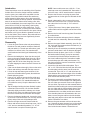
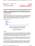
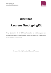
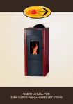
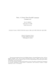
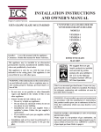
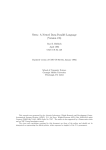
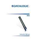
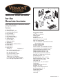
O
M
N
E
C
K
Rebuild Instructions
for the
Resolute Acclaim
H
L
H
J
B
D
K
I
F
G
A
Please read through these instructions before beginning the procedure.
Contents
A. Bottom Plate, 1
B. Inner Side Plate, Left, 1
C. Inner Side Plate, Right, 1
D. Left End Plate, 1
E. Right End Plate, 1
F. Left Shoulder Plate, 1
G. Right Shoulder Plate, 1
H. Sealing Plate, 2
I. Left Arch Brick, 1
J. Right Arch Brick, 1
K. Side Brick, 2
L. Brick Retainer, Stainless Steel, 1
M. Rear Grate, 1
N. Front Grate, 1
O. Back Plate, 1
Tie Rod, 4
Flat Washer, 2
Nut, 1/4-20 Hex Hd Flex Lock, 4
CS 1/4-20 x 1 Blk Hex Hd, 2
Nut, Hex Hd 1/4-20 Pin
CS, Hex Hd 1/4-20 x 5/8 ss
Washer, Flat 1/4 #316 ss
Tubes 11oz. V.C. Cement, 3
5’, 6” Gasket, 5/16” Med. Fiberglass
9 oz. Can High-Temperature Paint, 1
CAR166
Fig. 1 Carton contents.
Suggested Tools
CAR166
drop cloth, 8’ x 8’ (min.)
Rebuild Resolute Acclaim
safety goggles
contents
11/04
putty knife
needle nose pliers, 6”
wire brush 1¹⁄₂” x 6”, 13 overall
shop vac w/attachments
7/16”, 1/2” and 9/16” combination wrenches
(box and open end)
3/8” drive ratchet handle
3/8” drive extension, 6”
wrench, socket, 7/16” deepwell, 3/8” drive
wrench, socket, 9/16” deepwell, 3/8” drive
common flat blade screwdriver 6” long
Phillips screwdriver #3 tip, 8” long
Phillips screwdriver #2 tip, 6” long
hex key (allen) wrench 5/32” and 1/8”
drop light a.c. 40-60 watt, 15’-25’ cord
pair locking pliers 6” - 10”
ball peen hammer, 12 oz. or 16 oz.
hammer, brass face 12 oz. or 16 oz.
rubber mallet 4 lb. dead blow
cold chisel, 3/8”
punch/drive pin, 1/8”, 3/8” and 1/4”
caulking gun
rolling head pry bar, 1/2” x 15”
pinch bar, 1/2” x 15”
sponge or water absorbent cloth
pair cutting shears, 6” - 8”
Repair/rebuild stand
measuring tape
clean rags
2000009 8/08 Rev. 3
Introduction
These instructions cover the rebuilding of the Resolute
Acclaim Stove. Since the design has been modified
over the years, your rebuilt stove may differ from the
original. Current and rebuilt models have stationary
grates instead of sliding grates. Also, they have an air
control which includes a “start-up position” which allows
extra air to enter the firebox when starting a fire. After
the fire is established, the normal range for the air valve
control is from full left (for long-lasting, slow burning
fires) to the centerpoint for faster, hotter fires. To use
the revised valve control, you swing the control handle
to the right until you meet resistance, then press it down
and further to the right to allow the greatest amount of
air into the firebox. Note, however, that continued burning at the highest firing rates can significantly shorten
the life of the inner castings.
Disassembly
1. Lift out the grate. Remove the ash pan and dump
the ashes in a safe container outdoors. Wash the
ash pan and dry it. The ash pan will make a good
container for screws, bolts, nuts, washers and
small hardware items during the disassembly of the
stove.
2. Remove the loading door. Open the door and pull
down on the spring loaded upper hinge pin. When
the upper hinge pin clears its recess, tilt the door
slightly and lift it off the lower hinge pin. Use care
to avoid chipping the enamel surface. Remove the
andirons.
3. Clean out the firebox thoroughly. Vacuum the entire
firebox and ash drop area with the shop vacuum.
4. Lift out the top and bottom grate sections. If the
stove has moveable shaker grates, discard these.
Retain stationary grates.
5. Using a 7/16” wrench, remove the flue collar and
flue collar extension, (four 1/4-20 x 5/8” hex head
cap screws, and four 1/4” standard flat washers
from within the stove). Keep the fasteners for reassembly.
6. Tap the wedges holding the lower fireback in place
upward and remove them. Lift the lower fireback
assembly slightly and shift it sideways so it clears
the tab on one of the core sides and remove it from
the stove. Discard the lower fireback and wedges.
7. Remove the damper handle stub. Loosen the socket set screw in the stub with a 5/32” hex key wrench
(Allen) and pull the stub off the damper shaft.
8. Remove the right stove end. Reach inside the
firebox and remove the hex head cap screw, 1/4-20
x 3/4” and one standard flat washer, 1/4”. A 7/16”
wrench/socket is required. Discard right end.
2
NOTE: Later model stoves use a 3/8-16 x 1” hex
head cap screw and a standard 3/8” flat washer. If
this is the case, a 9/16” wrench/socket is required.
9. Remove the left stove end using the same tools
and procedure as for the right end. Discard the left
end.
10. Reach underneath the four corners of the stove
bottom and remove the four 1/4-20 hex nuts from
the ends of the four tie rods. (A 7/16” socket is
required.)
11. Tap the perimeter of the top plate upward with a
rubber mallet until the top plate can be lifted off the
stove.
12. Remove the tie rods from the top plate. Discard the
tie rods and nuts.
13. Remove the washer and spacer from the damper
rod and retain for reassembly. Remove the damper
rod.
14. Remove the upper fireback assembly, (two 1/4-20 x
3/4” hex head cap screws and two flat washers.) A
7/16” socket is required.
15. Carefully lift out the secondary combustion package
and set it aside where it will not become damaged.
16. Remove the ash pit plate, (two 1/4-20 x 1” Phillips
flat head machine screws). It may be necessary
to insert the tip of the #2 Phillips screwdriver into
the screw heads and give the screwdriver handle
several sharp raps with a ball peen hammer. Pry
the plate up with the common screwdriver once the
screws are removed.
17. Loosen the right and left shoulder plates. Tap a
3/8” or 1/2” cold chisel into the front joint where the
shoulder plate joins the stove front to break the
cement seal. Tap a 3/8” or 1/2” cold chisel into the
joints between the rear lower edges of the shoulder
plates and the stove bottom and break the cement
seal. Discard the shoulder plates.
18. This step is most easily accomplished by two people to prevent the front and back from falling when
the core sides are removed. Remove the right and
left core sides. Tap each core side outward with the
dead blow mallet breaking the cement seal between
the core sides and the front and back plates. Rock
the core sides back and forth to beak the cement
seal between the core sides and the stove bottom.
If the shoulder plates are still attached to the core
sides, remove the grate rod from the left shoulder
plate and gently tap them loose with the dead blow
mallet. Discard the core sides.
19. Remove the grate actuator rod from the stove bottom. Unscrew the grate actuator loop on the outside
end of the rod and remove the grate actuator rod
from inside the stove bottom. Discard the rod.
2000009
20. Remove the front and back plates from the stove
bottom. Gently rock back and forth until the cement
seal is broken and lift them off the bottom plate.
Discard the back plate. Remove all heat shields
and fasteners.
21. Using the 7/16” wrench/socket, remove the secondary combustion package support plate from inside
the bottom of the back plate, (two 1/4-20 x 1/2” hex
head cap screws). Tap the support plate loose from
the back plate with the dead blow mallet.
22. At this time, inspect the gasket material within and
around the upper fireback/damper assembly. If
deterioration is evident, install new gaskets following the procedures outlined in the Resolute Acclaim
Service Manual.
23. Disassemble the primary air valve. Loosen and remove the 1/4-20 hex lock nut, from inside the stove
bottom. Turn the stove bottom over and remove the
hex head cap screw which secures the air valve,
spring, washer and shaft to the stove bottom (two
7/16” wrenches required). Keep all hardware for
reassembly.
24. Use a 7/16” wrench/socket to remove the ashlip,
(two hex head cap screws, 1/4-20 x 5/8” and two
1/4” flat washer). Retain the hardware.
25. Use a 9/16” socket to remove the stove legs, (four
3/8-16 x 1” hex head cap screws, three 3/8” flat
washers and one damper handle holder).
26. Examine the secondary combustion package assembly. Check the refractory chamber and ramp for
breaks, chips, separations and/or general deterioration. If the refractory chamber and ramp are in good
condition, clean it carefully with negative pressure
from your vacuum cleaner. Do not blow the passages with forced air. If the refractory chamber is in
poor condition, seal it in a plastic bag and dispose
of. Replace with a new one.
27. Examine all castings for cracks, chips, distortion,
etc. Remove all old furnace cements from channels and mating surfaces using the appropriate size
punch/drive pin in the channels and cold chisels
on the flanges and flat mating surfaces. Clean all
channels and mating surfaces with a wire brush
(hand or power).
28. Examine all mechanical linkage parts for distortion,
worn or egg shaped drillings, unusual wear, burrs,
etc. Repair or replace as necessary. Replace any
bent tabs or clips.
2000009
Gasket Locations
Back (inside)
ST832
Fig. 2 Inside vertical edges of back plate to vertical edges
of the upper and lower firebacks
seal. Two pieces 20” each,
ST832
fiberglass, 5/16” diameter.
inside back
11/04
Back (outside)
ST833
Fig. 3 Exterior, channel around flue collar opening, 27”, fiberglass, 5/16” diameter.
ST833
outside back
11/04
3
Assembly
1. Invert the new bottom and place it on your rebuild
stand. Install six hex head cap screws 10-24 x 1/2”
if heat shields will not be used. (Fig. 1)
2. Install the four legs onto the stove bottom with the
four hex head cap screws 3/8”-16 x 1” and three
3/8” flat washers plus one each holder, damper
handle insert on the right rear leg. (Fig. 1)
ST835
Fig. 2 Primary air valve assembly.
ST834
Fig. 1 Bottom assembly.
3. Lift the front of the inverted bottom and slide the old
ashlip into position. Align the holes in the stove bottom with the two drilled andST834
tapped bosses on the
ashlip and attach loosely with two 1/4-20 x 5/8” hex
bottom
head cap screws, and two 1/4” flat washers. Do not
11/04
tighten at this time.
4. Assemble the primary air valve, place the “U” portion of the air valve shaft between and around the
upsets on the air valve casting with the upset on
the valve shaft towards the underside of the ashlip. Place the compression spring on the 1/4-20 x
1¹⁄₄” hex head cap screw, next place the 1/4” x 1”
outside diameter washer on the cap screw. Insert
the cap screw with spring and washer through the
air valve shaft and air valve, and thread it into the
stove bottom until the spring is almost fully compressed. Thread a 1/4-20 hex nut onto the air valve
cap screw from inside the stove bottom and tighten
the screw against the stove bottom. The air valve
is properly adjusted when you feel resistance to
movement of the air valve shaft but the shaft moves
from stop to stop easily. (Fig. 2)
4
5. Turn the stove bottom right side up on your rebuild
stand.
6. Place the stove back on its back and install the
damper rod into the holes on either side. Insert the
longer stepped end first into the right side, shorter
end to the left. (Fig. 3)
ST835
7. Cement the bottom of the new stove back as indicated in Figure 4.primary
Place the air
old package support
plate into position11/04
in the stove back.
Align the holes in the package support plate with
the drilled and tapped holes in the bottom of the
stove back. Secure with two 1/4-20 x 1/2” hex head
cap screws. Press the two gasket tails at the bottom of the stove into place over the lip of support
plate. (Fig. 5)
ST836
Fig. 3 Install damper rod.
ST836
damper rod
11/04
2000009
ST839
Fig. 6 Bottom plate cement locations.
Apply Cement Here
ST837
Fig. 4 Cement bottom plate.
ST839
bottom plate cement
11/04
ST837
cement bottom
11/04
ST840
Fig. 7 Top plate cement locations.
ST838
Fig. 5 Install package support.
8. Carefully place the secondary combustion package
into the recess in the back. Be sure to position the
package with the ST838
ramp opening facing down and
toward the front. package support
9. Place the old upper
fireback/damper assembly into
11/04
position on the front gasketed flanges of the stove
back. Align the semicircle cutouts on the sides of
the upper fireback assembly with the drilled and
tapped holes in the front flanges of the stove back.
Secure loosely with 2 each 1/4” flat washers. Do
not tighten the cap screws at this time.
10. Install the two sealing plates, rib side inward, onto
the back over the secondary combustion package
using a 1/4-20 x 5/8” stainless steel hex screw and
1/4” flat stainless steel washer for each.
11. Cement the channels in the stove bottom as indicated in Figure 6.
12. Cement the channels in the underside of the top
plate as indicated in Figure 7.
2000009
13. Place the assembled stove back into its cemented
channel in the stove bottom.
14. Insert the four tieST840
rods through the holes in the bottop plate
cement
tom plate. The longer
threaded
end goes through
the bottom.
11/04
15. Place the assembled stove front into its cemented
channel in the stove bottom and hold it and the
back vertical with a wood bridge. (Fig. 8)
27"
10"
19"
6"
ST841
Fig. 8 Wood bridge dimensions.
16. Cement the channels in the inner side plates as
shown in Figure 9. Place the bottom of each inner
ST841 in the stove bottom at
side into its cement channel
wood bridge
a 45° angle and swing the top against the edges
11/04
of the stove back and front insuring the cement
channels in the inner sides encompass the ribs of
the stove back and front. Tie a rope or strap around
the inner sides, back and front plates to hold the assembly together. Remove the wood bridge.
5
22. Install the left stove end and secure it with one 1/420 x 1” hex head cap screw, flat washer and 1/4-20
nut at the clevis in the bottom plate.
Tighten the ashlip bolts.
23. Cement the stove bottom, air manifold and right
inner side at the locations indicated in Figure 10.
Install the right shoulder plate into position.
24. Cement the stove bottom, air manifold and left inner
side at the locations indicated in Figure 11. Install
the left shoulder plate into position.
ST842
Fig. 9 Inner side plate cement locations. Refer also to Figures 10 and 11.
17. Place the cemented stove top into position insuring
ST842
the top edges of the
front, back and inner sides are
side
plate
properly seated into
their
cement channels in the
cement
underside of the stove
top. Rap the corners of the
top plate with a rubber
11/04mallet to ensure a proper
seat.
18. Thread each tie rod up into the tapped hole in the
underside of the top plate. Continue to thread the
tie rods into the stove top as far as you can with
your fingers. As you tighten the tie rods, work in
alternate sequence to opposite corners.
Thread four each 1/4-20 hex nuts on the long
threaded lower ends of the four tie rods and tighten
securely in an alternating sequence.
Remove the strap from the assembly.
19. Push the damper rod all the way over to the left.
Place the 3/8” x 1” spacer on the right end of the
damper rod. Place the 3/8” flat washer onto the
damper rod and push it against the spacer.
20. Install the right stove end. Swing the bottom of the
stove end out from the side of the stove until you
are able to insert the end of the damper rod through
its drilling in the stove end. Swing the stove end
down into its installed position and secure it with
one 1/4-20 x 1” black hex head bolt, flat washer and
1/4-20 nut at the clevis in the bottom plate.
21. Working from the back side of the stove, push or
gently tap the left end of the damper rod as far to
the right side of the stove as it will go. Install the
damper handle stub onto the damper rod as far
as it will go and secure it by tightening the socket
set screw tightly against the flat of the damper rod
with the 5/32” Allen wrench so when the damper is
closed a tight, firm lock position is achieved. Tighten the lock nut on the ramp adjusting set screw.
6
ST844
Fig. 10 Cement locations: right shoulder, inner side.
ST843
Fig. 11ST844
Cement locations: left shoulder, inner side.
25. Cement
the stovecement
bottom and the left and right
shoulder
shoulder plates at the locations indicated in Figure
11/04
12.
Install the ash pit plate. The two cutouts along
the long edge go toward the back of the stove.
Secure with two Phillips flat head machine screws,
1/4-20 x 1”.
26. Install the flue collar and secure with two 1/4-20 x
5/8” hex head cap screws and two 1/4” flat washers. Install the flue collar extension and secure with
two 1/4-20 x 5/8” hex head cap screws and two 1/4”
flat washers.
27. Install the rear and (large) front grates into position
between the shoulders inside the stove.
28. Install the left and right arch bricks. First, set the
bottoms of both arches into position against the
fireback, (ribbed face forward). Then, join the two
ST843
left shoulder cem
11/04
2000009
Break-In Procedure
The new castings just installed in the unit require the
same seasoning process recommended for a new
stove. This entails burning 3-4 small fires and allowing
the stove to cool down between each. Failure to breakin the castings can cause damage to occur.
ST845
Fig. 12 Cement ash pit plate.
29.
30.
31.
32.
33.
by tilting both forward enough together to insert the
stainless steel retainer over the upper ends and
ST841
across the middle joint. Tilt the assembly back to
cement ash pit
rest against the fireback.
Set each side brick11/04
into place. First, insert the rear
edge into a back corner, then swing the forward
edge to the side and up over the shoulder rib.
Install the drop-in andirons and the ash pan. Drop
the andirons into their respective slots in the front
edge of the stationary grate with the cast design on
the andirons facing outward.
Install the loading door. Holding the door in the
vertical position and 75-90 degree in relation to
the stove front, place the lower hinge drilling onto
the adjustable bottom hinge pin. Pull down on
the spring loaded upper hinge pin and maneuver
the top of the door so the spring loaded hinge pin
enters the upper hinge drilling. Close the door and
listen for any metal to metal contact. Check the
upper and lower horizontal alignment of the door
in relation to the stove top and the ash lip. If you
hear metal to metal contact when closing the door
or there is a wide gap at the top, open the door,
pull down on the upper hinge pin, lift the door off
the lower hinge pin with the 1/2” wrench and turn
the hinge pin 360° counterclockwise. This will raise
the door approximately 1/16”. Tighten the hinge pin
and reinstall the door. Close the door and again
listen for metal to metal contact and check alignment. Continue the adjustment process until a good
seal is obtained, alignment is good and no metal to
metal contact is heard.
Paint the stove. Use Castings High Temperature
Stove Paint (black) part number 000-0086, (9 oz.).
Follow the directions printed on the can.
Install the griddle in its proper position in the stove
top.
2000009
7
MHSC
149 Cleveland Drive • Paris, Kentucky 40361
www.mhsc.com