Transcript
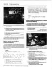
130-20
FUEL INJECTION
NOTE-
" The tests given below are electrical checks only. They
do not check the mechanical operation of the valve. If
the valve is suspected of causingpoor idie, substituting a known good valve is the best way to check fora
mechanical fault.
1 . With engine running, check that ¡die speed control
valve is buzzing.
2. Turn on A/C or shift car finto drive. ¡die should remain
steady or increase slightly.
3. If valve is not buzzing, or if ¡die decreases in step 2,
stop engine and disconnect harness connector from
valve. Check resistance of valve across its terminals.
See Fig. 30 . Test values are listed below.
NOTE -
If you suspect an
intermittent fault, lightly tap the valve
while testing resistance .
Fig . 29. Throttle position sensor terminal identification on M50 engine.
Table g. Throttle Position Sensor Tests
(DME 3.113.3.1)
Test conditions
I Terminals
Harness connector
disconnected, ignition on
13 and ground
in harness
connector
I Test value
15 VDC (approx .)
Harness connector
disconnected, ignition off
1 and 3 at sen- 14 k ohms (approx .)
sor terminals
Throttle plate rotated from ¡die to full
throttle position
1 and 2 at sensor terminals
Variable from 1 - 4 k
ohms (approx .) without interruption
NOTE-
On cars with traction control, do notconfuse the throttle
position sensor on the main throttle body with the throttle position switch on the secondary throttle body,
where applicable .
¡die speed control valve, testing
11250
Fig. 30 . ¡die speed control valve terminal identification .
¡die Speed Control Valve Coil Resistance Values
" M50/S50US engine
Terminals 1 and 2 . . . . . . . . . . . . . . . . . . . 20
t
5 ohms
Terminals 2 and 3 . . . . . . . . . . . . . . . . . . . 20 t 5 ohms
Terminals 1 and 3 . . . . . : . . . . . . . . . . . . .40 t 5 ohms
4. With valve harness connector disconnected, check for
battery voltage at red/white wire in connector with ignition tumed on .
¡die speed is maintained by the ECM through the ¡die speed
control valve. The ¡die control function compensates for engine
load and engine operating conditions . ¡die speed is adaptive
through the ECM and no ¡die speed adjustments can be made .
" If there is no voltage, check wiring between connector and main relay terminal 87 . See Electrical Wiring
Diagrams .
Before testing the valve, confirm that the throttle position
sensor is working correctly.
The idle speed control valve receives positive (+) battery voltage from the main relay.
NOTE-
5. If voltage is presentas described above, check wiring
between ECM and valve. If no wiring faults are found,
check ECM signal to valve.
BOSCH DME M3. 1 AND M3.3.1 COMPONENT TESTS AND REPAIRS
Versión electrónica licenciada a Hernan Fulco / [email protected] / tel: 54(11)4855-3088
Buenos Aires // Argentina