1
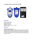
Table of Contents
Safety Precautions…………….……….…………..…………..2
About VAG5053……….………..………………………………..4
1. Applications……………….……….……………………….…..4
2. Available Functions…………….…..…………….……………4
3. Supported Systems……………………………….…………..4
4. Main Features…………………………………….…………...4
5. Appearance and Key Descriptions…………….……………5
Operation Instructions……………….....……………………..6
1. Preparation for Testing…………….………….……………..6
2. Connect the VAG5053………………….…………………….7
3. Diagnosis system…………………..…..…………...…………7
3.1 READ ECU version…………………….…….….…….……9
3.2 Read Fault memory………..……………………..……..9
3.3 ERASE Fault…….…………………….……………….10
3.4 Basic Setting…………….………………………..……10
3.5 READ Measuring value…………………………….…11
3.6 READ indi. value……………………………...………12
3.7 Adaptation………………………….…………………..13
3.8 Code Control unit…………….……………………….…14
3.9 FND Output…………….……………………………..15
3.10 Login procedure…………….…….………….……….15
4. Location of Data Link Connector………………………..….16
5. The use of upgrading software…………………..……...….17
www.uiftech.com
VAG5053
VW/AUDI
Safety Precautions
To avoid personal injury, instrument damage and/or damage to your
vehicle; do not use the VAG5053 before reading this manual.
This manual describes common test procedures used by experienced
service technicians. Many test procedures require precautions to avoid
accidents that can result in personal injury, and/or damage to your vehicle
or test equipment. Always read your vehicle's service manual and follow its
safety precautions before and during any test or service procedure.
ALWAYS observe the following general safety precautions:
z When an engine is running, it produces carbon monoxide, a toxic and
poisonous gas. To prevent serious injury or death from carbon
monoxide poisoning, operate the vehicle ONLY in a well-ventilated
area.
z To protect your eyes from propelled objects as well as hot or caustic
liquids, always wear approved safety eye protection.
z When an engine is running, many parts (such as the coolant fan,
pulleys, fan belt etc.) turn at high speed. To avoid serious injury,
always be aware of moving parts. Keep a safe distance from these
parts as well as other potentially moving objects.
z Engine parts become very hot when the engine is running. To prevent
severe burns, avoid contact with hot engine parts.
z Before starting an engine for testing or trouble-shooting, make sure
the parking brake is engaged. Put the transmission in park (for
automatic transmission) or neutral (for manual transmission). Block the
drive wheels with suitable blocks.
z Connecting or disconnecting test equipment when the ignition is ON
can damage test equipment and the vehicle's electronic components.
Turn the ignition OFF before connecting the VAG5053 to or
disconnecting the VAG5053 from the vehicle’s Data Link Connector
(DLC).
z To prevent damage to the on-board computer when taking vehicle
electrical measurements, always use a digital multimeter with at least
10meg Ohms of impedance.
z Fuel and battery vapors are highly flammable. To prevent an explosion,
2
VAG5053
z
VW/AUDI
keep all sparks, heated items and open flames away from the battery
and fuel / fuel vapors. DO NOT SMOKE NEAR THE VEHICLE
DUR-ING TESTING.
Don't wear loose clothing or jewelry when working on an engine.
Loose clothing can become caught in the fan, pulleys, belts, etc.
Jewelry is highly conductive, and can cause a severe burn if it makes
contact between a power source and ground.
3
VAG5053
VW/AUDI
1
About VAG5053
1. Applications
VAG5053 is a powerful, affordable handy scanner designed for all VW,
AUDI, SKODA, and SEAT vehicles. It is small in size, robust in design,
competitive in price and easy to use. With only 10% of the cost of a large
special tool, it can nearly do the same work as that of a VAG1551/1552.
This is a stand alone unit; it does not need a laptop computer to operate.
2. Available Functions
z
z
z
z
z
z
z
z
z
z
z
z
z
Control Unit Information
Read Fault Codes
Measuring Blocks
Clear Fault Codes
Basic Setting
Adaptation
Single Reading
Output Tests
Code Module
Login
Service Oil Reset
Code Modes
Dealership Code Set
3. Supported Systems
VAG5053 can support the following systems:
z Engine
z Transmission
z Airbag, etc.
4. Main Features
z
z
z
z
Low price: the price is only about 10% of that for a large special tool
Powerful functions: it can nearly do the same work as that of a
VAG1551/1552
Powered via diagnostic connector, no additional power is needed
Plug and play, ease to use
4
VAG5053
z
VW/AUDI
High reliable and accurate
5. Appearance and Key Descriptions
The appearance of a VAG5053 is as shown in the above figure.
1. LCD screen: 128*64
2. Enter key: confirm selection and enter
3. Esc key:
go back to the previous screens
4. up/down arrows: moves the selection pointer and scrolls up or down
5. LEFT/RIGHT arrows: move cursor.
6. Power button
7. Diagnostic extension cable: OBDII -16PIN
5
VAG5053
VW/AUDI
Operation Instructions
1. Preparation for Testing
The VAG5053 aids in monitoring electronic and emissions-related faults in
your vehicle and retrieving fault codes related to malfunctions in these
systems. Mechanical problems such as low oil level or damaged hoses,
wiring or electrical connectors can cause poor engine performance and
may also cause a “false” fault code. Fix any known mechanical problems
before performing any test. See your vehicle’s service manual or a
mechanic for more information.
Check the following areas before starting any test:
z Check the engine oil, power steering fluid, transmission fluid (if
applicable), engine coolant and other fluids for proper levels. Top off
low fluid levels if needed.
z Make sure the air filter is clean and in good condition. Make sure all
air filter ducts are properly connected. Check the air filter ducts for
holes, rips or cracks.
z Make sure all engine belts are in good condition. Check for cracked,
torn, brittle, loose or missing belts.
z Make sure mechanical linkages to engine sensors (throttle, gearshift
position, transmission, etc.) are secure and properly connected. See
your vehicle’s service manual for locations.
z Check all rubber hoses (radiator) and steel hoses (vacuum/fuel) for
leaks, cracks, blockage or other damage. Make sure all hoses are
routed and connected properly.
z Make sure all spark plugs are clean and in good condition. Check for
damaged, loose, disconnected or missing spark plug wires.
z Make sure the battery terminals are clean and tight. Check for
corrosion or broken connections. Check for proper battery and
charging system voltages.
z Check all electrical wiring and harnesses for proper connection. Make
sure wire insulation is in good condition, and there are no bare wires.
z Make sure the engine is mechanically sound. If needed, perform a
compression check, engine vacuum check, timing check (if
applicable), etc.
6
VAG5053
VW/AUDI
2. Connect the VAG5053
2.1 Turn the ignition off.
2.2 Locate the vehicle's 16-pin Data Link Connector (DLC).
2.3 Connect the VAG5053 cable connector to the vehicle’s DLC. Turn
on the ignition, Press [power button], The VAG5053 will auto start,
the following screen will be displayed.
2.4 Wait a moment, the screen will auto display the main menu:
z
z
[Diagnosis system]: enter the control module selection menu.
[Contrast]: adjust the contrast.
3. Diagnosis system
Select [Diagnosis system] and then press [enter] key. The screen will
display the system selection menu as follow:
7
VAG5053
VW/AUDI
Here let’s take [01. Engine Elec.] for example. Select [01. Engine Elec.],
and press [Enter] key. The screen will display the following message:
After successful communication, the screen will display the ECU version
information as shown in the figure below:
press any key.
Select [01. READ ECU version], and press [Enter] key. The screen will
display the following message:
8
press [Esc] key, VAG5053 will enter the function menu for engine
electronics system:
3. 1 READ ECU version
Select [01.READ ECU version] and then press [Enter] key. The screen will
display the control unit information:
3.2 Read Fault memory
Select [02. RD Fault memory] and then press [Enter] key. If the system has
fault code(s), the screen will display the fault code(s) and descriptions:
As seen on the top right corner, the front digit is the No. of the displayed
fault code, while latter digit is the number of total fault codes.
Press [down] key to read the next page, press [up] key for the previous
page.
1
3.3 ERASE Fault
Select [03. ERASE Fault] and then press [Enter] key. The fault codes will
be erased.
3.4 Basic Setting
Basic Settings mode is very similar to Measuring Blocks. The content of
each display group is the same. The difference between the functions is
that the Control Module may try to perform various calibrations while in
Basic Settings mode.
Warning!
You should refer to the Factory Repair Manual for your particular car
(or some other documented procedure) before "playing" with the
Basic Settings function. Failure to follow the proper procedures can
result in serious damage to the vehicle.
Select [04. Basic Setting] and then press [enter] key. The screen will be
displayed as shown below.
You should input the Channel Number first (from 0-255).
2
You can input the Channel Number with the [up], [down], [left],[right]and
[enter] key:
z [up] and [down] keys: increase or decrease the number.
z [left] and [right] keys: moves the cursor [---] and select the digit.
z [enter] key: confirm and enter.
For example, enter Channel number 001 and press [enter] key, the screen
will display the data stream for data block 001, as shown in the figure
below:
Notes:
Multiple Groups are not permitted in Basic Settings. The data
presented in each Basic Settings Group varies greatly from Control
Module to Control Module and between different models and years.
Some groups are documented in the Factory Repair Manuals, but
many are not.
3.5 READ Measuring value
Select [05. READ Measuring value] and then press [enter] key. The
screen will be displayed as shown below.
3
You should input the Channel Number first (from 0-255).
When the Block number is entered, press [enter]. The screen will be
displayed as shown in the figure:
Here you can press [down] key to switch to the next block, or press [up] to
return to the previous block.
3.6 READ indi. value
Select [06. READ indi. value] and then press [enter] key. The screen will
be displayed as shown below.
4
You should input the Channel Number first (from 0-255).
When the Block number is entered, press [enter]. The screen will be
displayed as shown in the figure:
3.7 Adaptation
The Adaptation function allows you to alter certain values and/or settings in
control modules that support it.
Select [07. Adaptation] and then press [enter] key. The screen will be
displayed as shown below.
You should input the Channel Number first (from 0-255).
5
When the Block number is entered, press [enter]. The screen will be
displayed as shown in the figure:
Here you can press [up] and [down] keys to adjust the adaptation value,
and then press [enter] key to save the adaptation value, or press [esc] key
to cancel the operation and return.
3. 8 Code Control unit
Select [08. Code Control unit] and then press [enter] key. The screen will
be displayed as shown below.
Input the Channel Number and press [enter] key, The screen will display
the control unit information:
6
3.9 FND Output
Select [09. FND Output] and then press [enter] key. The screen will be
displayed as shown below.
The VAG5053 is testing the displayed actuator. Here you can press [up]
key to switch to the next actuator, or press [down] key to cancel the
operation and return.
3.10 Login procedure
The Login Function must be used on some (but not all) Control Modules
before you can Recode or change Adaptation values. On others, it
"enables" certain features like cruise control. Valid Login codes can be
found in the Factory Repair Manual for your car.
Select [10. Login procedure] and then press [enter] key. The screen will be
displayed as shown below.
7
Warning!
Make sure get the correct module code before performing this
function; otherwise the system may be destroyed.
4. Location of Data Link Connector
The OBD-II 16pin connector is as shown in the figure below. For Golf, it is
located on the right side of steering column; For Jetta, it is located in the left
driver room below instrument panel; For Santana, it is located in front of the
gearbox dust cover.
For more detailed information, please refer to the Repair Manual of your
vehicle.
8
The use of upgrading software
Correct installation of updated software is through com cable connecting
the com mouth of the computer. (You don’t need to open the power of the
memo scanner.)
1. visit website ww.memoscan.cn, download the software
2. Run UIF-ISP,. there will be the interface as follows
3.
Select the com port.
1
4.
Press “Open File” button, select the file for update(expand: .uif)
5.
Press “update”, open the power of memo scanner, there will be the
interface as follows. The Memo scanner is trying to connect with PC.
2
5-1. The blow interface will appear if the connection is success.
5-2. If the connection is fail, this time requests to close the power of memo
scanner and check whether the connection and the choice of COM
mouth are right or not.
3
6.
Connection succeed, upgrading starts.
6-1. If the below interface appears in the process of upgrading, that’s to say
the communications failures, this time requests to close the procedures
and re-run the programmer
4
7.
update successful
7-1. If the below interface appears, that’s to say the upgrading failure. This
time requests to close the power of memo scanner and back to step 1 to
re-upgrading .
5