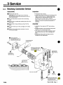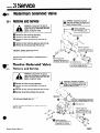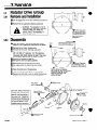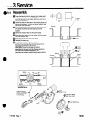
1
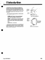
Service
Manual
70E Roll Clamp
P/N 667442
cascade@
corporation
P.O. Box 20187
l
Portland,
Oregon 97220
l
(5031666-l
511
Contents
Page
Number
13-1
13-2
INTRODUCTION Section 0 .................
PERIODIC MAINTENANCE Section 1. .......
TROUBLESHOOTING Section 2
General Procedures ......................
13-3
Schematics. ............................
13-5
13-6
Clamp Circuit ...........................
.13-9
Swing Circuit ..........................
.13-13
Rotate Circuit ..........................
SERVICE Section 3
13-16
Clamp Removal .........................
13-17
Clamp Arm .............................
13-19
Swing Arm .............................
13-21
Cylinder. ...............................
13-25
Revolving Connection. ....................
13-27
Waterman Solenoid Valve .................
13-27
Racine Solenoid Valve. ...................
13-28
Rotator Drive Group. .....................
13-31
Motor. .................................
13-33
Junction Block ...........................
13-34
Frame Assembly. ........................
INSTALLATION Section 4
.13-37
Introduction ............................
13-37
Truck System Requirements ...............
13-38
Hose Reel installation ....................
13-38
Junction Block Installation. ................
13-39
Solenoid Valve Installation. ................
Auxiliary Valve Control Knob Installation ..... 13-40
13-41
Hydraulic Port Identification ...............
13-44
Plumbing the Truck ......................
13-45
Wiring .................................
13-46
Flushing the Hoses ......................
13-46
Attachment Installation ...................
13-48
Attachment Stop Blocks. ..................
13-48
Testing Prior to Operation .................
I
Cascade Corporation
Ring Gear Assembly
reserves the right to alter or improve the specifications
or design configuration
of its products without
notice.
c
Section
0 Introduction
This manual provides the periodic maintenance,
troubleshooting, service procedures and installation instructions for the Cascade 70E Paper Roll Clamp. There
are two basic units: mill unit and converter unit. The mill
unit is equipped with single-stage clamp cylinders and will
handle rolls 30” to 60” in diameter. The converter unit
has two-stage cylinders and will clamp any roll up to 60”
in diameter.
Clamp Arm
The Cascade 70E Paper Roll Clamp is a three function
attachment. The functions are:
Only the clamp arm moves
NOTE:
Mill units can handle
30 to 60 inch rolls only
CLAMP- A Mill unit can clamp rolls between 30
and 60 inches in diameter. A Converter unit can
clamp rolls of any diameter up to 60 inches.
SWING- A clamped load can be positioned side-toside or up and down, depending on how the attachment has been rotated, without affecting clamping
force.
ROTATE-360°,
continuously.
To perform all three functions, the 70E is equipped with
a unique hydraulic system. The system makes it possible
to operate all three functions with only two truck auxiliary
valves in conjunction with a truck-mounted solenoid valve
(supplied with your attachment).
Form 5165 Rev. 0
Swing arm
is pivoted
to the
attachment
faceplate
When the swing
arm is actuated
the clamp arm
moves with it
Both arms move simultaneously
13-1
Section
1 Periodic Maintenance
1.1 100 Hour Maintenance
Every time the lift truck is serviced or every 100 truck
operating hours, whichever comes first, the following
maintenance should be completed.
Cl Check the edge of the contact plates for wear or sharp
nicks that could damage or tear paper rolls. Replace
the contact plates if necessary.
II Check the pressure (see paragraph 2.1-1 on page 13-3)
by performing the pressure test outlined in the Clamp
Circuit Troubleshooting,
page 13-7, and the Swing
Circuit Troubleshooting,
page 13-9.
1.2
500 Hour Maintenance
In addition to the 100 hour maintenance, perform the
following maintenance every 500 truck operating hours.
0 Lubricate the ring gear/bearing
assembly with wheel
bearing grease. Rotate the clamp one full turn during
lubrication.
•I Retorque the mounting hook capscrews using the
torque specifications on pages 13-16 and 13-34.
Cl Remove the plug on the back of the baseplate and
retorque all the ring gear/bearing
assembly capscrews
to 65 - 70 ft.-lb.
0 Remove the plug on the side of the rotator drive gearcase and fill to capacity with Cascade Rotator Drive
Lubricant (part no. C-656300) or Keystone WG-1.
1.3 1000 Hour Maintenance
In addition to the 100 and 500 hour maintenance, perform the following every 1000 truck operating hours.
q Check the pivot point bushings on the cylinders,
arms,
and rotator frame for worn, deeply scratched or
marred inside surfaces. Replace if any of these
symptoms exist. See pages 13-17, 13-19, 13-24, and
13-35.
1.4 2000 Hour Maintenance
In addition to the 100 and 500 hour maintenance, per.
form the following every 2000 truck operating hours.
Cl Replace all pivot point bushings. See pages 13-17,
13-19, 13-24, and 13-35.
13-2
Form 5165 Rev. 0
*
2 Troubleshooting
Section
l
2.1 General Procedures
Please read this section before
you begin troubleshooting.
A
WARNING: Before servicing any hydraulic component, open the arms 1-2", turn the truck off and
relieve all pressure in the system by opening and
closing all auxiliary valves. Be sure you complete
this procedure with the solenoid valve activated.
After completing any service procedures, always test
each function (swing, rotate, and clamp) through 5
complete cycles. First test the clamp empty, to bleed
off any excess air trapped in the system. Then test
each function with a load, to make sure the clamp
operates correctly before returning it to the job.
Truck System Requirements
2.1-1
l
Pressure:
Your truck should supply enough pressure
to adequately handle the heaviest load.
PRESSURE MUST NOT EXCEED 2000 psi.
Volume:
15-20 g.p.m.
Tools Required
2.1-2
In addition to a normal selection of hand tools, you will
need:
l
l
l
l
l
l
l
l
2.1-3
1 No. 6 Straight thread connector fitting (with O-ring).
2 each No. 8 and No. 6 reducers.
1 metal plug (No. 8, 37° flared male) for hose.
2 metal caps (No. 8, 37° flared female) for ports.
2 pressure gauges that are capable of reading
pressures up to 2500 p.s.i.
2 needle shutoff valves, rated at 2500 p.s.i.
1 voltmeter or test light.
1 ohmmeter.
General PressureTest
& Bleed Procedures
For maximum accuracy, you should set one of your
pressure gauges up as indicated in this illustration. The
needle valve and drain line will allow you to bleed off
trapped air in the system before you take your pressure
readings.
Needle
Unless otherwise indicated, you should always use this
pressure gauge, with the needle valve and drain line, for
troubleshooting.
To use the pressure gauge, use the following procedures
to bleed the air from the system before reading your
gauge:
_ Open the arms 1-2".
Female Fitting
NOTE:
Make sure
the arrow points in
this direction.
_ Turn the truck off and relieve any pressure in the system
by opening and closing the truck valves.
-
Install the pressure gauge as indicated in the test
checklist, on the following pages, for each circuit.
Form 5165 Rev. 0
13-3
,
2 Troubleshooting
section
2.1-3 General Pressure Test
& Bleed Procedures (Cont.)
_ Place the drain hose in an empty container.
_ Open the needle valve ½-1 turn, maximum.
WARNING: Before operating the truck,
-
Open the truck valve and power the truck at idle.
-Wait approximately 4-5 seconds and close the needle
valve tightly.
In Container
_ Close the truck auxiliary valve.
-
2.1-4
You are now ready to read the gauge.
Get All The Facts Before You
Begin Working On The Clamp
It is extremely important to gather all the facts regarding
the problem before you begin your service procedures.
The best way to gather the information is to talk with the
operator. Ask for a complete description of the malfunction. The following guidelines will help you decide where
to begin your troubleshooting procedures.
A. Clamp Circuit
Clamp drops roils after they have been gripped.
Clamp will not carry rolls up to the capacity of the
clamp.
l
Clamp arm won’t function properly.
l
Clamp arm drifts, towards swing arm, when in the
horizontal position.
If one of these problems exists, see page 13-6.
l
l
B. Swing Circuit
Swing function operates very slowly.
Swing is in one direction only.
l
Clamp drifts when in ‘bilge’ (horizontal) position.
l
Clamp attempts to do two functions simultaneously.
If one of these problems exists, see page 13-9.
l
l
C. Rotation Circuit
* Clamp swings when it is supposed to rotate.
l
Clamp won’t rotate.
l
Clamp will not rotate rolls up to the capacity of the
clamp.
l
Clamp will rotate in one direction but not the other,
If one of these problems exists, see page 13-13.
13-4
Form 5165 Rev. 0
.
I
l
Section
2 Troubleshooting
2.2 Schematics
2.2-1
Plumbing
Junction
Block
\
Junction
,Block
.eft-Hand/
Hose Reel
Hose Keel
Rotate/Swing
Auxiliary
Valve
‘Clamp
‘Auxiliarv
Valve
2.2-2
NOTE: Auxiliarv
valve ports and
I hose reel ports
may be reversed
I from those shown.
1
I
I
Hydraulic
I II
Clamp m
Form 5165
Rev. 1
13-5
Section
2 Troubleshooting
2.3
Clamp Circuit
A
WARNING: Before servicing any hydraulic component, open the arms 1-2”, turn the truck off and
relieve all pressure in the system by opening and
closing all auxiliary valves. Be sure you complete
this procedure with the solenoid valve activated.
After completing any service procedures, always test
each function (swing, rotate, and clamp) through 5
complete cycles. First test the clamp empty, to bleed
off any excess air trapped in the system. Then test
each function with a load, to make sure the clamp
operates correctly before returning it to the job.
2.3-1
Clamp Circuit Plumbing
CLAMP - CLOSE
CLAMP - OPEN
PRESSURE
PRESSURE
-
-
RETURN
Auxiliary
Valve
Rotate/Swinp
W
Auxiliary
Valve
‘Auxiliarv
Valve
Cvlinder
23.2
Clamp Circuit Troubleshooting
There are four potential problem areas that could affect
clamping force.
l
l
l
l
Insufficient hydraulic pressure.
External leaks.
Malfunctioning cartridge check valves.
Worn or defective cylinder seals.
To isolate the problem area, complete the following check
list in the exact sequence indicated.
13-6
Cartridge Checks In
Revolving Connection
Truck
/
Svstem
Possible Leak Points
Form 5165 Rev. 0
.
2 Troubleshooting
I Section
2.3-2
Clamp CircuitTroubleshooting
(Cont.)
Close Clamp Arms
1. Pressure Test
_ Open the arms 1-2".
- Install your pressure gauge on one of the ‘clamp’
cylinder test ports.
_ Set up the pressure test described in paragraph 2.1-3.
To perform this test, move the control handle to the
CLAMP position. The initial reading should be the
truck’s system pressure (a 100 psi loss is OK).
If the gauge does not register the truck system
pressure, check the pressure being delivered by the
truck pump as outlined in your truck service manual.
Adjust and repair as necessary. Following the adjustment recheck the pressure at the ‘clamp’ cylinder test
port.
If a gradual pressure loss continues (after the 100 psi
loss) this indicates a problem in the clamp components. Proceed with the troubleshooting checklist.
Test
Port
Pressure
Gauge
If the pressure reading is not within 100 psi of the
truck system pressure, AND there is no gradual
Pressure loss, your problem may not be hydraulic, but
may be related to the application of the clamp. In this
case, call Cascade’s Service Department at
800-547-5266 (toll-free), or in Oregon, 666-1511.
2. External Leaks
_ Refer to the diagrams on the preceding page and
check for all areas that could have external leaks.
_ Repair as necessary and carefully operate the clamp
with a load to determine if the problem has been
solved.
A
L
WARNING: Stay clear of the load while
testing, and do not raise the roll more
than 3 inches off the floor.
3. Cartridge Check Valve Test
_ Open the arms 1-2".
_ Relieve any pressure in the system by opening and
closing the truck valves, then turn the truck off.
_ Remove both of the inside hoses (pressure lines) from
the clamp cylinders. Plug one hose with a No. 8 metal
plug.
_ Set up the pressure test described in paragraph 2.1-3.
To perform the test, move the control handle to the
CLAMP position. The initial reading should be the
truck’s system pressure (a 100 psi loss is OK).
mm
‘l-,9
CTThis
Hose
bi
Valve
is Closed
If there is a gradual pressure loss (after the 100 psi
loss), once the truck valve is closed, one of the following problems is responsible:
a. Check valve cartridge is defective.
b. Cartridge seals are severely damaged.
c. Revolving valve body is damaged internally.
_ Repeat this test on the capped hose, to check the
other cartridge and cartridge seals.
_ Replace cartridge, cartridge seals, or valve body if
necessary.
Form 5165
Rev. 0
13-7
Section
2-3-2
2 Troubleshooting
Clamp Circuit Troubleshooting
(Cont.)
4. Cylinder High Pressure Seal Test
IMPORTANT: In order to accurately check the cylinder
seals, you must have completed the prior steps in this
check list.
_ Open the arms 1-2”.
- Install a pressure gauge in the test port on one of the
cylinders.
_ Set up the pressure test described in paragraph 2.1-3.
To perform the test, move the control handle to the
CLAMP POSITION. The initial reading should be the
truck’s system pressure (a 100 psi loss is OK).
If there is a gradual pressure loss (after the 100 psi
loss), once the truck valve is closed, replace the
cylinder seals (see page 13-21).
_ Repeat the test on the other cylinder test port.
_ Carefully operate the clamp with a maximum load (in
the vertical position) to determine if the problem has
been solved.
A
WARNING: Stay clear of the load
while testing, and do not raise the roll
more than 3 inches off the floor.
5. Cylinder Low Pressure Seal Test
_ Open the arms 1-2".
_
Remove both of the outside hoses (return lines) from
the clamp cylinders. Plug the hoses with No. 6 metal
plugs.
-
Install a needle valve (attached to a length of hose)
into the open port on each clamp cylinder. Close the
needle valve tightly.
_
Rotate the clamp to the horizontal
clamp arm on top.
position with the
Needle Valve
If the clamp arm drifts down, then both cylinders have
damaged seals.
If no drift occurs, one of the cylinders MAY have
defective seals. Perform the following to determine if
one of the clamp cylinders needs new seals:
_ Slightly open the needle valve
If the clamp arm drifts down,
defective seals.
If no drift occurs then cylinder
- Repeat this needle valve test
If the clamp arm drifts down,
defective seals.
If no drift occurs then cylinder
13-8
Drifts
Down
on cylinder A.
then cylinder B has
B seals are OK.
on cylinder B.
then cylinder A has
A seals are OK.
_ Carefully operate the clamp with a maximum load (in
the vertical position) to determine if the problem has
been solved.
A
c’amp Arm
WARNING: Stay clear of the load
while testing, and do not raise the roll
more than 3 inches off the floor.
‘/
6.
If you have carefully and accurately completed this
check list, and you still have not solved the problem,
DO NOT PROCEED! Please call one of our service
representatives
at 800-547-5266 (toll free), or in Oregon,
666-l 511. Our Service Department is open from 10:00
a.m. to 8:00 p.m. Eastern Time.
Call Cascade’s Service
Department at 80@547=5266
In Oregon 6661511
Form 5165 Rev.0
.
.
Section
2.4
2 Troubleshooting
SwingCircuit
A
7
WARNING: Before servicing any hydraulic component, open the arms 1-2”, turn the truck off and
relieve all pressure in the system by opening and
closing all auxiliary valves. Be sure you complete
this procedure with the solenoid valve activated.
After completing any service procedures, always test
each function (swing, rotate, and clamp) through 5
complete cycles. First test the clamp empty, to bleed
off any excess air trapped in the system. Then test
each function with a load, to make sure the clamp
operates correctly before returning it to the job.
2.4-1
Swing Circuit Plumbing
Left-Hand
Hose Reel
Left-Hand
Hose Reel / i
c
2.4-2
r
Right-Hand
Hose Reel
SWING - RETRACT
.
Valve
PRESSURE
RETURN
4
Rotate/Swing
Auxiliary Valve
Right-Hand
Hose Reel
SWING - EXTEND
’
-
-
Auxiliary
valve
PRESSURE
RETURN
__c_
FIxed
Swing Circuit Troubleshooting
If the swing function is not operating properly, you should
first recheck the plumbing diagram on page 13-5 to be
sure the attachment is correctly plumbed to the truck.
Junction
Block
You should also check for severe oil leakage in the
following areas:
Hose reels
Junction blocks
Around swing cylinder rod
Revolving connection
Hose fittings
l
l
l
l
l
1. PROBLEM: Clamp attempts to swing and close at
the same time.
Hose
Reel
.
@x!!l
’
’
5
:
I
3t
Truck Valve
PROBABLE CAUSES
l
Internal leak in the truck auxiliary valve for the ‘clamp’
function.
NOTE: Please note that the leak is in the ‘clamp’
valve . . not the ‘swing’ auxiliary valve.
auxiliary
l
Form 5165
Malfunctioning fixed valve.
Rev. 0
13-9
Section
2 Troubleshooting
2.4-2 Swing Circuit Troubleshooting
(Cont.)
TEST
Install a needle valve in each clamp line at the
- auxiliary valve outlets.
_ Close both valves tightly.
_ Operate the clamp.
l&tall
and Close
Clamp Auxiliary
alve Outlets
IF the needle valves eliminate the problem, then your
truck clamp auxiliary valve needs repair.
IF the needle valves do NOT eliminate the problem,
replace the fixed valve body (see page 13-25).
Falls Rapidly When
2. PROBLEM:
l
.
.
.
Clamp in ‘bilge’ (horizontal)
position
Swing arm on bottom
Swing cylinder completely
extended
Clamp ‘falls’ rapidly when swing
control lever actuated to retract
the swing arm
PROBABLE CAUSE
l
Internal malfunction in revolving connection.
SOLUTION
l
Replace revolving valve body (see page 13-25).
Swing Cilinder
Fully Extended
Clamp Swings
This Wav
3. PROBLEM:
Clamp swings in one direction only
(swing cylinder retracts but will not
extend).
PROBABLE CAUSE
l
Internal malfunction in revolving valve body.
SOLUTION
l
Replace revolving valve body (see page 13-25).
Arm
13-10
Form 5165
Rev. 0
.
L
Section
2 Troubleshooting
2.4-2 Swing Circuit Troubleshooting
(Cont.)
4. PROBLEM:
l
l
l
l
Clamp in ‘bilge’ (horizontal)
position.
Swing arm on bottom.
Swing cylinder completely
extended.
Clamp drifts down, particularly
when clamping a roll.
PROBABLE CAUSE
l
Internal leak in truck auxiliary valve for the ‘swing’
function.
Swing Cylinder
Fully Extended
TEST
Install a needle valve in the ‘swing’ line at the left hand
-junction
block (as viewed from driver’s seat).
_ Open the needle valve.
_ Clamp a roll. Rotate the clamp to the ‘bilge’ position with
the swing arm on the bottom, and fully extend the swing
cylinder.
A
WARNING: Exercise extreme caution
when clamping a roll and make sure
there are no people in front of the
clamp or near the sides of the clamp.
Left-hand
Junction
Block
Connection
ock
_ Quickly close the needle valve and turn the truck off.
IF the needle valve eliminates the drift, make a note of
this and call a Cascade service representative at
800-547-5266 (toll free), or in Oregon call 666-1511.
IF the needle valve does NOT eliminate the drift, make a
note of this and call a Cascade service representative at
800-547-5266 (toll free), or in Oregon call 666-1511.
Extend‘Swing Cylinder,
Close Needle Valve
Form 5165
Rev. 0
13-11
Section
2 Troubleshooting
2.4-2 Swing Circuit Troubleshooting
(Cont.)
5. PROBLEM:
Swing function
when swinging
Swing Very Slowly
When Swinging Roll
operates very slowly
roll.
NOTE: The swing function is intentionally designed to operate slowly. This problem should be considered only if there
has been an appreciable reduction in
speed over the normal operating speed.
PROBABLE CAUSE
l
Wrong size hoses were installed.
l
Revolving valve is internally damaged.
SOLUTION
l
Use No. 8 Hoses.
l
Replace the revolving valve body.
6. If the problems listed in this section do not correspond to the problem you are experiencing, or if the
procedures outlined have not solved your problem,
DO NOT PROCEED! Call a Cascade service
representative at 800-547-5266 (toll free), or in Oregon
call 666-1511. Cascade’s Service Department is open
from 10:00 a.m. to 8:00 p.m., Eastern time.
13-12
Call Cascade’s Service
Department at 800-547-5266
In Oregon 666-1511
Form 5165
Rev. 0
Section
2 Troubleshooting
2.5 Rotate Circuit
A
WARNING: Before servicing any hydraulic component, open the arms 1-2”, turn the truck off and
relieve all pressure in the system by opening and
closing all auxiliary valves. Be sure you complete
this procedure with the solenoid valve activated.
After completing any service procedures, always test
each function (swing, rotate, and clamp) through 5
complete cycles. First test the clamp empty, to bleed
off any excess air trapped in the system. Then test
each function with a load, to make sure the clamp
operates correctly before returning it to the job.
Rotate Circuit Plumbing
2.5-1
ROTATE-COUNTERCLOCKWISE
ROTATE - CLOCKWISE
PRESSURE
PRESSURE
-
RETURN
Ill
-
RETURN
Solenoid
Tee
Fitti
Auxiliary
Tee
Fitting
Rotate/Swing
Valve
Auxi’iary
Va’ve
Valve
Valve
.
Rotate Circuit Troubleshooting
2.5-2
There are four potential
rotation system.
l
l
l
l
problems
that could affect the
Clamp swings when it is supposed to rotate.
Clamp does not rotate or swing when the ROTATE
button is depressed and the valve is opened.
Clamp will not rotate a roll up to the rated capacity
the clamp.
Clamp will rotate in one direction
but not in the other.
To isolate the specific cause of your problem,
procedures outlined below.
1. PROBLEM:
refer to the
Clamp swings when it is supposed to
rotate.
PROBABLE CAUSE:
l
Short circuit
l
Solenoid
in electrical
To Solenoid
Valve
Connector
system to solenoid.
not operating.
Rev. 0
Cable
Assemblv
Push Button
Control Switch
Note: Make sure the solenoid coil is the same voltage
rating as the truck’s system.
Forrn 5165
of
+
lgnltkon
(on-off j
Swnch
*GND
Cord Assembly
13-13
Section
’
2.5-2
2 Troubleshooting
Rotate Circuit Troubleshooting Test
Vo,tage
(Cont.)
With Voltmeter
or
Connector
TEST: (Follow exact sequence)
for voltage at solenoid
_ Check for loose connections in all electrical wiring,
from the control button, to the truck’s ignition, to the
solenoid.
-
Disconnect the electrical leads at the solenoid.
-
Using a voltmeter or a test light, make sure there is
electrical voltage at the electrical leads when the
ROTATE button is depressed.
IF there is no voltage to the solenoid, begin
troubleshooting the electrical circuit for short circuits
(be sure to include the ROTATE switch in the control
handle in your tests).
IF there is voltage to the solenoid when the ROTATE
button is depressed, continue on with this checklist.
for coil continuity
-
Using an ohmmeter, check the solenoid coil by placing
a lead on each solenoid terminal.
Solenoid
Valve
Test Coil With
IF there is current through the ohmmeter, but the
solenoid does not ‘click’ when the ROTATE button is
depressed, the spool is jammed and the solenoid
should be replaced.
IF there is no current through the ohmmeter, the coil
is defective and should be replaced.
2. PROBLEM: Clamp does not rotate or swing when
the ROTATE button is depressed and
the truck valve is opened.
PROBABLE CAUSE:
l
Mechanical malfunction in the Rotator Drive Group
or the Rotator Bearing mechanism.
SOLUTION:
l
13-14
Refer to page 13-28 for disassembly and inspection
of the Rotator Drive Group and page 13-34 for the
Rotator Bearing mechanism.
Form 5165
Rev. 0
2 Troubleshooting
Section
0
Rotate CircuitTroubleshooting
(Cont.)
25-2
3. PROBLEM: Clamp will not rotate a roll up to the
rated capacity of the clamp.
PROBABLE CAUSES:
Insufficient truck hydraulic pressure.
. Incorrect roll handling procedures.
l
Excessive back pressure in truck hydraulic system.
l
TESTS:
_ Check the pressure being delivered by the truck’s
hydraulic system at the ‘rotate/swing’ auxiliary valve
ports. The pressure should initially be the truck’s
system pressure (a 100 p.s.i. loss is OK). If the
pressure is not within this range, refer to your truck’s
service manual for adjustment. Pressure must not
exceed 2000 p.s.i.
u
u
Here
Make sure the operator is gripping the roll as shown in
the illustration. Gripping a roll, particularly a long roll,
near the end, and then attempting to rotate it, requires
a tremendous amount of torque . . . often times
beyond the capacity of the clamp.
-
‘T’ a pressure gauge into each port on the hydraulic
motor (do not use the needle valve/drain line
components).
-
Requires
Excessive
Torque
THIS
NOT THIS
_ Securely grip a roll that weighs close to the capacity
of the clamp.
_ Rotate the roll and note the pressure readings on the
gauges during rotation.
IF the lower pressure reading exceeds 200 p.s.i.,
you have excessive back pressure in your supply circuit.
Check for restrictions such as numerous fittings, hose
sizes less than #8, clogged oil filter, etc.
IF the lower pressure does NOT exceed 200 p.s.i.,
and the truck pressure is within the specified range, the
hydraulic motor needs repair (refer to page 13-31).
4. PROBLEM: Clamp will rotate in one direction but
not in the other.
PROBABLE CAUSE:
l
Right hand junction block pilot spool is jammed.
SOLUTION:
l
Replace right hand junction block.
5. If the problems listed in this section do not
correspond to the problem you are experiencing,
or if the procedures outlined have not solved your
problem, DO NOT PROCEED! Call a Cascade
service representative at 800-547-5266 (toll free), or in
Oregon call 666-1511. Cascade’s Service Department
is open from 10:00 a.m. to 8:00 p.m., Eastern time.
Form 5165
Rev. 0
Call Cascade’sService
Departmentat 8O0-5474266
In Oregon666-1511
13-15
Section
3
3.1
Service
Clamp Removal
There are two ways to remove the 70E Roll Clamp from
the truck.
nn
--
b
!
0
; Back TruckAway
a Few Inches
I
I
A is to be used if you are servicing any of the following:
_ Drive Group
_ Revolving Connection
_ Baseplate
Ring Gear & Bearing Assembly
Frame
ower Mounting
Hooks
B is to be used for servicing all remaining components.
k, Disconnect
A
3.1-l
1
Open the clamp arm fully and the swing arm to within
3” of fully extended.
2
Remove the lower mounting hooks.
and
For Reassembly Lube Torque to:
Class III, 4’ & 0”
‘lass 1”’ 4” 8 ”
85-90 ft.-lb.
Extension: 68-72 ft.-lb.
Hook: 85-90 ft.-lb.
3
Lower the mast until the clamp is on the floor.
4
Lower the carriage enough to clear the upper mounting hooks and back away a few inches.
5
Disconnect and cap the hoses at ports B, C, E, G,
and F. IMPORTANT: Mark all the hoses with their
proper port identification for ease in reconnecting.
6
For reinstallation, reverse the above procedures.
B
3.192
1
Position the clamp with the swing arm on the bottom.
2
Secure a hoist chain to each side of the clamp,
making sure the chains will support the weight of the
clamp.
A
3
WARNING: Make sure your overhead
crane has a rated lifting capacity of at
least 3000 Ibs.
Remove the lower mounting hooks.
For Reassembly Lube Torque to:
Class III, 4” & 0”
‘lass 1”’ 40 & ‘”
13-16
Back Away a
Few Inches
0
and Cap Hoses
(See Diagram
Above)
Position Clamp
With Swing Arm
at Bottom.
Remove Lower Mounting
Hooks
85-90 ft.-lb.
Extension: 68-72 ft.-lb.
Hook: 85-90 ft.-lb.
4
Lower the truck carriage and back away from the
clamp a few inches.
5
Disconnect and cap the hoses at ports B, C, E, G,
and F. IMPORTANT: Mark all the hoses with their
proper port identification for ease in reconnecting.
6
Lower the clamp until the frame rests on the floor.
Place a 2 x 4 under the lower mounting hook area.
7
For reinstallation, reverse the above procedures.
A
Place Clamp on
Floor With a
2 x 4 Under the
Lower Mounting
Hook Area
Form 5165
Rev. 0
Section 3
a
3.2
Service
Clamp Arm Removal
1
Set the attachment on the floor following procedure B
on page 13-16.
2
Disconnect the rod end of both clamp cylinders.
3
Secure a hoist chain around the clamp arm.
A
4
WARNING: Make sure your overhead
crane has a rated lifting capacity of at
least 1000 Ibs.
Remove the capscrew, nut, and eyebolt. Note the
quantity and location of the washers before removing
the pins. Make sure the same number of washers are
replaced when reinstalling the pins.
emove Capscrew.
A
5
3.2-1
WARNING: Keep hands clear of the
clamp arm pivot area after removing
pins.
Remove the pins and lift off the clamp arm.
Bushing Replacement
Install Bushing with Split Located as Shown.
NOTE: The bushings have a special grey coating
on the inside surface. Be careful not to scratch
or mar this surface when installing the bushing
or inserting a pivot pin.
1
Drive the old bushing out with a bushing driver of
same diameter. Do not gouge the bore surface of the
arm.
2
Install the new bushing with a bushing driver. Drive it
in flush.
Form 5165
Rev. 0
13-17
Service
Section
3
3.2-2
Clamp Arm Installation
1
Lift clamp arm into position.
2
Reinstall the same washers in the same order as
they were removed. Tap in the pins.
3
Install the eyebolts and capscrews, and lube torque
the nut to 50 - 55 ft.-lbs.
Position
4
Connect the rod end of both clamp cylinders to the
clamp arm, lube torque the capscrews to 50 - 55 ft.-
Tap in Pins.
Return the Sar
Washers to the
it.
Connect
3.2-3
13-18
Cylinder
Clamp Arm Assembly
Form 5165
I
Rev. 0
Section
3 Service
0 3.3 Swing Arm Removal
1
Set the attachment on the floor following procedure B
on page 13-16.
2
Remove the clamp arm first (see page 13-17).
3
Attach a hoist chain to the swing arm as shown.
4
Remove the pin from the head end of the swing
cylinder.
5
Lift the arm 6 inches using the hoist chain.
6
Mark the hoses with the port callouts and disconnect
and cap the hoses at the revolving connection.
7Notethe quantity and location of washers before
removing the pin. Remove the pin retainer. Screw an
eyebolt into the pin, remove the pin.
WARNING: Keep hands clear of the
swing arm pivot area after removing
NOTE: Keep track of how many washers were with
each pin. They must be replaced exactly where they
came from.
Remove Retainer,
Install Eyebolt
and Remove Pin.
See Caution and
Note in Paragraph
WARNING: Make sure your overhead
0
Disconnect and
Cap Hoses
3.3-1
Bushing Replacement
NOTE: The bushings have a special grey coating
on the inside surface. Be careful not to scratch
or mar this surface when installing the bushing
or inserting a pivot pin.
l
Install Bushing with Split Located as Shown.
\
rl
&P
plit
+
1
Drive the old bushing out with a bushing driver of
same diameter. Do not gouge the bore surface of the
arm.
2
Install the new bushing with a bushing driver. Drive it
in flush.
Form 5165
Rev. 0
/
1519
Section
3.3-2
3 Service
Swing
1
2
3
Arm
Installation
Lift Swing Arm
into this Position
Place the frame on the floor as shown.
Connect the rod end of the swing cylinder to the
swing arm, lube torque capscrews to 50 - 55 ft.-lbs.
Lift the swing arm into the position shown.
NOTE: Center the swing arm on the frame and make
sure the swing arm is stable prior to tapping in the
pin.
4
Place the clamp cylinders into position.
NOTE: Add enough shims to make the arm fit snug
against the frame, then tap the pins into place.
5
Install the retainer, and lube torque the capscrews to
35 - 40 ft.-lbs.
6
Lower the swing arm to within 3” of the frame.
Connect the base end of the cylinder to the frame.
Lube torque the capscrews to 35 - 40 ft.-lbs.
8
Reconnect the swing cylinder hoses to the ports on
the revolving connection.
Place Frame
on Floor
Place Clamp Cylinder
in Position and
and Caoscrews
b
.
3.3-3
13-20
Connect
Cylinder
Swing
to Frame.
Swing Arm Assembly
Form 5165
Rev. 0
.
Section
3 Service
3.4
3.4-1
Cylinder General Procedures
To Service Cylinder(s)
on the Clamp
1
Extend the swing arm fully to service the swing
cylinder, or extend the clamp arm fully to service the
clamp cylinders.
2
Disconnect the rod end of the cylinder and pull the
cylinder towards you.
3
Hydraulically retract the cylinder rod.
Rod and Pull
Towards
You
Cylinder
WARNING:
hoses, first relieve any pressure in the
opening and closing the truck auxiliary
Frame
\
4
Remove and cap all hoses at the cylinder.
lamp Cylinder She1
‘ivot End
0
Pin
3.4-2
If Cylinder was Removed
from the Clamp
NOTE: Cylinders can be removed during clamp arm
and swing arm removal OR to remove a clamp
cylinder, pull out the pin as shown.
~
1 L-J
Frame
r
A
1
l
Form 5165
WARNING: DO NOT PULL THE PIN
COMPLETELY OUT. When removing
the swing cylinder make sure the
swing arm is restrained by a hoist.
Clamp the cylinder shell base end in a soft-jawed
vise. Do not clamp the cylinder shell in a vise.
Rev. 0
Ziamp Cylinder
‘ivot End
Shell
I
I\
“1
Swing Arm
Section
3 Service
3.4-3
GeneralProcedures
Disassembly
l
l
l
Use a spanner wrench to remove the cylinder retainers. The illustration shows the two types
needed to work on 70E cylinders.
Clamp the rod assembly pivot end in a soft-jawed
vise. Do not clamp the rod shaft in a vise.
To remove the piston or retainer seal, place the
piston or retainer in a soft-jawed vise and pry the
seal up with a very blunt screwdriver. Cut the seal
to remove it. Do not scratch the seal groove.
Pin Type
Spanner
Wrench
Claw Type Spanner
Wrench
Inspection
l
l
l
Inspect the rod, piston, and retainer for nicks or
burrs. If deeply gouged then replace the part.
Otherwise remove minor nicks and burrs with an
emery cloth.
NOTE: Minor nicks are those that will not cause a
bypass of oil when the cylinder is operating.
Inspect the inside of the cylinder shell and remove
any minor nicks or burrs (see note above) with a
butterfly. Replace the cylinder shell if it is deeply
gouged.
Inspect the outer shell for any deformities which
could weaken the shell’s performance when under
pressure. Replace if necessary.
Remove Seal from
Piston, Do Not
Scratch the Groove.
install New Seal
as Shown.
Assembly
l
l
l
l
13-22
Lubricate all new seals with STP before installing.
To install the new seal in the piston or retainer,
hook one side of the seal in the groove and push it
over the piston or retainer.
NOTE: Polishing the chamfer angle will let the
seal slide onto the groove much easier.
Note the direction of the U-Cup seals. If installed
backwards the seals will not work properly. Refer
to the specific instructions for the cylinder you are
servicing. See page 13-23 or 13-24.
Always reassemble the rod assembly by sliding
the retainer on first, and then the piston. Install
and torque the retaining nut before sliding the rod
assembly back into the shell.
Form 5165
Rev. 0
3 Service
Section
3.4-1
Plumbing
cnverter
3.4-4
2 Stage Cylinder for
Unit She;
~
Two-StageClamp Cylinder
Service
Read the Disassembly procedures, page 13-22, first.
1
Use a claw type
spanner wrench to
remove the retainer.
Pull the plunger
assembly out of the
cylinder shell.
2
Remove the
setscrew.
3
Restrain the plunger
with a pin type
spanner wrench and
use another pin type
spanner wrench to
remove the retainer.
4
Pull the rod assembly
out of the plunger.
5
See the Disassembly,
Inspection, and
Assembly techniques
in the General
Procedures on page
13-22.
Unscrew Retainer
with a Claw type
Wrench;.Use another
Pin Type Spanner
Wrench to Remove
For Reassembly Lube
Torque to: 125-175
ft.-lbs.
Form 5165
Rev. 0
13-23
Section
3 Service
3.4-6
.
Swing Cylinder and Single=Stage
Clamp Cylinder Service
1
Remove the retainer:
use a claw type
spanner wrench on
the clamp cylinder;
use a pin type
spanner wrench on
the swing cylinder.
2
Pull the rod assembly
out of the shell.
3
See the Disassembly,
Inspection, and
Assembly techniques
in the General
Procedures on page
Unscrew Retainer
CLAMP CYLINDER:
Use a
Claw Type Spanner Wrench
SWING CYLINDER:
Use a
Pin Type Spanner Wrench
Remove Rod Assembly.
L--
-Y+ , 1
I1
-Y
/-------
13-22.
3.46 Bushing Replacement
n
NOTE: The bushings have a special grey coating
on the inside surface. Be careful not to scratch
or mar this surface when installing the bushing
or inserting a pivot pin.
1
2
When replacing bushings in cylinders, drive each old
bushing out from the opposite side. Do not drive both
bushings with spacer out from the same side. Drive
the old bushing out with a bushing driver of same
diameter. Do not gouge the bore surface of the
cylinder.
i
@a
SWING CYLINDER
n
Split
Install Bushings with Split Located as Shown.
Drive the new bushing in flush, turn the cylinder over, CLAMP CYLINDER
insert the spacer and drive the remaining new
Single Stage and Two Stage
bushing in flush.
Install Bushings with Split Located as Shown
13-24
Form 5165
Rev. 0
+
Section
3 Service
e
3.5
RevolvingConnection
2 Stage Cylinder
for
Plumbing
35-1
a
3.5- 2
Removal and Installation
TOP VIEW
1 Set the attachment on the floor following procedure A
on page 13-16.
2 Disconnect the head end of the swing cylinder
3
Mark the hoses with the port callouts. Remove and
cap the hoses to all the fittings on the revolving
connection.
4
Remove the four plate capscrews.
5
Remove the revolving connection out through the
swing arm side.
Disconnect
Head
Remove
Swing
Form 5165
Rev. 0
Arm
Capscrews
Side
1525
.
Section
3
0 3.6
3.6-1
Service
Waterman Solenoid Valve
Remove and Service
A
WARNING:Disconnect the ground
cable from the battery on internal combustion trucks or disconnect the truck
WARNING: Disconnect the ground
cable from the battery on internal combustion trucks or disconnect the truck
battery on electric trucks.
1
Remove the two mounting capscrews.
2
Remove the two cover capscrews.
3
Remove the cover and disconnect the wires as
shown.
4
Remove the four retaining capscrews and end cap.
5
Remove the old coil and install the new coil.
Disconnect Both
Terminals
CAUTION: Always replace the old coil
with the same voltage new coil.
Reverse the above procedures to reassemble and install on truck.
Remove Capscrews
Rem
and I
m
3.7
Racine Solenoid Valve
3.7-1
Remove and Service
A
CAUTION: Always ReplaceOld Coil
with Same Voltage New Coil.
WARNING: Disconnect the ground
cable from the battery on internal combustion trucks or disconnect the truck
battery on electric trucks.
1
Remove the three mounting capscrews.
2
Remove the cover and disconnect the wires as
shown.,
3
Remove the four retaining capscrews and end cap.
4
Remove the old coil and install the new coil.
cable from the battery on internal com-
CAUTION: Always replace the old coil
with the same voltage new coil.
-?\?A
CAUTION: Always
--’ ReplaceOld Coil
with SameVoltage New Coil._
Reverse the above procedures to reassemble and install on truck.
Remove Capscrews
For Reassembly Lube
Toraue to: 40-50 in.-tbs.
Remove Capscrews
For Reassembly Lube
Torque to: 8-loft.-lbs.
Form 5165
Rev. 0
1527
Section
3 Service
3.8
Rotator Drive Group
3.8-4
Removal and Installation
0
Set the attachment on the floor following procedure A
on page 13-16.
@ Remove the four gearcase
A
retaining
capscrews.
WARNING:The baseplate is free to
rotate when the gearcase is removed.
Therefore, keep your hands and
clothing clear of the baseplate, to
avoid being pinched.
Remove
Capscrews
See CAUTION in
paragraph 2.
3.8-2
Disassembly
1
Drain the lubricant, and lay the gearcase (pinion
down) on 4 x 4’s placed on either side of the pinion.
2
Remove the six motor retaining
nuts.
3
Remove the two cover retaining
capscrews.
4
Remove the center screw and replace with a
3/8”-16 UNC x 2” capscrew. Turn the capscrew
clockwise while lightly tapping the side of the cover
with a plastic-head hammer to loosen the cover.
5
Remove the endcap and bearing.
6
Remove the worm and spring washers.
7
Remove the snap ring from the pinion shaft.
8
Use a gear puller to remove the worm wheel.
9
Remove the woodruff key from the pinion shaft.
10 Press the pinion out of the gearcase.
11 Press the seal and bearing out of the gearcase.
12 Replace any item that is worn or galled. Remove any
burrs with an emery cloth or small hand grinder.
Rem&e Screw and Replace
with a 318”-16 UNCx2” Capscrew.
Loosen the Cover by Turning
Capscrew Clockwise while
Lightly Tapping the
Side of the Cover.
Press Pinion
Out of Gearcase
llrlll”Yr
“““Ill8
and Spring
Washers
r
Remove
13-28
to Remove
Worm Wheel
Snap Ring
6
Form 5165
Rev. 1
.
Section
3 Service
0 3.8-3
Reassembly
1 Press the bearing into the housing from inside, with
the help of the special tool (C-664620) shown. Make
sure the bearing is fully seated and flush with the inside of the gearcase.
2
Install the seal into the boss of the housing (from outside of the housing). Lip must be facing inward. Seal
should be flush with boss.
Gearcase
3 Support the bearing from inside with the special tool
and press the pinion into the bearing from the
outside.
4
Install the woodruff key into the pinion shaft.
5
Press the worm wheel onto the pinion shaft and align
with the woodruff key.
6
Press the bearing onto the pinion shaft.
7
Reinstall the snap ring.
8 Assemble the spring washers, spacers
and ball thrust bearings (See Caution below) on the
worm shaft and install in the housing.
CAUTION: The bail thrust bearing must be
assembled on the worm with the thickest portion of
the outer race (the side stamped with the
manufacturer and part number) facing away from the
washers.
16-WASHER
CUSHION
DRIVE
Assemble Washers,
Spacers, and Bearings
on Worm and install
in the Housing.
-/
Press Worm Wheel
onto Pinion Shaft
Press Bearing
onto Pinion Shaft
-I 5165
Rev. 1
.
3 Service
Section
3.8~3
Reassembly(Cont.)
9 Install the endcap. If the gap is more or less than
shown, the spring washers were incorrectly stacked.
Remove the worm and restack the spring washers as
shown in Step 8.
10 Then alternately tighten the endcap capscrews 2/3
of a turn. Tighten the capscrews to a torque of
7-10 ft.-lbs.
Fill Gearcase
Install the Motor
11 Reinstall the cover.
12 Reinstall the motor.
13 Fill the gearcase with 44 fluid ounces of Keystone
WG-1 lube (Cascade part no. C-656300).
NOTE: C-656300 = 32 fluid ounces.
14 Install the gearcase on the rotator baseplate.
2 Install Gearcase on Roll Clamp
@v,
13-30
Form 5165
Rev. 1
.
.
3 Service
Section
3.9 Motor
e3.9-1
Motor Removal and
Installation
The rotator motor can be removed for service with the
attachment on the truck.
WARNING: Before removing supply
hoses, relieve pressure that might be
present in the hydraulic system. With
control valves several times in both
1
Remove, cap, and tag the supply hoses to the motor.
2
Remove the motor from the rotator drive assembly by
removing the six retaining nuts. Slide the motor out
of engagement and remove the coupling and key
from the motor shaft. A small amount of rotator fluid
might spill when the motor is removed.
3
Clean the motor and gear case mating surfaces with
solvent. Apply LOCTITE 515 sealer to these surfaces.
Remove Nuts
Install the motor and tighten the retaining nuts to a
torque of 15-20 ft.- Ibs. (Lubed).
-17
CAUTION: Because the threaded part on the motor is
tapered, overtightening the fitting in the port will split the
housing. Fittings should be snug but not overtightened.
Install reducers and fittings as follows:
Thread hose fitting (A) into bushing (B) until tight. Fit the
assembly of the bushing and fitting (A + B) into the
housing (C). Tighten the bushing (B) only. Any attempt
to tighten the hose fitting after installation in the
bushing may result in a cracked housing.
Remove and Cap Hos
CAUTION: If rotator fluid was spilled when the motor
was removed, perform the following:
4
Remove the plug at the top of the side cover.
5
Fill the gearcase to the plug hole level with Keystone
WG-1 (Cascade part no. C-656300). Install the plug.
Fill the Gearcase
to the Plug Hole
6
Remove the Plug
Fitting
Form 5165
Rev. 1
Bushing
Housing
13-31
Section
3.9
3 Service
Motor Disassembly and
Reassembly
Remove
Capscrews
Cascade only services the adapter and cover, the drive
shaft and the seal kit which includes the seal seat and seat
assembly and the 2 large O-rings. Due to cost, if any other
parts need replacement, it is cost effective to replace the
complete motor assembly. The instructions below are for
replacing the seal kit, drive shaft, adapter and cover only.
IMPORTANT:
Service the motor in a clean work area.
1
Clean the outside of the motor and dry thoroughly.
Remove any sharp edges or burrs.
2
Mark the sections of the motor with a punch or
scribe for matching during reassembly.
3
4
Remove the four capscrews
from the motor cover.
With a fibre hammer, tap the cover to loosen and
remove it.
5
Inspect the seal seat. Replace only if the sealing face
is excessively worn or damaged. Remove it by inverting
the adapter and driving out the seat with a wooden
block. Press the new seat into the adapter.
6
To replace the drive shaft, remove the snap ring and
press off the gear in an arbor press. To reassemble,
coat the drive gear bore with white lead. Install one
snap ring and press the gear on the shaft until the gear
covers about 1/4 of the key slot. Hold the key in place
and press the gear the rest of the way onto the shaft
until it contacts the snap ring. Install the second snap
ring.
h6
wing
the Drive Sh,aft
D&e
Shaft
Adapter
Before
Removing
Cover
13-32
Form 5165
Rev. 1
3 Service
. Section
8.10
Junction Block
Disassembly
1 Label, remove and cap the hoses at the junction
block.
2 Remove the junction block mounting capscrews and
lift the junction block off the carriage.
3 Remove the shaft snap ring.
4 Remove all parts as shown.
Inspection
l
l
Thoroughly clean all parts.
inspect all parts especially the grooves, and bore
of the junction block for nicks and burrs. If deeply
gouged or worn then replace the part. Otherwise
remove minor nicks and burrs with an emery cloth
or butterfly.
NOTE: Minor nicks are those that will not cause a
bypass of oil when under pressure.
Spring
Spacer
Ball
Check
Reassembly
P
. Lubricate all new seals with STP and install as
shown.
. Take care when reinstalling the shaft on the junction block. Do not damage the bore.
Remove
Snap
Ring
ews
Lubricate New
Seals With STP
Before installing
Form 5165
Rev. 0
13-33
Section
3 Service
3.11Frame Assembly
3.11-1
Baseplate Removal
1
Set the attachment on the floor following
procedure A on page 13-16.
2
Remove the drive group (see page 13-28) and the
revolving connection (see page 13-25) before
continuing.
3
Remove the upper mounting hooks.
4
Replace the capscrews under the upper mounting
hooks with eyebolts. Attach a hoist chain to each
eyebolt.
Remove Mounting
Hooks
chain to each eyebolt before removing
Make sure your overhead crane has a
rated capacity of at least 1000 Ibs.
5
3.11-2
Remove the remaining 18 baseplate capscrews.
Ring Gear/Bearing Assembly Removal
1
Set the attachment on the floor following
procedure A on page 13-16.
2
Remove the drive group (see page 13-28). the revolving connection (see page 13-25), and the baseplate,
before continuing.
3
Replace two capscrews on the ring gear with
eyebolts, and attach a hoist chain to each eyebolt.
A
4
WARNING: Be sure to attach a hoist
chain to each eyebolt before removing
the remaining ring gear capscrews.
The ring gear is very heavy and oily,
so take care to prevent pinching or
dropping on fingers or feet. Make sure
your overhead crane has a rated
capacity of at least 1000 Ibs.
Remove the remaining capscrews and lift the ring
gear and bearing assembly off the attachment.
mvhw;
Install Eyeboltsand
-/6”ik
Attach a Hoist Chain to Each Eyebolt.
-.-&$
Remove Remaining
Capscrews
-1
13-34
Form 5165
Rev. 0
3 Service
Section
3.11-3
Frame Service
Install
1. Bushing Replacement
NOTE: The bushings have a special grey coating
on the inside surface. Be careful not to scratch
or mar this surface when installing the bushing
or inserting a pivot pin.
1
Drive the old bushing out with a bushing driver of
same diameter. Do not gouge the bore surface of the
frame.
2
Install the new bushing with a bushing driver. Drive it
in flush.
Bushing
,)
Bushing
Frame
Felt Seals
Ring Gear/Bearing
Assembly
Baseplate
2. Felt Seal Installation
1
Start one end of the seal strip in the groove.
2
Push the seal to the bottom of the groove and compress the seal towards the end where installation
began. If the seal won’t fit in the groove, stretch it to
provide a thinner cross section.
3
With the seal pushed into the groove and compressed, cut it so the two ends meet squarely.
4
Bond the ends with 3M brand weatherstrip adhesive
No. 8001 or equivalent. After the adhesive dries,
lubricate the seal with SAE 30 weight oil to swell the
seal into the groove.
Form 5165
Rev. 0
4
with
Split
Located
as Shown
Section
3.11-4
3 Service
Reassembly
Use Hoist Chain
to Place Ring
Gear on Frame.
1
To install the swing and clamp arms on the
frame, see pages 13-18 and 13-20.
2
Set the frame and arms upright.
3
Attach the hoist chain to the ring gear eyebolts and
lift the ring gear into position.
4
Lube torque the capscrews to 65 - 70 ft.-lbs. in order
shown.
NOTE: Apply a liberal amount of NLGI consistency
No. 0 grease to the teeth of the ring gear. It is
important that the ring gear teeth be lubricated
before assembly.
0
Lube Torque the
-_r__.-..-
Canrcrem
in
...-
the
Sequence Shown.
/-iEzp-I
see Note in
Paragraph 4.
5
Using the hoist chain, lift the baseplate into position
on the bearing race.
ain
plate
ace.
d
6
Lube torque the capscrews to 75 - 80 ft.-lbs. in the
order shown.
IA
7
WARNING: The capscrews bolting the
baseplate to the bearing race must be
grade 5 minimum.
Lubricate the hub seal and install.
8
Reinstall the revolving connection, see page 13-25.
9
Reinstall the drive group, see page 13-28.
10 Lubricate the ball bearing race through the zerk fitting on the ring gear/bearing assembly.
11
Lubricate and
Install Hub Seal
To reinstall the attachment on the truck see the
Installation Instructions, Section 4, or reverse the
procedures on page 13-16.
0
Lube Torque the
Capscrews in the
Sequence Shown.
-1
See Note in
Paragraph 6.
13-36
Form 5165
Rev. 0
1
Section
4.0
a
4 InstallationInstructions
Introduction
Important
Because of the 70E’s unique operating
system, the procedures in this instruction
manual must be followed carefully for
proper attachment installation. Failure to
follow these instructions EXACTLY could
result in the attachment not working
properly or not working at all.
Since there is a significant difference
between the 70E hydraulic system and a
standard roll clamp hydraulic system, take
care in plumbing the 70E to a lift truck
which previously had a standard roll clamp
attached.
4.1
Truck System
Requirements
l
a
l
Minimum hose and fitting size: No. 8 (½ inch ID)
with minimum fitting orifices of ¹x 3 inch.
Minimum number and type of truck auxiliary
valves: 2, closed-center valves (the valves may be
operated either by individual control handles or by
a single control handle).
If your truck is equipped with open-center valves,
800-547-5266, toll-free) prior to installing the
l
l
l
Maximum truck pressure to the attachment:
2000 psi.
Recommended minimum truck oil volume output
to the attachment: 15 GPM.
Truck carriage must conform to Industrial Truck
Association (ITA) dimensional standards as
shown below.
In,
I
Mounting
A
Dimension A(in.)
Min.
Max.
Class III
i a.68
10.74
Class IV
23.44
23.50
:j
1
A
Form 5165
Rev. 0
WARNING: Rated capacity of the
truck/attachment combination is a
responsibility of the original truck
manufacturer and may be less than
shown on the attachment nameplate.
Consult the truck nameplate.
13-37
Section
4 InstallationInstructions
4.2
Hose Reel Installation
Your truck must be equipped with some method to route
four No. 8 hoses between the truck-mounted control
valves and the attachment. You may use two hose reels,
mast internal hose sheaves, counter-weighted hose
sheaves, etc.
For most installations, Cascade recommends using two
14.5-inch diameter hose reels, Cascade Model H8L (P/N
C-646042) on the left-hand side and Cascade Model H8R
(PIN C-646043) on the right-hand side. If the attachment
is to be installed on a high-lift mast, larger hose reels
may be required. Consult the Cascade Hose Reel
Selection Guide (form 4031) or contact Cascade
Customer Service. Install the hose reels according to the
Instructions supplied with the reels.
4.3 Junction Block Installation
(for use with hose reels)
Hose Reel
Install two junction blocks on the back side of the truck
carriage upper crossbar as shown below. Use the special
junction block included with the attachment on the righthand side of the carriage. Cascade recommends using a
junction block without checks (P/N C-652055) on the
left-hand side.
Make sure junction
block hose reel ports
Locate the junction blocks so the hose reel ports of the
blocks are aligned between the flanges of their respective
hose reels.
Junction Block
(P/N C-652055)
\
Hose Reel Ports
\
Hose Reel
Port1
Special Junction
Block (P/N C-665098,
included with the
,
I
I
J
Junction
Block Body
k
Form 5165
Rev. 0
.
I
a
Section
4 InstallationInstructions
4.4
Solenoid Valve Installation
Select some convenient location on the truck to install
the solenoid valve assembly. Cascade recommends that,
on most lift truck installations, somewhere on the front of
the truck cowl is a good location. Make sure the location
you select does not interfere with the operation of any
other lift truck components (mast, hoses, tilt cylinders,
etc.). It makes no difference if the solenoid valve
assembly is positioned as shown below or upside-down,
or oriented in any other way.
4.4-l Racine Solenoid Valve
1. Remove the solenoid valve mounting plate and cover
from the solenoid valve assembly by removing the
three mounting capscrews.
2. Locate and secure the mounting plate to the mounting
surface.
IMPORTANT
If you secure the mounting plate with capscrews,
make sure the heads of the capscrews are on the
side facing the solenoid valve.
3. Secure the solenoid valve to the mounting plate using
the capscrews removed in Step 1.
+~--41.625
in.
Mounting
y;r~t,;--.-,;;;.- /Location
;, ._’
--i----------.
Plate
Either drill thru or drill
. and tap mounting
surface for two 5/16 in.
dia. capscrews
?.
NOTE: Do not install the cover at this time.
You will need the cover off to gain access to
the solenoid valve electrical connections later.
Solenoid
Valve
Solenoid Valve
Mounting
Capscrews
Form 5165
Rev. 0
n
13-39
Section
4 InstallationInstructions
4.4-2
Waterman Solenoid Valve
1. Disconnect the ground cable from the battery (internal
combustion trucks) or disconnect the truck battery
(electric trucks).
2. Tack weld the mounting plate to the mounting surface
using a mild steel welding rod.
3. Place the solenoid on the mounting plate and torque
the mounting capscrews to 45 - 50 in.-lbs.
(on-off1 Switch
Cable
To Solenoid
Valve
4.5 Auxiliary Valve Control
Knob Installation
A special control knob, which includes an electrical
switch and wiring to control the solenoid valve, is
included with the attachment.
. If the auxiliary valves on your truck are controlled by
individual handles, the knob should be installed on the
handle closest to the operator when he is in the
driver’s seat.
l
If the auxiliary valves on your truck are controlled by a
single handle, install the knob on the single control
handle.
Remove the existing knob from the appropriate auxiliary
valve control handle and install the special knob as
shown. If the control handle is not threaded, weld on the
special adapter and install the knob as shown. It may be
necessary to saw off a portion of the handle to achieve a
comfortable length.
toward
driver)
Jam Nut (tighten
to secure knob)
Special Adapter
(discard if not
Auxiliary Truck
Valve Control
13-40
Form 5165
Rev. 0
0
Section
4 InstallationInstructions
4.5-1
Control Knob Placard Installation
The control knob placard is a disc with printing on both
sides that may be installed on top of the control knob with
either side showing.
If your truck auxiliary valves are operated with a single
control handle, the side marked “A” should be visible on
the knob. If your truck auxiliary valves are operated with
individual control handles, the side marked “B” should
be visible.
A
Visible on trucks with
~~~~~a:aynvdaey~~ntrolling
Visible on trucks with
B individual (two handles)
controlling auxiliary valves
Snap Ring
Gap
4.6
l
4.611
Hydraulic Port
Identification
Truck Auxiliary Valves
The 70E hydraulic system is designed so that operation of
the truck auxiliary valve control handle(s) conforms to industry standard practice as described by the following
chart.
Function,
listed in
sequence of
location to
opdrator
Attachment
movement
Motion of the ooerator’s
hand when actiating the
truck auxiliary control
handle while facing the
load
NOTE:
The terms “rearward”,
“forward”,
“up” and “down”
as applied to aux’iliary control
handle movement are illustrated
by the accompanying diagram.
On trucks with the auxiliary valves controlled by individual
handles, both “SWING” and “ROTATE” are operated by
the auxiliary handle closest to the driver, and “CLAMP”
is controlled by the second auxiliary handle from the
driver.
On trucks with the auxiliary valves controlled by a single
handle, both “SWING” and “ROTATE” are operated when
the auxiliary handle is shifted toward the driver, and
“CLAMP” is operated when the handle is shifted away
from the driver.
Thus, prior to connecting hoses to the truck, it is vital
that you first determine which ports of the auxiliary valves
supply high-pressure output when the handle(s) is shifted.
Form 5165
Rev. 0
13-41
Section
4 InstallationInstructions
4.6.2 Truck Auxiliary Valves (Cont.)
Determine auxiliary valve output according to the following procedures:
1. Connect a jumper hose to each port of both auxiliary
valves. Put the ends of the hoses into a suitable
container to collect oil.
2. Start the truck and briefly shift the auxiliary control
handle(s) while watching the flow from the jumper
hoses.
3. Mark or tag each port as follows (stick a piece of
masking tape next to each port for easy marking).
l
“One-Handle”
&stems
“One-Handle””
I Svstems
6
----I
1
For Trucks with Two Auxiliary Handles
a. Shift the auxiliary handle closest to the driver
(the one with the special knob) forward (or
down). Mark the output port “A.” Mark the
opposite port “B.”
b. Shift the second auxiliary handle forward (or
down). Mark the output port “C.” Mark the
opposite port “D.”
l
For Trucks with One Auxiliary Handle
Handle Rear-
a. Shift the auxiliary handle toward the driver and
forward (or down). Mark the output port “A.”
Mark the opposite port “B.”
b. Shift-the auxiliary handle away from the driver
and forward (or down). Mark the output port
“C.” Mark the opposite port “D.”
“Two-Handle”
Systems
4. Remove the jumper hoses.
4.6-2
Solenoid Valve
Mark the ports of the solenoid valve as shown.
1. Mark the port on the front of the valve body “A.”
2. Mark the port farthest from the coil “F.”
3. Mark one port of the tee fitting installed in the port
closest to the coil “D” and mark the other port of the
tee fitting “E.”
13-42
Form 5165
Rev. 0
Section
4.6-5
4 InstallationInstructions
Hose Reels
Outboard
Hose E
It is important to also determine the hose reel ports that
correspond to the hoses of the reels. You can do this by
blowing compressed air (35 psi maximum) through each
hose reel port and feel which hose is in-line. Mark the
hose reel ports as follows:
1. Left-hand Reel (as viewed from the driver’s seat)mark the port that is in-line with the inboard hose “C”
and mark the opposite port “E.”
2. Right-hand Reel (as viewed from the driver’s seat)mark the port that is in-line with the inboard hose “B”
and mark the opposite port “F.”
C
4.644Junction Blocks
Mark the junction block ports as shown.
h
Block
Form 5165
Rev. 0
1343
Section
4 InstallationInstructions
4.7 Plumbing the Truck
Connect the truck hydraulic system hoses (Only as far as
the junction block ports E, C, B and F), as shown below,
connecting the same lettered ports together. When
installing the hoses:
l
l
l
l
l
l
Be careful not to twist, pinch, or otherwise damage
the hoses.
Use No, 8 hose (½ inch ID) with minimum fitting
orifices of ¹³/3 2inch.
Use as few fittings as possible.
Use 45° elbows instead of 90° elbows wherever
possible.
Do not route the hoses through tilt cylinder cutouts
or anywhere else they may be damaged by moving
components.
As much as possible, route groups of hoses
together.
Rotator
LY-zY
Junction
Block
Left-Hand ’
Hose Reel
Solenoid
I
on
Right-Hand
Hose Reel
Rotate/Swing
Auxiliary
Valve
Valve
13-44
Form 5165
Rev. 0
Section
4.8
4 InstallationInstructions
Wiring
Connector
1. To prevent inadvertent contact with “hot” wires or connections, disconnect the ground cable from the battery
(internal combustion trucks) or disconnect the truck
battery (electric trucks).
2. Route the cable assembly extending from the control
knob under the floor board, cowl, etc., to the solenoid
valve assembly. Make sure there is sufficient clearance
around moving components. Secure the cable to the
control handle near its base with the tie supplied.
3. Remove and discard the connector cover from the
solenoid valve assembly.
4. Connect the cable assembly and the cord assembly,
supplied with the attachment, to the solenoid valve and
the truck ignition (on-off) switch as shown.
To Solenoid
Cover
Solenoid
,
Valve
Connector
NOTE: The wires
may be routed to
the Solenoid Valve
as shown or they
may be routed to
the opposite side
of the valve.
(on-off)
knob)
Switch
Alternate
,C$eMounting
4.8-1
Install the Racine Cover
as follows:
-
Capscrew
1. Install the solenoid valve cover using the two mounting
capscrews as shown.
2. Secure the cable assembly to the cover. Notice that
the cover has two holes for the clip installation,
depending on from which side the wires lead to the
solenoid valve.
3. Reconnect the truck battery.
4.8-2
Install the Waterman Cover
as follows:
1Cover Mountino 1
1. Secure the cable assembly with the clip as shown.
2. Place the cover on the solenoid, and torque the cover
capscrews to 30 - 45 in.-lbs.
3. Reconnect the truck battery.
Nut ’
Form 5165
Rev. 0
13-45
Section
4 InstallationInstructions
4.9 Flushing the Hoses
Prior to connecting the truck system to the attachment,
the hoses should be flushed. Flushing will remove contaminants that might damage the valves and cylinders
1. Connect hoses together using a nipple as shown.
2. Start the truck and actuate both auxiliary valves for
about 30 seconds in both directions, This causes oil to
carry any debris left in the hoses to the truck hydraulic
tank and filter. Stop the truck.
3. Reconnect the hoses as shown on page 13-44.
4.10
Attachment Installation
1. Wrap two chains around the clamp arm near its pivots
as shown.
2. Put a loose pallet next to the shipping pallet as shown
in Step 1.
3. Using a suitable hoist, slowly raise the attachment. Let
the swing arm pivot on the support block and rest on
the loose pallet. Continue raising until the attachment
baseplate is vertical. Remove the lower mounting
hooks. See Step 2.
4. Drive the truck in position and raise the carriage to
engage the attachment upper mounting hooks. Make
sure the attachment is centered on the carriage and
make sure the stop block on the upper left-hand mounting hook is engaged in a notch on the truck upper
carriage crossbar. See Step 3.
Step
Step
a
0
Clamp
Arm
Step
0
Base Plate
-.
5-L
Rotator
Motor
Vert\ica’
DO NOT
LIFT
Am
HERE
Clamp
Lower
1346
Form 5165
Rev. 0
.
Section
a
4.10
4 InstallationInstructions
Attachment Installation
(Cont.)
Rotator
Motor
5. Measure the hose lengths required to plumb the attachment. Assemble the hoses and fittings, or, use
Cascade Attachment Installation Kit C-665339, which
contains the required hoses and fittings.
6. Flush each hose with hydraulic oil to remove any
debris that might contaminate the attachment. Cap
both ends of the hoses.
7. Lower the truck carriage and back the truck clear
away from the attachment.
8. Install one end of each hose assembled in Step 5 to
the attachment revolving connection and rotator motor
as shown below.
9. Install the attachment onto the truck carriage as
described in Step 4. Do not pinch the hoses.
10. Install the lower mounting hooks and torque the
capscrews to 85 - 90 ft.-lb.
11. Remove the lifting chains.
12. Connect the attachment hoses to the truck junction
blocks. The Plumbing Diagram on page 13-44
illustrates the entire truck/attachment hydraulic
system correctly plumbed.
IUsa No. 6 hose here to prevent 1
(accidental crossing at Revolving
Connection Ports E and C.
Junction
Block
(C-665098)
ight-hand
ose Reel
9-4
Truck Pump
(Rotate
Clnrkwicd
/ \&,.,wr
c 1Rotate
Counterclockwise)
Left-hand
lllnrtin”
v”..-.*-.l
Block
Right-hand
Junction
Block
Form 5165
Rev. 0
13-47
.
Section
4 Installation Instructions
4.11
Attachment Stop Blocks
Cascade recommends that a steel stop block be permanently welded on each side of the truck carriage upper
crossbar adjacent to each attachment upper mounting
hook as shown.
To perform the installation:
1. Select square steel stock with a width about equal to
the flat of the carriage upper crossbar (dimension A).
2. Cut two blocks from the stock, each about as long as
the width of the attachment upper mounting hook
(dimension B).
3. Position the blocks adjacent to the upper mounting
hooks. The blocks should not extend behind the flat of
the carriage upper crossbar (dimension A).
4. Weld the blocks in place. Make sure you protect
adjacent hoses and hydraulic components from weld
splatter.
4.12
Attachment
Upper
Steel Stop Block
Testing Prior to
Operation
Check the level of the truck hydraulic tank and top-off if
necessary. Then start the truck and test the attachment
as follows to make sure it operates correctly.
1. Move the rotate/swing handle forward (or down). Do
not press the button on the control knob. The attachment swing arm should extend, as viewed from the
driver’s seat.
2. Move the rotate/swing handle rearward (or up). Do not
press the button on the control knob. The attachment
swing arm should retract.
3. Press the button on the control knob. Move the
rotate/swing handle forward (or down). The attachment
should rotate counterclockwise. Return the handle to
neutral and release the button.
4. Press the button on the control knob. Move the
rotate/swing handle rearward (or up). The attachment
should rotate clockwise. Return the handle to neutral
and release the button.
5. Move the clamp handle forward (or down). The clamp
arm should open.
6. Move the clamp handle rearward (or up). The clamp
arm should close.
7. Check the entire hydraulic system for leaks.
8. Operate the attachment through several cycles to
purge air from the system.
1348
Form 5165
Rev. 0
Do you have questions
you need answered
right now?
Dial Directline
800-547-5266
(toll free)
@Cascade Corporation 1978
2-82 VGP
Litho in U.S.A
P/N 667442
Form 5165