1
Poly vend. Inc.
Gla:.s Front Service Manual
Polyvend Inc.
Series 4000, 5000, 6000 & Mid-Size Service Manual
RECORD OF REVISION OR CHANGES
In order to assure the availability of the most up-to-date accurate information, Polyvend
Inc. periodically issues service bulletins and supplements describing equipment and manual
changes. Use the chart provided below to record any changes that affect this manual or
the equipment.
SERVICE PAGE
BULLETIN NO.
NO.
f£lroop
I--
~
l-
2nd Edition
Second Printing
Polyvend, Inc.
Printed in U.S.A.
Date: 3-1-88
DESCRIPTION
cj/f
. )
.-
r
ft;hc;O
I
Copyright © 1988 by
Polyvend, Inc.
All rights reserved
"QIJc~nd ...~ fil7:l..
CONWAY. ARKANSAS ~©
/-
DATE
INC.
.:
Models 4000, 5000 & 6000
Polyvend Automatic Snack Merchandiser
PAGE
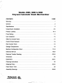
CONTENTS
Warranty
General
1
0 • • • • • • • • • • • • • • • • • • • • • • • • • • • • • • • • • • • • • • • • • • • • • • • • • • • • • • • • • • •
Specifications
2
2
Unpacking & Installation
Product Loading
3-5
6-13
Price Setting
14
Coin Collection
15
Slide Out Control Panel
15
Control Panel Removal . . . . . . . . . . . . . . . . . . . . . . . . . . . . . . . . . . . . . . . . . . . . . . . . . . 16
Rear Access Panel; . . . . . . . . . . . . . . . . . . . . . . . . . . . . . . . . . . . . . . . . . . . . . . . . . . . . . 16
Storage Compartment
'. . . . . . . . . . . . . . . . . . . . . . . . . . . . . . . . . . . . . . 16
Machine Configuration Chart
17-18
Electrical Service
19-22
Electrical Trouble Shooting
23-24
Schematic . . . . . . . . . . . . . . . . . . . . . . . . . . . . . . . . . . . . . . . . . . . . . . . . . . . . . . . . . . . .. 25
Dispensers
26-31
Cleaning Instructions
Shipping Policy
33-34
Parts Return Form
35
Assembly Drawings
36-58
l'olJ~8nd -e. fiJl:l...
CONWAY. ARKANSAS
32
l:iI}1©
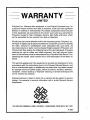
WARRANTY
LIMITED
Polyvend, Inc. Warrants this equipment, to the Original Purchaser only, for
a period of twelve months from date of shipment, to be free 'from signi'ficant
defects in material or workmanship. Purchased components which are part
of this equipment are warranted to the extent such parts are warranted to
Polyvend, except for filter cartridges, starters, light bulbs and 'fuses, which
will be warranted for two months 'from date of shipment.
Should any part prove defective within the warranted period, Polyvend, Inc.
will repa.ir or replace (at its option) the defective component, but will not provide
the labor, removal or reinstallation costs associated with such parts. All
returned products or parts must be shipped freight prepa.id to Polyvend, and
Polyvend will then prepay the shipping cost of the returned goods. Polyvend
reserves the right to refuse any collect shipment. Any part returned under
tern1S of this warranty must be accorTlpanied by a Polyvend Parts Return Form
identifying the model, serial number and a brief description of the defect or
failure.
This warranty applies only if the equipment is serviced and maintained in strict
accordance with the instructions given in the Polyvend Service Manual, and
that no unauthorized repair or disassembly has been done. Any defect caused
by improper source of power supply, abuse of product, accident, alteration,
vandalism, mineral build-up or improper cleaning or service techniques will
not be covered by warranty.
Polyvend service or repair to items not in warranty will be subject to service
charge. For warranty or service information call or write Polyvend Service
Department.
~IA>
~~
Dol,..,8ndllC
700 SOUTH GERMAN LANE, CONWAY, ARKANSAS 72032 (501) 327-1301
A-559
-1-
I
I
~
POLYVEND MODELS
Automatic Snack Merchandiser
Service Manual
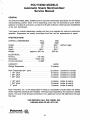
GENERAL
The Polyvend 4000, 5000, & 6000 machine has been developed speci'fica.lly for the display
merchandising market. Each of the dispensing units may be activated by push button
selection of a letter (A to E) and a number (0 to 9) after sufficient credit has been established
in the coin mechanism.
Two types of module dispensers (wedge and tray) are supplied for optimum production
selection. Dispensers are readily removable from the front for replacement or repair.
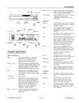
SPECIFICATIONS
OVERALL DIMENSIONS:
Height
Width
Depth
Weight
ELECTRICAL:
Primary
Secondary
Current (primary)
FULL
SIZE
72"
37"
28'12"
(approx.) 600 Ibs
MID
SIZE
66'12"
31'12"
28'12"
520 Ibs.
(without legs)
110 VAC
10/24 VAC
2 AMP
CAPACITY:
Wedge Dispensers
EACH
12 pieces
Helix Dispensers-3/4" pitch
1 1/8" pitch
1 3/8" pitch . . . . . . . . . . . . . . . . . . . . . . . . . . . . . .
1 5/8" pitch
22
16
12
10
1 1/8" pitch
1 5/8" pitch
2" pitch
pieces
pieces
pieces
pieces
14 pieces
10 pieces
8 pieces
(crackers
(crackers
(crackers
(crackers
& candy)
& candy)
& candy)
& candy)
(chips & pastry)
(chips & pastry)
(chips & pastry)
Note: Polyvend, Inc. is not responsible for faulty or overloaded circuits within the facility
where Polyvend machines are installed. The exact load imposed by the machine is stated
above. The sum of all devices connected in to a particular' circuit will deterrriine the total
line load.
FOR SERVICE CALL POLYVEND, INC.
1-800-643-8250 OR 501-327-1301
1'~IJ~~nd .... fiJR.
CONWAY. ARKANSAS
~©
-2-
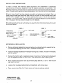
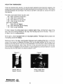
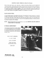
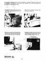
INSTALLA1"ION INSTRUCTIONS
In order to comply with electrical safety regulations and Underwriter's Laboratories
requirements, all electrical equipment must be properly polarized and grounded. The
Polyvend machine is wired so that it is properly polarized in accordance with the electrical
code. If the wall outlet is wired and grounded properly, then the vendor will connect properly.
Shown in view A and B are two properly grounded and polarized wall outlets. One is a
three wire grounded type wall outlet (see View A), and one is a two wire wall outlet (see
View B) with an adapter in place. To make a polarity check, use a 115 volt neon test lamp
as shown, or a volt ohm meter. The hot side of the circuit should always be counterclockwise
from the ground terminal, (which should be at the bottom).
Should the polarity at the wall outlet show any way other than that shown below, the outlet
should be rewired.
VIEW A
THREE WIRE
GROUNDING TYPE ___
WALL OUTLET
CIRCUIT GROUND ----+-~I :"'11--+- HOT
OR COMMON
VIEW B
TEST LAMP
" --- TEST LAMP
CIRCUIT GROUND
OR COMMON
---+--.
L . -_ _ ....
GROUND
HOT
""'-- lWO WIRE
WALL OUTLET
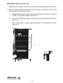
UNPACKING & INSTALLATION
•
Remove shipping material from around machine by cutting the shrink wrap at the top.
Cut downward keeping the knife over a cardboard corner post.
•
Inspect for damage resulting from improper handing and, if evident, file claim immediately
with the carrier.
•
Remove the machine with an appliance mover or hand truck. Tip the machine backward
onto the appliance mover or hand truck. Then remove the lower shipping skid.
•
Place machine into position and adjust leveling legs (See No.1) so it is level and all
legs touch the Hoar.
•
Locate small envelope inside delivery compartment and remove keys.
•
Open service doar (See No.2) and remove all internal packing material.
-3-
UNP,lCIIING & INST,lLL,lTlON ConI.
•
Remove til. ron changer f'om ,hot lOp of m.Chlne, l,t IIQI alroad1 inslall<>d in mach""'l
Remove env.k!\><! wnh~"", decals lr"'" product
on tIl"r ,a""",,"v. drspe<1S&' locations
o.
b.
""ii"",~
comp.nm_ Plac.
~. di""""_'lw~h pla.t", numbm 'abl- Place the
numbe' I" "'" OII1l1n. P'OVIO<>d (5. . No 3)
11.~. t'ay:
"''''~ o1f>c"llu,"
""".1,
ot>ove 1M
Place ,he priee decal on the 1'0111 of ".~, iUS! to ,he ,;gh' of tho f1lJmt>!Jf
($e<t No_ 4)
c.
,
,
Gum & MUl'
(SM NO.5)
""'ion (il usedl: l'1ac. ",ice "",,"I on t,,,,,, CQWjjng .s shown
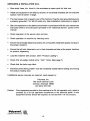
UNPACKING & INSTALLATION Cont.
•
Save extra fuses, etc. found in the envelopes as spare parts for later use.
•
Install coin equipment in the slide out drawer, (if not already installed). (24 volt only)-see
Caution note at bottom of page.
•
The main power cord is taped to rear of the machine. Plug the 3-pin grounded plug into
a properly grounded 115V 60 HZ outlet only. (See Installation instructions on page 2)
•
Set coin equipment to the desired price levels in accordance with the coin mechanism
instruction sheet or the instructions provided in the "Electrical Service" porlion of this
manual.
•
Check operation of the service door and lock.
•
Check operation of machine by inserting coins.
•
Ensure that all wedge dispensing chains are running free inside their guides and stop in
the proper locations.
•
Ensure that all helix dispensers run in their channels and stop at the proper locations
for product dispensing.
•
Load the machine with product. (See "Product Loading")
•
Check that all wedge module arms "click" home. (See page 7)
•
Check that the helix trays latch.
•
Electrical panel sliding drawer must be completely closed before closing and locking
the product loading door.
If additional service manuals are required, send request to:
Polyvend, Inc.
700 South German Lane
Conway, Arkansas 72032
AIC (501) 327-1301
Caution:
Coin equipment provided in this machine is for 24 volt operation only, which is
provided by a 24 volt step-down transformer in the electrical panel. If coin
equipment service should be required, do not test with 110 volt circuitry.
""IJ~end .... ~
CONWAY. ARKANSAS
~©
-5-
PRODUCT LOADING INSTRUCTIONS
1.
Chips/Pastry
2.
Candy
See Samples
"al~~~nd~
CONWAY. ARKANSAS
liP<.
(ijJJ©
PRODUCT LOADING INSTRUCTIONS
All prOllu<IIo""1n9"'
Ih~
4000,
~OOO,
0"0 oj ,no key. oroviOOd, "pM tlHo door '0
There .r~ !h'e" d,"e,~el
(1)
(2)
(3)
WM\JII-pr"'""I~
acc"",p',.~o Irom tno !r<>nt.
tt. ~roo"ct Ioadi"ll ccmpart""'"t
5 6000 Sen.. '.
U..n9
11'' ' ' o! d""eMO"
Icc D.ggM prOllu<1
HOI,.-I .. b.gQed or llO'e<l "0"..
Gum 8na M,n, Drspe<lS8'
II) WEDGE DISPENSER
To I""d, 'e'u.e1he 18K:h on each .mpenser
tho .I>:;le
h,~
~.
'hown ;" FIQUAE 1 lrod puD fotwJrd "n"l
tM $!Oj>.
",M"nOd .,to. W""9" .... mDlv . . .Mwn '" FIGU~E 2 Th" can b. dono
m"o~ W"~" hOwe_. iMf"lo. De" way whlcl> oor,,,... 01 in$M'rlQ!M bag ,oto tM we-Gge
., a~ "ogle ""d .hCIOn-g \he bag until """te,M rn Ih~ W""9". D<l no! .Il.mo! \Q ""'" lMt
po.,~"m M Mch cMin. R........e produ<1 by .. e.Slog le'er "p t>oo .. r>d D.g
Each
D'~
WARNING:
00 NOT ATT~MPT TO PUll PRODUCT FADM THE !lAG DtSP~NSER
AT ANY n\lE SUCH ACTIDN WILl- EtTHER JAM THE MECHANISM
OR PULL n-IE WEDGE ASSEMBUES APART
HEll~
(2)
I! _
DISPENSER
!", narrow
pr""""........
~
ta•.
FOR AOOITIONAl RAILS URDER
PIN 182<lUl1 !O<~. 20lXI ~.
PIN la244~ !o< """"'114000. 5000. 8. 8000 .... ,..
PRESS ON SP...cER RAil
INSTAll AS SHOWN
(R_'"~.'O
HELIX
TRAV
TAll PRODUCT SHOULD REST
ON TRAV NOT ON tfEU~
aol"" opaat>g)
'""
HEUX
HELIX TRAY DISPENSERS
.r.
T""'G
se"",al ""Ii. P'ICIln. TO ass<Jf. " ' _ o~'au,," an<l m"",m"", <:apa(:Ity. t""
_UCl ""'. 5I>OuId dCIlW1f1' malC~ "'" (lPfl<"OlI>g """'... n I.... _"'II 01''''' ""'''' TIIe_"'"
sholJOI Ii' beI""",n '1>& .. 'nd.... Of I"" ~""" GO .. NOT 10 l>G 'ilIf" 1>01 .1>0<'01 "" 1f>(I" '"
"'" OlW"lng_
T.... f'oeI.. ""es 1'''0<1 bGIow ma, "" ulIG¢
314" Hah.
, 11l1" HeIi.
rr~lnn ....
Candy ea'i
m", C.n<Iy eo"
Hati. ('-!I<lium ca"", Barl
, !ill" HellO (LO'911 Ca"", e.,)
Spli! Hel.. ,",vall."'"
2"
HIIII. (C~1ll a P.-.yj
, 5JIj" Heli. ("''''''urn C~II' or Pallr)')
, 1Ill" Heli. (L.'lII Coo......)
, 3/8"
.'op
h _ , ,.1&8& , .... "",,"a p1Q\Ic:
on _
ng~1 '" trill' u~,.,. ~on' e<>goo ol ,n•
....." Ira, wn'i<I pulling 10M"" on t.... 111Iy. p,. lhIt "ay out unt~ H "".","lI T~.n I., 'I
h~
IMO tM 1oa<l0lg poaition,
_n
"l thIS poo","
chfloc~
m.l NCh
~aIi> II",
ilJ 1ltOP'" PQaiIion. n.aligu" ",-, "''''''''' and
'm",Ol'fIrIy _hO.....<I 1la/j0ft.
ptOIIUCIll,u..eenlOlloCf\ -1n9 01 1M lleli • ."lM, IIIe
na"", 01 I"" prO<l»<:lla cbpIal"'<llrlll'lfwor<l, Boa "",a l<> """,al"'Qduc1 a~ II'" ..ay 10 In.
IlCIUom 01 I"" nav Of\d ldI
aiiOll DaC""""<lI, Filii""" lronllO bac~ and De Sule
nol 10> ml.. an, po..ionI. M'" IOlIng, II~ l'Onl ot I'ay ..... OU.... 11., ~""~ 1".8 1M ".y
unlil ttle talC~ I. engavecl Clle<k tIIat "'tell Is lull, engallOd by Pul~ng !o,.... <1 01\1,., and
SlartI"Il al !'OOl oj "'" l1ay, _
!,"" """
onsul1n!llhal I.... tl1lY ooas """ a<lYancG lMIl'Ofl" Ia1C~
Can<ly 11e1" ,n
o.lanl Pa.<I"'"
Cnlll!L"gei
~"
in 0aI&r\l POG"1on
"l)TICE
Special _"II NrlllCl_ rOJ bO. I'fll8 prCOUCl Of llIieI< Kal _
",,(!y.
Cencty T..., 0nIy11
C..... ~ _ ..., tloar.WII h.... I\aI OJ Mml4lll1 _ I wltieh ... thid< el'lll ""'t,
Po/JYMCl has designed Inle O<lt tMlil< lNI ,..l<ibIlily 10 tit 1(l()qo4,
el "" -ending ell"'.
lyPe cI JIfCIII>CI. O,......--.g r.... _hlcn cl tI>e".... -.:I rtlut l ltIck•• _ I""'''' I bill
alspenll"ll lot lll;lQd procIUCtI. 't"0<l limply unlcck me hell. by rwlallng I
".~.
cDI>/I!e,o_1II ena cotll''''''''lll.... tolelictl 90
nd ......,k 1M _
by IWII1inIl
Cloc:h'MM 10 Ie I~
Tilt _
IhcwlO Ot In 11>11 _I\IOtI . . """"" Dllcw
dtg,_.•
<Iegt_.
Figure •
,-90
ItQm
tICttnIlI let lNok OJ bell
1(1Cli..
~_
SPUl
HEll;l
can _ . thl ceupIjng tIaI
lWO loc:ldng piM ena I.... _"'"
.... yell
I1IIlt IIcI&. Unlcck by tMlti"ll 11ft
-.:I leek by
......
.,.
_'ing r1g1ll .
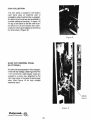
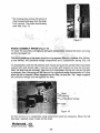
HELIX DISPENSERS
Visual observation of the helix trays and the assembly drawing will aid in the removal of
these assemblies. However, notice of the following instructions will 'further reduce handling.
HELIX REMOVAL
An individual helix can be removed for cleaning, repair, or replacement with a different
pitch while the tray is either in or out of the machine by grasping the helix and tWisting
1/4 turn counterclockwise. Then pull forward.
HELIX TRAY REMOVAL
Lift the white cam on the right side of the helix tray to clear latch and pull forward until
contacting the stop that allows the tray to tilt down for loading. Lift the front of the tray
and lift the same white cam while pUlling forward. To clear the machine, grasp the tray
at front and back, lift it out to place on a work surface.
To replace, reverse the operation. Grasp the tray, engage the rear rollers in the track and
slide the tray high to clear the stop and push into the loading position. Load product, lift,
and push into the latched position.
""I,~~nd..e fiJl:l..
CONWAY. ARKANSAS
li{Jf©
-11-
,
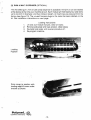
(3) GUM 1\ MINT DISPENSER (OPTIONALl
This ''''~ '018<1 gum. mini Of lUDe C&r1d~ dJSjlonser I. avalable I~ ~~ !o,m 0< can be Install&d
at 1M laClory allha tlma yOur macNna I. ~ui~ Eacn modu~ will tdd !W~~lY'k>u, (24) [Illm.
up I<> one Inch in di_~ •. and ~"" il>Cnu in !engtn. All ",ac!1In$! a'a praw"ed I""" <lie
lactot~ ,see ligu,a 10). TM unusad harnass plug. 10 lna mol'" Ii,ma... inatall~ on ,na
k,!. see mll.n.,ion InSlruClions on~" o.ge
LOMinO '~structlO<1S
1. Lm .nd oull mMu!e lorwa'd. cle., oll'ac~,.
2, R.mov. sid. p1.tO ar1d 10M JIfOd""I. (5" b.~)
3 FllHnSl'~ sid. p1.le .r1d <...ISa ~uro
~
Fl.'o'og ..'" ",.chine
'1.
Loading
Po,Ition
5n.p CO\l$f in oo,;toon wi!n
".dj~g edge of COVllt unde'
blackel as shown.
-12·
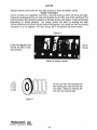
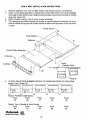
GUM & MINT INSTALLATION INSTRUCTIONS
1.
2.
3.
4.
Remove deflector from front of false bottom and discard screws and deflector.
Attach retrofit plate assembly by sliding plate under false bottom so that lip engages
front edge of false botton, (use 2 large screws provided), and connect harness to mating
plug near power box.
Attach hinged cowling. (Use 2 small screws provided.)
Tilt cowling up and slide modules into tracks on retro'fit plate as illustrated. Lift up on
front of module during last few inches of travel to allow front stop block to fall into notch
in track.
False Bottom
Deflector
Retrofit Plate Assembly
#6 screw~
I
Cowling
r
Tracks
Retrofit Plate
Module
5.
ATTACH SELECTION NUMBER DECALS TO COWLING FRONT AS FOLLOWS:
Model: Tom's Super 35
I
Model: PV4000 & 5000 Series
Press
Press
A5
A6
Press
A7
Press
A8
Press
A9
Model: Tom's Spindle & Helix Combo
Push
Push
Push
A6
A7
A8
Push
B6
Push
B7
l'''IJ~endlllC fiJR.
CONWAY. ARKANSAS ~©
-13-
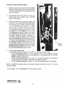
PIIICE SETTING INSTIIUCTIONS
O\>e<ll!>e MtV!C9l1OO< ana ""~ ",,111>&_"9
<:onl'_
10 obi.... aoxoa 10 .....
bo/IId
l~e ""' conl'_ bOard dlrlO:ll'/ _ t h e
~_
«>in l'II6CIIaJUIII.
~.
Pu5n MOOE swnch (Il>Il ,witcn
M
1M
C(l(I-
,,<>11M bOard. and _ . . (SN 00''''011''
plc'ure la the right.)
3
I,ll~e 8Ity
e """"_
"""'ioI'>
by pr....ng
a 1*'.ter ....,
n.e CI'''''''' prl<:e..-il be d<5P!eyed
int,_ Il'lceln
nlc~I' Incr...."'"'": Il''''
Ta -=rene ~; Il'_ '"•.• _
rSI.n<l price 18
rllel" lile l>ut!O<'I.
Wmo<e . .lKUonI ... 10 be "'"' It ""' ..,.,.
ptbpr... '"S". (TIle beepef .... l Wfn "" ana
"" repNlIll/y dunng ~ ~ ) No..- _
8""'" Mltclkwl 10 be set II 'his pn"•. IA.-II
TO
"g"
,...,/Ied.
lfllt " _ _ '........ "'" "'""",__ ',J
P'""""lI "0"'
w,1I . ."'" 'P' 10 "'" --.... """'. lI"""a'
"1IP3 undI .. Nlltcllon pr~ ",•• wen ...
Tl>or venae:.- _ b e _ l O 1M 5aIH Moalt
by Pf1II1i/>g Il'Ilt M<xl\Ir S'wiIch "'larn Of " will
IUIemIIJcaIIy . . . .n 10 Ihlt ..101 _
25
.."."od•• ft.. "'" operltllon hu l>Hn "'.ade
00 NOT IofgM lO label lhe ..... 01 I'" COY..
bar wilh "'" ~ IlfIClt ""':ket.
•. To _ _ ... _ _:
__
Switch lO pW:e Ihlt CooI,oIler in lhe Sefw::lt MOCle. 11>8,,,
To ....... - - . . .
"g'" Each _ _ .... ~ run In I"'" _ng "Ill III•
..lltcllon ~.,., ltIe Pfl<e 01,..., _,.,., In l\lfTlllartmg ... ~h "E" end "'"
P,... _
~......-
...
1"."
.
To run 1 1'lDfUon1ll rowlog .......), pr.... '"7". ,""" pr... row IIn..- Eo<::n-uon
In thII row wiI ,..., In lurn 5''''''"9 wilh t/I8 hig_ numWl'_
To"", IncIMliuIoI _0:0-.. 1"'" "9" 1Iten l!>o -.;on ...... end.....,t.<
NOTE: To STOP. I"""liotl...,., I I
09I".11on IlOpI
_'"II III ..Iee"""" press And IIOId "0" Uflhl ,lilt
COIN COLLECTION
r ... coin ~nk It IOCM.., 1ft In. boltam
flVIIl ""na _
aI ~ er<l
.. '...
AI>
<.
_,nelronl_.~,
ap_ IocIo .na key ar• •••1laOIo to
proyt<le
.Odi'__ ""'Y. To _."ft
'.... '00 aI "'" l>enk 10 I,," 10" u... ~.."
l > e ' _ . UlIer<l_coin l)enk,
en'oIlIY "'" col........ '"'PIOOO Dy ''''''''11
'...
proc_. IF_" 81
SUOE OIJT CONnIOt. PANEL
(ElECTRICAL)
GU,_
in,.. 0DIfIIIIfI"""', .... _
(SIt FJot.d 9f 11>00
11~.I,.n"",""". IIgh' !>ell••. "'"'" If.
1<lc:1I'" ., • ~., tw)• • rIIe".., 10 III.
''!lhl
in I,," bod< 01"'" S/Qfove
A.l ~
rN''''_
"'••. (5&& Fog",,, 10 lot' nogh YOiteg<l
.lIClrlo:el bO••)
.,.
CONTROL PANEL REMOVAL (Slide 0tJ. Of....'l
"''''Oce ooor OpM. P!'II • sl"'" our orawe' 10 1/141",01> R.1Wl up f,om _ I".
60""""'", 1M 'N' of,,,, G'.w..... d ""scOlVlOCl 1M I""" M,n..s <_,""'"
Naw 'e'••'" "'" SlOP Sll' .... I.n,,,, lOp 01 P,._~.ng P'JIl dr.WOflO full open Rlmove
W,ln
o,.pI"~
(4!1Ct.... from _
'" <:«lIe< o! <Ir... e< Two mu" tie '~llIro<lgt1lhe1"'\1" ""'"
'" <:«llo< _1OCIion Be c:arellll HOT 10 _
dra..... to fall _ _ ""'.. tel.....
men 1"'."., ....._ ~om 01'_. ReverM In.. procedure to ,..n$lllJl,
REAR ACCESS PANEL
A 1"'11" 10:<... "",*111"_ '"' 1/141.- of \I.. macIllr>ll n. <>nIy ""'POW ,. Ie poIIrmi'
ac<... 10 Ille """"ll in ,Ile rear of !lie "'.,,,,.... To ,I""" oL
fM hI'. proviOed
.., 1110
pans I>ag. InH<1 I/I4Im inlO tt>e 10<.. InIl
"'eo., P.,II lOll IW3V from
sP&'.
""10<:,,
oj "'" <lOC>" .....,. '<om "" .-... ....:l ............ H.nc". c.o,,"u~y
c.o.,..,.,1 ft>on ... the _
'0 1"""'"
NOTE:
~
Rear
loci,.
_
0Im.ge.
.c::c::a."".... it"" co',,''''',,''''. 01111' ALL SERVICE CAN liE HANDLED
FROM FRONT OF
~CHlNE.
STOfIAOt: COMPARTMENT
TM ........ a>nlportnW'llll_ - . . .
mo prod"", <looplay " ....... I.IO:~ d
tI'/ """"""ll1M fr<:ll'llllClOr. l.M.. room lot
1'>01 delrvwy a>nlporlmerll _
UI"'lI tM
0\0<0\10> Ire.
GUM & MIN'! I-tARNESS
'lOVOlI FUSE
lAMP STAATER
HIGH VOLTAGE
£LEC"UCAL BOX
COIN BOX
.,.
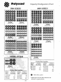
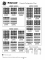
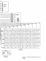
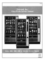
Capacity/Configuration Chart
6000 SlmlES
MODEL PV2210
• .
""'.., . ,,-
Snack
~
~.
>-.
Product Siu ctpabi&!w
tkn.
Thi<:k"...
II Coon,
,,-,
6 Coun'
.
l~"
~.
PtOOlXl
JYIi.
Thickneso
14 Coun!
I"
10 Coun'
lW
8CDUn'
I~-
'",""
Candy
tkh.
ProdIX'
Thick....,..
22 COY,,!
14 Coun!
12Coun!
,,r
1\1-
to Counl
IIl-
Thicknn.ll
S·
,,,-
17 Cou,,'
12 Coun'
10 Count
.
.Opt
120
""" oM ....... _
to
5 .....,""'" ...0
,,,,,,,,.;0. .......
Capacity/Configuration Chart
6000M SERIES
•.. -.
N_
~
. .•
~.'.
_
.
'
SOOOM SERIES
•• I..
ee.
•
I'VS&.U..
P\I~
CAPIoO" ....
C»IoaN..
_
..... _101
CAP"""" 'w
s.-~
IVliK
Thick,.,...
14 Cow",
I"
10 u..,n'
Ill"
Cwn.
I~'
•. _-. . __._.. . .-..<...-t
-
~_
I'focb, s... c~'Y
ProcIucI Candy
Produc,
I1tb Thickncu
Z2 Count
"'14 Count
I12 Count
Ill"
10 Couro
Ill"
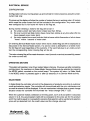
ELECTRICAL SERVICE
CONFIGURATION
Configuration will occur during power-up and will test for motor presence using the undercurrent test only.
On power-up the display will show the number of motors that are in working order. All motors
which meet the under-current limit will be included in the configuration. Any motor which
was configured but is not found will have its fail flag set.
During normal vending a motor's fail 'flag will be set If:
a) the under-current test fails (motor draws less than 35ma).
b) the over current test fails (motor draws more than 444ma at any time after 250 ms
have elasped since motor start).
c) the motor meets the current limits but fails to home within 8 seconds or fails to leave
"home" within 1 second of motor start.
On entering Service Mode those motors which have a fa.iled flag set will be displayed as
discussed in the Service Mode section. If a service vend is attempted on a failed motor
the fail flag will reset regardless of the outcome. If the vend fails due to an under-current
test the corresponding motor missing flag will be set.
The motor missing flag will be reset whenever a vend (normal or service) successfully passed
the under-current test.
OPERATING MOTORS
The system will operate in one of two modes: Sales or Service. On power-up (after completing
configuration); the machine is in Sales Mode. Service Mode may be selected by pressing
the MODE swtich mounted on the control board. The system will return to Sales Mode
if the MODE switch is pressed again or after 25 seconds of no Service Mode activity.
SALES MODE
In Sales Mode the controller will control the dispensing of products according to customer
credit and selection inputs. The controller will cOITlmunicate with the coin mechanism and
as credit is entered it will be displayed. If the coin mechanism indicates that an exact change
situation exists the controller will illuminate the "exact change ONLV" LED.
When the customer makes a selection on the key panel, row A to E and (within 5 seconds)
column 0 to 9, the accumulated credit will be compared to the price set for this product
and if the credit is equal to or exceeds the set price that selection will be vended and selection
price will. b~ deducted 'from the credit value and the change returned.
I''IIJcend..e Jill<.
CONWAY. ARKANSAS
~©
-19-
The vend will be considered unsuccessful if the motor exhibits under or over current operation or fails to home within 8 seconds. The vend will not be attempted if the motor has
already been detected as fa.iled or if the selection made is invalid (not configured). In any
such case, credit will not be deducted and the "Alternate Selection" message will be flashed
at a 1 Hz rate for 10 seconds or until a new selection is made.
If there is insufficient credit for the selection made the "Selection Price" message will be
flashed at a 1 Hz rate for 10 seconds or until enough credit is added and the product
reselected, or a lower price selection entered. Correct selection price will be displayed during
this time. The original selection will have been cancelled.
If power fails during a vend, the selected motor will not be reenergized when power returns
and its fail flag will be set. All credit will have been lost.
SERVICE/PROGRAM MODE
This mode will be entered by depressing the "MODE BUTTON", located on the controller.
The numeric keys of the alphanumeric keypanel will then allow the operator to program
and interrogate the controller.
On depressing the MODE switch the display will sequence through (for 1.5 seconds each);
the alphanumeric selection codes of any motors which the controller believes to have failed.
Pressing and holding "0" button will abort this sequence display. If the controller has not
received a credit command from the coin mechanism within the previous 24 hours of
continuous powered operation, "CHANGE" is displayed.
A selection menu of program modes will now be available to the operator. Control of these
program modes is by use of the numeric keys whose 'functions are listed below:
Key
Key
Key
Key
Key
Key
Key
Key
Key
Key
0:
1:
2:
3:
4:
5:
6:
7:
8:
9:
Cancel Multi-Set Price mode.
Cancel Multi-Set Price mode.
Display Configuration.
Remove missing motor from configuration.
Decrease Price.
Enter Multi-Set Price mode.
Service Vend by individual selection.
Service Vend by machine row.
Service Vend whole machine configuration.
Increase Price.
The operator will now be capable of displaying the price of any product by entering its
alphanumeric selection code. The operator will be allowed 5 seconds to complete entering
a selection code-else it will be cancelled.
To exit from the SERVICE/PROGRAM mode the operator may press the MODE switch
a secon-o time or allow a period of inactivity in excess of 25 seconds to elapse. Either way
the machine will revert to the SALES mode of operation.
""I,~~nd..e. JiJ:J<.
li(J1©
CONWAY. ARKANSAS
-20-
The following paragraphs explain each KEY function listed above in more detail.
KEY 0
This key will be used to cancel from the Multi-Set Price mode. This key will also be used
to terminate the execution of the Service Vend by machine row or Service Vend by whole
machine configuration modes.
KEY 1
This key will allow you to cancel Multi-Set Price mode.
KEY 2
This key will be used to check motors (configuration test). Then displays the number found
for 1.5 seconds.
KEY 3
Press and hold button until several "beeps" are heard. This will remove any motor(s) that
were previously configured but have since been removed and are no longer wanted in the
existing machine configuration.
KEY 4
This key will be used to decrease the price of a product. If on entering the program mode
the operator wishes to alter the price of a product he will first select the product by n1eans
of its alphanumeric selection code. The current price of that product will then be displayed.
To decrease the price (in base coin units) he must press KEY 4. If pressed for more than
0.5 seconds, the price will be decreased at a 0.25 second rate until the key is released.
If the minimum price is reached (250 x base coin unit), the price will roll over to 0 and continue
to be decreased. Releasing this key will return the operator to the selection menu of program
modes condition. (Warning: If price has a letter to the left (Le. C.45), the letter represents
a high price, (in this' case $12.45). A = $1 0.00 B = $11.00 C = $12.00.)
KEY 5
This key will be used to set the same price for many selections. The desired price is 'first
set by using Keys 4 and 9 (see appropriate sections) for a particular product. To set this
price for many products Key 5 will then be depressed (beeping notes this mode) followed
by the alphanumeric selection codes for the desired products. On completion of this
operation, pressing Key 0 will return the operator to the selection menu of program modes
condition. Inactivity for over 25 seconds will return to the SALES mode.
KEY 6
This key will be used to service vend a particular selection. Depressing Key 6 followed
by the alphanumeric selection code will result in the controller attempting to vend that
product. During the vend cycle the display will indicate the selection price. If the vend is
unsuccessful or the motor is not included in the configuration the horn will beep 3 times
and the display will show the failed selection code for 1.5 seconds, otherwise it will blank.
The operation will be returned to the selection menu of program modes condition.
I'Qls~end-. JiJR.
CONWAY. ARKANSAS
li(!f©
-21-
KEY 7
This key will be used to service vend a row of products in the machine. Depressing Key
7 followed by the alpha selection code identifying the row will result in the controller
attempting to vend each configured product in the row selected. During the vend cycle
for each product, the display will indicate the price of that vend. If any vends are
unsuccessful, on completion of the row or prior use of the 0 KEY the horn will beep 3times
and the display will sequence once through the failed selections, displaying each for 1.5
seconds. If no failures, the display will blank. The operation will be returned to the selection
menu of program modes condition.
KEY 8
This key will be used to service vend every selection in the machine. Depressing Key 8
will result in the controller attempting to vend each configured product in the machine.
During the vend cycle for each product, the display will indicate the price of that vend.
If any vends are unsuccessful, on completion of all row's; prior use of the 0 Key, the horn
will beep 3 times and the display will sequence through the failed selections, displaying
each for 1.5 seconds. If no failures, the displays will blank.
KEY 9
This key will be used to increase the price of a product. If on entering the program mode
the operator wishes to alter the price of a product he will first select the product by means
of its alphanumeric selection code. The current price of that product will then be displayed.
To increase the price (in base coin units), he will press Key 9, if held depressed for more
than 0.5 seconds, the price will be increased at a 0.25 second rate until the key is released.
The price will roll over 'from 0 to maximum price (250 x base coin value) and continue to
be increased. Once released control will return the operation to the selection menu of
program modes condition. A price of 0 will not be considered as a valid price.
l'oIJ~~nd~ ~
CONWAV.ARKANSAS ~©
-22-
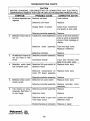
TROUBLESHOOTING CHARTS
CAUTION
BEFORE CHANGING, DISCONNECTING OR CONNECTING ANY ELECTRICAL
COMPONENTS, REMOVE THE FUSE OR UNPLUG THE MACHINE FROM THE WALL
1.
2.
3.
4.
5.
SYMPTOM
All coins deposited are
rejected
PROBABLE CAUSE
Machine not level
CORRECTIVE ACTION
Level cabinet
Defective coin mech
Replace
Display blank, no power
Check fuse, transformer,
and power at wall outlet
Defective controller assembly
Insufficient credit established
Replace
Check to see that selection
price is same as deposited
amount. Note message on
display.
Defective motor assembly
Test vend bad motor.
Replace if defective.
All selection motors do
not run (Test or free
vend)
Defective controller
Detective controller asserTibly
Replace
Replace
Connection broken
Selection motor does
not complete cycle
Defective 'full cycle switch or
defective motor
Trace wire harness-See
Note (1) for color code
Replace motor ass'y
Selection motor fails to
turn on
Selection motor continuously cycles
Defective components on
motor PC board assembly
Replace motor ass'y
Defective controller assembly
Defective full cycle switch
Replace
Replace motor ass'y
Defective controller assembly
6.
Two motors run simultaneously. See Note (1)
on next page.
Replace controller motor
assembly
Defective controller assembly Replace
Defective motor
Replace
Defective motor in gum and
mint motor circuit
Locate and replace
defective motor
Shorted harness or connector
Replace or repair
""I,~~nd..c. JiJR.
CONWAY. ARKANSAS ~©
-23-
7.
Incorrect change
dispensed
Defective coin mechanism
Replace
Defective controller
Replace
NOTE (1): The motors in the machine are arranged in a 5 x 10 matrix. This means that
all motors have a wire common to all other motors in that row. Exan1ple: all motors in the
"A" row have the white wire with black stripe in common. Likewise, all the motors in a
coluITIn have a wire in common. Example: all motors in column 2 have a red wire in common.
The following is the wire color guide for the motor matrix:
Row
Row
Row
Row
Row
"A"
"B"
"c"
"0"
"E"
Wire Color
White/Black
White/Brown
White/Red
White/Orange
White/Yellow
(Tray harnesses use only the White/Black since they can be used in any row.)
Column
Column
Column
Column
Column
Column
Column
Column
Column
Column
"0"
"1"
"2"
"3"
"4"
"5"
"6"
"7"
"8"
"9"
SYMPTOM
Selection no. shown when
service mode entered
controller.
"Change" message when
service mode entered
Black
Brown
Red
Orange
Yellow
Green
Blue
Violet
Gray
White
PROBABLE CAUSE
Motor Disconnected
CORRECTIVE ACTION
Reconnect motor
Defective motor
Replace motor
Motor jammed
No customers last 24 hours
Free jarrlmed motor
No action required
No coin mechanisms
communications
Replace coin mech.
Replace controller
l'''I~~~ndllC JiJR.
tiIlf©
CONWAY. ARKANSAS
-24-
,
..
.•- .
,
......
00'• ..,.,.,
I
,
k.
-"
••
,. .. c
~,
rM.•
•
.... .
•
•
..
..
..U.
..
..
_.•:•.J .. •
-<Ii
•• •• ..
•' c -
:e.,C-
••
0
0
.'--
"(~"N[ . . -
•
~
0'""0.'\
~-
I "U
, ~
,
•
,
0
0
,
0
_.
•
C_flh
" •· ••
... ' 100 ••
,
••
"
0
0
0
..
,
,
•
""
....• ... 0
,
,. "C
00" _ . ,
--
..
...
;:::
5O"" COO'
-
IE...."
I[
..
•
-
ClOOC"
,_nIH
~
., ,
..
...
, 0
,
,
,,
,
..
do
..u.
.. e ,0'0
f'"
.0' 0
co.•co
,
.1
~. ..
,
,.•
.
,111;1
·'
J'~
,
.. ,,
,I
..,•f---'
,
•
"
·
....O.
....
•
0 0
UOI<.
0
•,
••
•
,• , .
••
0
• •
•,
~
=ljj
,,
,.
••
,
,•
,
,,"
,
,"
Jilt
... 1
~
"
~·'oO··L
1'&
HL'
..
.. •, ...
, ,.. _l.{a
., 'Dc
, ••,I •
•
,
,.
0
0
-- -- ,, ."
j
, ..'..
,
-- ---.. ,"
,
~
,
..
rt=
.. , ..,
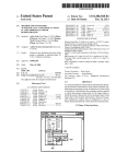
CABLE
406593
LC.D·
DISPLAY
" CABLE
....-~
I
t
~ ~
2 2
~ 10J
J
~ 10-
CODED
KEYPAD
4 4
I....- >--
~~
6 6
PP
...-r--r--
I-- "7
~
~
~ S. ~
~~~
~~~
.,. PP
F8
>--
9 9
~J.~
I-- 10-
~~
.1L.!L.!
J.!J!
Wt.n
RY
,'-
-
. . . . _----------------------J
1
MO:x,~S
(SE E DETAIL -A-)
DETAIL "A."
(so
PL"C0
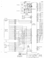
DOMESTIC (COINCO CONTROLLER)SCHEMATIC
E.D.C.
3-4-88
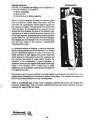
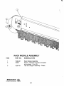
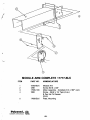
WEDGE MODULE
FIGURe 12 Ulullrat.. thlI wedoI ct>aln d",pense, Uslid In lhe machl.... ~ lXIfI8Illa of:
I} Motor Assemlily
"'m
2} Mo<lu~
3) Rae!< Module & Sli6e
DISPENSERS
"-tlblr
When a PfoduC! selection Ie m_, an eJeC1ric sllJfl'll
lrom the selectO' swil<:h .-mns !he molOI', IlIId lhe
conIl'<lller will supply ~ untillhe lWiloo apls thel
the vend "comple1e. Till' lldv_ lhe dlspenllng
chain """ ales>. At> the leading Chain segment moves
around lhe fI'ont oproc:1<al, the hook 01 the klllowlng legm..u.ell .. e ~IO acIlvele!he ....Ue 11"008 end lifter
01 the lfon1 ""l1fII'I"4, IorcIng \helllring lo8d9d cyIndoo
upwsnllSEl: FIG. 12). ~upwWd movement.the wedged gnp malnlalned on lI1e mercha1ld~ Ng,
and lhe beg d~ to \he delivery compartment,
complellng !he vend.
In a Pfevlous Mellon on loading, • "'amino .... given
abouI pulling ~oducta cut of Ihe dispenMf. It a fcfceluI
pullin. cIoIonwefd direction Ie used, Uwill cause the
rnetaI cyIindef's to _
against the ~a5lic dl_n_
chain eeg",enl. The prodUCI carlJlOl N reIBaaed erod
!he module may hllllll In cycle ....ic!I cauM!I lhe
macNn& to be it'Iopef81lw. It good Incllcetion 01
lIOII*"le pulling on \he blOB Ie chain PIIn5 round lying
looM In the machine. e_ H ..... too:e Ie used,
lI;IlwenQeII will be changed, causing IMlJUuaI failure ot
lhe dlBpenq cheln.
Figure 12
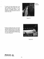
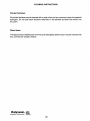
The comICIwey to "
prodUCl illCtUlllly euler. IlIId COf\5i5t5 III pusl'lln!l up on the
",hIte-<;llllored rele
Imrnedlately be/llnd the product Thil causes I... pro<luC! to
fall into your hand wiltooul henning r... ~ .
Tt.-e Ie a
PfIIticuIer I)'Pe of b"9 m_ 01 glualne
meteria! !hal cannot lie ven<l9d ";th
~ ~ dlaln, this Ie e coeled malerial !hal ~ the metal cyIln(lers ";th w....
causing lhe bege to fall out freely.
.r.
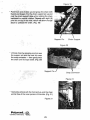
Dceasionlllly. dispensing chains mUSll>ll '''?laced '" '...,oired. These chains
tllned
on inllallation and Musl b<.o r.ffIQVfld w~h co,•. F'llur". 1:J.16 show lhe sequerICe 01
operations to aocompllah this laS~,
• Ra4ellSa the lalch on lhe dlspan$tlf and
pUll slkle number and Plica oul to its
Slop.
(F~.
• Aamove lhe dl""""",,' numtle,
price ctlYe', (F~_ 14)
an<!
13)
• Remove thO lICraw lrom \he aida 01 11>1
d~r {FIg.
Ill} which """'... as1l'Ml
SfO\> a"" pull oIkla lrom tho macNne.
. ':.-.'
>.
• Aal.... thO delotnl "","'II by pusl1ing
"'" I~ """ down and ~ing ~ 0Ul lrom
under the da1en1 apKer. (F~. 16)
• StilillOklinllllk\e verticl'l. lill bO!1Qm 01
chain outward and awa~ !fom Itla slide.
P~sn ~pward. Tna enain SI>oukl ea,Hy
,I>do 1"",.jF11I, 17)
Fillure 17
WEDGE ASSEMBLY REPAIR (F9J'. t8)
To ropaif tho 8S&Ombly and .-.pI""" damaged com_nlS. _ a tho ena;n and snap
QUlIn. damaged link.
This link i. made "'P 04 Ille bosIc c/IPl hou.l"ll MlImant (1IIAck). a cylInOo< Uho' (WMe).
a slide (WMot, IWO cyllncIrtcIIl wadQe component' and a comp<asslor1 'p<ing, (Fig. t81
To dl"""",b~. hold the link between boln 1laIId' and pustl Ino cylinder IIMor Slub .nahs
Ou!WI'O wllh boln tnvmt> nells. II w,1I pop QUt (relain with fin,...-.) 1M may tl(I rem<>ve(\.
No"'. tna slide "",y be '1IITIOVa<l. Taka u,a the comp,osslon spring 'SiI't losl a, lhe 'Mo
II 'amoved. Now. 1l'oI ~ will la11 , , . and lhO cyllfldrical wqs oompononlS will Iollow
when ltIe link ill inverted. WhIon •......,ml>Ilng tho 11110', l>8
IN "flal" edge is ~inS1
tho eyllnd'ic.1 w8dgo and not egeinat tho slide,
au,.
'""
""'"
Cylindriclll Wedge
Figure' 8
... lllnal ,omains Is to reassembta using Alplacement part, ., """a,sary. Whan tho Ifnk
nal been ,epal'ed. Silap II beck on the chain.
Figure 19
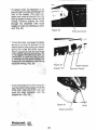
-
• Point front end of slide up and grasp the chain with
thumb and fingers. Pull the chain suppon pin up and
over the chain suppon slide while rotating the chain
backward to normal rotation. Repeat until eight (8)
pins are on top of the slide, which will allow enough
slack to unhook the chain. (Fig. 19)
Suppon Pin
Chain Support
Figure 20
• Unhook chain by grasping one link near
the suppon pin and the next link near
the snap connector - then gently twist
the chain until it snaps loose. (Fig. 20)
Suppon Pin
Snap Connector
Figure 21
• Hold slide venical with the front end up, and the chain
will fall free of the inner ponion of the slide. (Fig. 21)
Figure 21
I'QIY\'i4i:nd_ fi.J!J..
CONWAY. ARKANSAS
~
-29-
• To .....
-
cNin..,.
_"
....._or__
oro...
. . . . . IMM ... cheIn..., -V-It>e
..... o'
_ _ rn-_~
t.~_....
~ ~ po
- ....
1IIrOulIh
1M
hi
~
''''11 1Iw .....
.......
_
",
• 10_"'~. I'HIIllI9 "'" 011-.1
""''''1l by l...nlrog 1'" ~ to u.
Gel.... pOli1l0" uol """'1119
~..,t
"",ing ...., ....... It'III clet
t _.
Allon OI<JllPOfl PIll wM Il>I bIoCk.cllje
or IhIt nlCIClI.loI. (During thlllNllttIl. bot
NOT 10 _
IIw chain Iolwwd
or
u lI'M wouIcl mlMIlgn ...
MllIlIO'I plII-' u."",., _liming
-..kl be wnlng.) (fig. 2Sl
CIIr~
btCICw.m
~
__
__. _...
ol"'dWn_~'
_ ..._CII"-"."""'''
...,. ...
.... oaIi:lr ....... III ......, ....
- - ' pin. (FIg. 2-t)
1I~I)"Cfilnd_
-~
\.
_
..,.. III tIlIIIIIl
·
:~~~
-
.. ".",,,
'
--""'-=-:. .,.
Detent
Sprocket
• To place Ihe chain guide pins in Ihe
chain support slide. grasp the chain
with one hand and rolale it in Ihe
direction of normal rotation. while
holding the detent sprocket in with one
thumb. (Fig. 25)
Figure 25
• Continue pulling the chain until three
complete revolutions have been made.
With the detent spring in the detent
position. the leading chain segment will
be in the position shown il the timing
is correct. (Fig. 26)
Figure 26
I'QI 11:end_ ~
CONWAY, ARKANSAS
~
-31'
CLEANING INSrRUCTIONS
Painted Surfaces:
All painted surfaces can be cleaned with a clean cloth and any common brand of household
detergent. Do not use harsh abrasive materials on the painted surfaces that would mar
the paint.
Glass Items:
The glass product loading door and the push plexiglass delivery door may be cleaned with
any commercial window cleaner.
Pal)rc~nd~ fiJ!:l...
CONWAY. ARKANSAS
~©
-32-
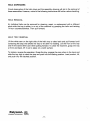
POLYVEND SHIPPING POLICY
'-
The following inforn1ation is being given to you to assist you in the safe delivery of your
merchandise and in expeding of freight damage claims.
Our terms of sale are F.O.B. our factory; the responsibility for damage in transit is the
carrier's whether it be visible or concealed damage. We have taken every precaution to
insure safe arrival of this equipment, but our responsibility ceases when the shipment is
turned over to the carrier.
The acceptance of this shipment by the carrier is an acknowledgement that the equipment
was delivered to them in good condition and properly packed. The carrier who delivers
this merchandise to your door is responsible for its safe delivery.
PROCEDURE FOR VISIBLE DAMAGE
1.
IT IS VERY IMPORTANT TO INSPECT ALL FREIGHT DELIVERIES, WHETHER
MACHINES OR PARTS, IMMEDIATELY. If there is any visible damage you have the
right to refuse the merchandise or to accept the damaged shipment. If you accept it,
make certain that you have the deliveryman note on the freight bill the nature and extent
of damage.
2.
After you determine extent and cost of damage, notify the delivering carrier's office by
phone, and confirm with a written notice within 15 days requesting an inspection of the
damaged merchandise. Keep a copy of the inspection request for claim purposes. Do not
destroy the packing material until shipment is inspected and claim is settled.
3.
When inspector arrives, ask for claim form. In filing a claim, you may make a cash
settlement with 'the carrier for the full invoice price of the merchandise or contact
Polyvend, Inc., telephone (501) 327-1301, and make arrangements to have merchandise
returned for repair, and file claim for repair charges. Do not return merchandise without
authorization from Polyvend, Inc., Traffic Manager. Ask carrier to return "DEADHEAD".
Do not claim more than cash price of machine plus freight.
l'''IJcend~ ~
CONWAY. ARKANSAS ~©
-33-
POLYVEND SHIPPING POLICY -
Cant.
PROCEDURE FOR CONCEALED DAMAGE
1.
If there is no visible damage, YOU MUST OPEN THE SHIPMENT WITHIN 15 DAYS
AND INSPECT FOR CONCEALED DAMAGE. If there is concealed damage, notify the
delivering carrier by phone immediately asking for an inspection, confirm in writing and
keep a copy of the request for claim purposes. If you fail to notify the carrier within
15 days of delivery, by telephone and in writing, the freight company is no longer liable
for the damage and will probably refuse your claim. Do not destroy packing material
until shipment is inspected and claim is settled.
2.
After inspection by carrier, file claim for damages at once. (See Item 4). On concealed
damage, unless it can be proven that the carrier is responsible for the damage, they
will probably want to settle on a compromise basis. Therefore, the faster you inspect
your delivery and notify the carrier, the better the chances are for full settlement. If the
claim is disallowed, check on the possibility of a compromise.
PROCEDURES FOR SHORTAGES
1.
If the shipment delivered to you is not in accordance with the quantity of cartons as
shown on your receipt, do not accept it until such shortages are noted on the Freight Bill
or Bill of Lading and signed by the truck driver. Failure to do this releases the carrier
from any responsibility.
2.
If the item that is short is not delivered within a reasonable time, then file a claim with
the delivering carrier for the invoice or cash price of the item that was not
delivered.
Claims for loss or damage will not be deducted from your invoice while awaiting adjustment
of such claims.
For 'further information or any other problems regarding deliveries of Polyvend merchandise,
contact our Traffic Manager, Gene Huss, at (501) 327-1301.
l'''IJc~nd..e
CONWAY. ARKANSAS
fiJR.
li(J1©
-34-
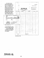
Of course, we at
Polyvend stand behind
all of our equipment, and
there is a 12-month warranty on all major components. All we ask is that
you label the part with a
Polyvend Return Goods
Tag and return it to us,
freight prepaid, along with
a Polyvend Parts Return
Form that gives us the
model, serial number and
,
FOR REPAIR OR REPLACEMENT
«SOH 127·1)01
L
Plrt ",
Oeoe
O.I.e«,
~,i.1
R~ml'"
No
1.".
1--
CO"'~( T(
Df' AC~ & ..... It..
THIS CAItO '0 .OOIOUS
",'N'EO ON "fO£IISE S'OE
02970
..,...
......
C-fO"
o
o
OV~
r------1--------
-_ .. _ - - - -
1------_·_-
,... NO
_ ~
1----·---
.... _
_.
Return Goods Tag
a brief description of why
the part is being returned.
We'll promptly repair
or replace the component
and then ship it back to
you prepaid.
3=--==---+---~--- ~---..
-1-----------------f--
-
-.-_·t.. -_-·_·_· -. -------tOG IS
-
.
__ ._--
1"".'
Parts Return Form
l'ol'1:~nd.:.
JiJR.
li(Jf©
-
I
I
:
- + - - - - - - - - - - - - : - - - - - - j - - - - -I
. - f - .... -
-- - ..
-_.
----------.--.--~_.
.- - . - ..----- .----r---.
-. -.- ----- --r---
------.--.----t-. -
I
- ----------rj-
.. - ...---
-------+--_._._-._- ._-- .
....
I
-.-f-----------==-+-=--1=~~=--=
- - - - .. - - - - -
~-------r__-----
.-
-
--
-_.__._--_.. . --- +
~t-~~--=.--: ~~---j--._- =
I
_
01.111.0 NO
06'( . ( '........(0
CONWAY. ARKANSAS
_._-----------+---
- - - - - - - - - - - - + - - - -+--_~._.
-------
aCCOUNT
- ---
--
----
,
"(PAIA ..... "ffU..... OU"" 0, NO
IO£~.C'
-f ---
1------- .----
c'::-=:'
---+~---
---~--..----- a
- .. 1-'
-- --
----
TAG
D'I.-oIITION 1<_1 __ I
IN. TAue 'IONI
EACH fYP( .a.AT
-----------+-----
c........ L..... C......r. All non
-.
USf A. Sf"A"AT( fA.G fOR
-.J
=Q=T=Y:==.=""=T=_==::=====D=I=IC="="T=ION==~=._.-_+-f---__.-.-~_--_-_-_-D1_-_'-I_C~"'~~~~~-~·~-~~:-~_MAC~"~~f~~n~~
2:.
ItIlTUItN IOOODI '0 Pol!'"..... ''''' .• 0
AU liE TURNED PARTS MUST
....vE IIfTuAN GOODS TAG
GEAM.. N L"NE
CONW.. Y. ""KANSAS 72011
P O.IOX U"
TO
.__
SC.'~
O,"l~
POLYVEND, INC.
SHIP
Add,...
Clly .. _
PARTS RETURN FORM
L.
~LYVE"D I~COAPOA"TEO-R(TURNGOODS
C::li=~
00494
,"0
FROM
-_1...i
--- -f--
-------+-1
----+
---1-. _...__ _.
.-t .----- -.
_L.
_
POLYVfNO COpy
~'
-1-_·
I
.__J_
.-
/.
.
\
\
,.
'---I
\
,
e
'
I'QI'~8nd-. JiJl:l..
CONWAY. ARKANSAS
~©
-36-
I
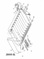
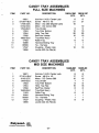
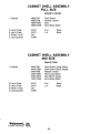
CANDY TRAY ASSEMBLIES
FULL SIZE MACHINES
--/'
ITEM
1
2
3
4
5
6
7
8
9
10
11
12
PART NO.
DESCRIPTION
18821
ST-2614-BLK
17595-3DC
18162-3CC
17843-BLK
17853
17854
17858
18820-BLK
17403
18389
80569
17537
13856
Nut-Hex 1/4-20, Center Lock
Screw - #8-18 x 1/2
Motor - DC (360 Degree Cam)
Motor - DC Cainca 360
Tray Divider
Tray Filler Bottom
Helix Tray Rail
Sel/Price Holder
Tray-Weld Ass'y
Roller-Tray
Harness-Sliding Tray
Tie - Harness
Coupling - Plastic Hub
Loctite 422 (As Req'd)
18818·10M
QTY.
18818·10C
QTY.
6
6
21
10
21
9
10
20
10
1
10
9
10
20
10
1
6
6
1
1
10
1
1
10
CANDY TRAY ASSEMBLIES
MID SIZE MACHINES
ITEM
1
2
3
4
5
6
7
8
9
10
11
12
PART NO.
18821
ST-2614-BLK
18162-3CC
17843-BLK
17853
17854
17858
18483-BLK
17403
18484
80569
17537
13856
""IJ~~ndlMC
CONWAY. ARKANSAS
DESCRIPTION
Nut-Hex 1/4-20, Center Lock
Screw - #8-18 x 1/2
Motor - DC Cainca 360
Tray Divider
Tray Filler Bottom
Helix Tray Rail
Sel/Price Holder
Tray-Weld Ass'y
Roller-Tray
Harness-Sliding Tray
Tie - Harness
Coupling - Plastic Hub
Loctite 422 (As Req' d)
fiJR.
li{J1©
-37-
18486·8M
QTY.
18486·8C
QTY.
6
17
10
7
8
16
6
17
10
7
8
8
1
6
1
1
1
6
1
1
8
8
8
16
l'''IJ\1end.c JiJl:l...
CONWAY.ARKANSAS
liI}1©
-38-
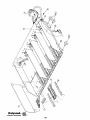
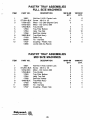
PASTRY TRAY ASSEMBLIES
FULL SIZE MACHINES
ITEM
1
2
3
4
5
6
7
8
9
11
12
PART NO.
18821
ST-2614-BLK
17595-3DC
18162-3CC
17843-BLK
17853
17854
17858
18820-BLK
17403
80569
17537
13856
DESCRIPTION
18818-5M
QTY.
18818-5C
QTY.
6
11
5
6
11
Nut-Hex 1/4-20, Center Lock
Screw - #8-18 x 1/2
Motor - DC (360 Degree Cam)
Motor - DC Cainca 360
Tray Divider
Tray Filler Bottom
Helix Tray Rail
Sel/Price Holder
Tray-Weld Ass'y
Roller-Tray
Tie - Harness
Coupling - Plastic Hub
Loctite 422 (As Req' d)
4
5
10
5
1
6
1
5
5
4
5
10
5
1
6
1
5
18486-4M
QTY.
18486-4C
QTY.
6
9
5
6
9
5
3
4
8
4
1
6
1
4
PASTRY TRAY ASSEMBLIES
MID SIZE MACHINES
ITEM
PART NO.
1
2
3
4
5
6
7
8
9
11
12
18821
ST-2614-BLK
18162-3CC
17843-BLK
17853
17854
17858
18483-BLK
17403
80569
17537
DESCRIPTION
Nut-Hex 1/4-20, Center Lock
Screw - #8-18 x 1/2
Motor - DC Cainca 360
Tray Divider
Tray Filler Bottom
Helix Tray Rail
Sel/Price Holder
Tray-Weld Ass'y
Roller-Tray
Tie - Harness
Coupling - Plastic Hub
""IJ~endlllr. fill<.
CONWAY. ARKANSAS ~©
-39-
3
4
8
4
1
6
1
4
r
/
a
~
.
\
.
\
tp
~
t.®
"LT51l ""~~
uSEO
.... 6..cv 0 '
.~ #"4.01""C
.,...... 'DAy.A.
<!bIG
- /•
DI'AVll!"
,,"--r
~sc.,r«-
L~O
.. boiS
~
1
DETAIL
-;.,-
e
P"IJ,,~nd~
CONWAY. ARKANSAS
fiJ:l<.
l:t(Jf©
--
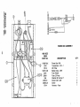
SLIDING DRAWER PART NO. --ITEM
PART
DESCRIPTION
17922-56B
4
4
4
6
17958-BLK ESCUTCHEON-MID DRAWER
b
"
6
6
6
- 14
- 15
16
18
18
20
21
:'Ir:
-.... i.i.
~1'
J. ..J
24
2S
26
27
28
29
32
34
7r:
..hJ
36
37
39
40
4">..
43
--45
- 45
47
49
eli
J.t.
53
54
55
56
57
63
64
65
QTY
18041-TVC 18041-TNC
GTY
DTY
GTY
IB041-WTV
IlTY
1B041-ltlTO
aTY
DRAWER WiA SLIDIN6
1
6
--
~m.
IB041-CVC 18041-CNC
17959-6TD ESCUTCHEON-MID DRAWER
17959-6TO ESCUTCHEON-"ID DRAWER
IBOb9
DECAL - ESCUTCHEON
18069-BWH DECAL - ESCUTCHEON
18069-BWD DECAL - ESCUTCHEON
lS0b9-CWQ DECAL - ESCUTCHEON
IB069-RWH DECAL - ESCUTCHEON
IB069-TWQ DECAL - ESCUTCHEON
IB069-TWV DECAL - ESCUTCHEON
17904
SCAVENGE SUDE
17901
HOLDER SCAVENSE SLIDE
17948
INSERT COIN -US
17916-BLK CAP - MID-ESCUTCHEON
17916-8T CAP - MID-ESCUTCHEON
17310
LENS - READOUT
1
18039-BLK INSERT - VALIDATOR
1
18274-A)E BUTTON-SELECTION
(SEn
17771-BLK BRACKET-VALIDATOR MTG.
1
18144-BLK RETAINER-VAL. INSERT
2
180b3-BLK BRACKET-COIN CHUTE
1
17804
REAR - COiN CHUTE
17803
COVER - COIN CHUTE
18034
VALIDAiOR - MAKA 24V
I
18027-CA BRACKET ASS'y - JONES
1
17S78-eA KEY PAD - CA
1
17798-BLK PLATE - SCAVENGE
1
LINK - SCAVENGE
17800
1
810-00 STRIP-NEOPRENE (2.8ft)
1
CONTF:OLLER - CA
17656
1
SUPPORT - CIRCUIT BD
11808
4
17654-CA CABLE-KEY PAD EXT.
1
1
17907
CABLE DISPLAY
17928
HARNESS - POWER
1
17700
GRAPHICS READOUT-LCD
DISPLAY CA - LCD
1
17937
17977-CA HARNESS CA - "AKA
1
17390
DECAL - CAUTION
1
13140
SCREW 110 PAN
7
I29B-BLK SCREW 18 PAN
11
186B-BLK SCREW 18 PAN
5
11894
SCREW #s
3
17902
HARNESS-INTERCONNECT
1
IB145-B[i( FILLER-VALIDATOR
EXTENSION SPRING
611
8538-02 CLAMP-HARNESS
2
8538-01 CLA"P-HARNESS
1
1
1
1
1
1
(SET) 1
©
1
(SET) 1
(SET) 1
(SET) 1
1
1
.
'j
2
1
1
1
1
1
1
1
1
4
1
1
1
4
1
1
1
4
1
4
1
1
1
1
1
4
1
1
1
1
1
1
7
6
5
5
3
5
3
6
5
5
3
1
1
1
1
6
5
7
5
11
1
1
1
1
1
"•
1
1
l'olJcend..., ~
CONWAY. ARKANSAS
1
(SET)
-41-
1
1
11
5
3
3
1
1
1
1
2
1
1
1
A
0
~-a
~G
-<-
B
C
..
I
D
: E
._,..... '-F
Q
H
J
7
"
.~
~Il
p\
~~
~:z
-to
~c.
I.n ~
>-
F
•
",",v\.1'
€@
II
10
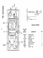
POWER BOX ASSEMBLY
FULL SIZE
18013
PART NO.
17987-BLK
17729
17913
17915-120
2091
2086-1
266
2050-21
1298-BLK
17914
DESCRIPTION
Power Box WIA
Transformer - 24V - 1
RFI Filter
Ballast Assy, 120V
Fuse Holder
Fuse 2.0 Amp
Washer #8 Internal T
Screw 6-32 x 3/8
Screw
Harness - Fuse
Cry
1
1
1
1
1
1
1
2
8
1
6
5
S
STAIt.Tt~
POWER BOX ASSEMBLY
I
~
~
MID SIZE
I
18868
PART NO.
I
I
10
I
17987-BLK
17941
17913
18870-120
2091
2086-1
266
2050-21
1298-BLK
17914
QTY
DESCRIPTION
1
1
1
1
1
Power Box WIA
Transformer - 24V - 1
RFI Filter
Ballast Assy, 120V
Fuse Holder
Fuse 2.0 Amp
Washer #8 Internal T
Screw 6-32 x 3/8
Screw
Harness - Fuse
1
1
2
8
1
I
I
I
I
(
1\1
)-0
"i
.....
bilE
I
)0-
I
I
I
-----i!.u""~1J
I
o
I
I
I
I '
POWER BOX ASSEMBLY
,6
I
~
0'1
I
.
R.Ji
FULL SIZE
18011
PART NO.
4f
II .
I
I
10
17987-BLK
17941
17913
17915-120
2091
2086-1
266
2050-21
1298-BLK
17914
DESCRIPTION
Power Box WIA
Transformer - 24V - 1
RFI Filter
Ba.llast Assy, 120V
Fuse Holder
Fuse 2.0 Amp
Washer #8 Internal T
Screw 6-32 x 3/8
Screw
Harness - Fuse
QTY
1
1
1
1
1
1
1
2
8
1
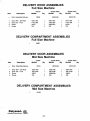
DELIVERY DOOR ASSEMBLY
DELIVERY COMPARTMENT
(/'
.....
~/-1I
I
I
I
I
I
I
r
l'''I)r~endllle fi1tL
liflf©
CONWAY. ARKANSAS
-46-
I
DELIVERY DOOR ASSEMBLIES
Full Size Machine
,-----
.... ~
Item
Description
Door Assembly-Delivery
1
2
3
4
Door W/A - Del Rear
Door Del - Front
Decal
Rivets
"Push"
Blk/Blk
Qty
18042
18031-Blk
17931-Blk
18037
729
1
1
1
4
"Press Here"
Qty
Blk/Blk
"Press Here"
Qty
Brn/Blk
18042-Blk
18042-DB
18031-Blk
17931-Blk
18093-Blk
729
1
1
1
4
18031-Blk
17931-DB
18093
729
1
1
1
4
DELIVERY COMPARTMENT ASSEMBLIES
Full Size Machine
18687
DELIVERY DOOR ASSEMBLIES
Mid Size Machine
Item
Description
Door Assembly-Delivery
1
2
3
4
Door W/A - Del Rear
Door Del - Front
Decal
Rivets
"Push"
Blk/Blk
Qty
18516
18031-Blk
18512-Blk
18037
729
1
1
1
4
"Press Here"
Blk/Blk
Qty
"Press Here"
Qty
Brn/Blk
18516-Blk
18516-DB
18031-Blk
18512-Blk
18093-Blk
729
1
1
1
4
18031-Blk
18512-DB
18093
729
DELIVERY COMPARTMENT ASSEMBLIES
Mid Size Machine
18492
l'''I,~end~ Jill<.
CONWAY. ARKANSAS
~©
-47-
1
1
1
4
,
----
@.
~
@,
"
.
~
®
./ij
i
1 .,
j.
1/'/:
"',-@
1/
"
.' •...'
.'
•
rot
I~
1/:/,... I
.~
0
I
.1,' :
I
.. . .
i"o~:
.1:/•
; /,
..
'0
o.
@
@~
~t
.
·S,
7
.......
1
@
@
For use with P.P. 49, 50 & 51
l'''IJ~~nd
INC
fiJR.
CONWAV.ARKANSAS ~©
-48-
-
I~
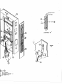
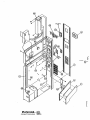
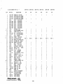
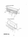
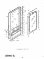
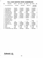
FULL SIZE SERVICE DOOR ASSEMBLIES
Item
Description
Door Assembly-Service
Part No.
Qty Part No.
18040-0B
Qty. Part No.
18040-REO
Qty. Part No.
18040-TRA
18040-SGB
(CONTEMP)
"-/'
1
2
3
4
5
6
7
8
9
10
11
12
13
13
13
16
17
18
19
20
21
22
23
24
Door W/A-Service
Holder-Glass-Top
Holder-Glass-LH
Holder-Glass-RH
Glass-Service Ooor
Gasket-Service Ooor
Lock Asy-Srvc Door
Cam-Lock, Service
Bar W/A-Locking
Trim-LS & RS Ooor
Trim - Ooor-Top & BTM
Trim-Del Camp. Mid
Panel-Clear, Lower
Panel-Walnut, Service
Panel Blk. Lower SO
Screw #10-24
Panel-Oecor R.H.
Panel-Decor L.H.
Hinge-Service Ooor
Screw
Screw
Rivet
Retaining Plug
Trim-Service Ooor Hinge
P"I~~~nd..c.
CONWAY. ARKANSAS
17924-0B
17934-BLK
17954-BLK
17954-BLK
18222
17970
14325-BLK
17457-BLK
18001-BLK
17956-0B
17957-0B
17967-0B
18102
1
1
1
1
1
12
1
1
1
2
2
2
1
17924-RED
17934-BLK
17954-BLK
17954-BLK
18221
17970
14325-BLK
17457-BLK
18001-BLK
17955-BLK
17957-BLK
17967-BLK
1
1
1
1
1
12
1
1
1
2
2
2
17924-0B
17934-BLK
17954-BLK
17954-BLK
18222
17970
14325-BLK
17457-BLK
18001-BLK
17956-GT
17957-GT
17967-GT
Qty.
1
1
1
1
1
12
1
1
1
2
2
2
17924-SGB
17934-BLK
17954-BLK
17954-BLK
18221
17970
14325-BLK
17457-BLK
18001-BLK
17956-GT
17957-GT
17967-GT
1
1
1
1
1
12
1
1
1
2
2
2
2
1
1
1
11
22
18
1
1
18288
746
17932-BLK
17933-BLK
18774-SGB
1868-BLK
18033
729
18442
18873-SGB
1
2
1
1
1
11
22
18
1
1
9100-06
746
17932-0B
17933-0B
18774-0B
1868-BLK
18033
729
18442
18873-0B
2
1
1
1
11
22
18
1
1
746
17932-BLK
17933-BLK
18774-REO
1868-BLK
18033
729
18442
18873-RED
fiJl:l...
~©
-49-
2
1
1
1
11
19
18
1
1
746
17932-0B
17933-0B
18774-0B
1868-BLK
18033
729
18442
18873-0B
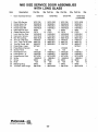
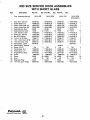
MID SIZE SERVICE DOOR ASSEMBLIES
WITH LONG GLASS
Item
Description
Door Assembly-Service
1
2
3
4
5
6
7
8
9
10
11
12
13
13
16
17
18
19
20
21
22
23
24
Door W/A-Service
Holder-Glass-Top
Holder-Glass-LH
Holder-Glass-RH
Glass-Service Door
Gasket-Service Door
Lock Asy-Srvc Door
Cam-Lock, Service
Bar W/A-Locking
Trim-LS & RS Door
Trim - Door-Top & BTM
Trim-Del Compo Mid
Panel-Clear, Lower
Panel-Walnut Service
Screw #10-24
Panel-Decor R.H.
Panel-Decor L.H.
Hinge-Service Door
Screw
Screw
Rivet
Retaining Plug
Trim-Serv Door Hinge
Part No.
Qty Part No.
Qty. Part No.
18759-RED
18759-DB
Qty. Part No.
18759-TRA
18759-SGB
(CONTEMP)
18721-DB
18499-BLK
17954-BLK
17954-BLK
18760
17970
14325-BLK
17457-BLK
18001-BLK
17956-GT
18501-GT
18502-GT
18778-01
1
1
1
1
1
12
1
1
1
2
2
2
1
18721-RED
18499-BLK
17954-BLK
17954-BLK
18761
17970
14325-BLK
17457-BLK
18001-BLK
17955-BLK
18501-BLK
18502-BLK
1
1
1
1
1
12
1
1
1
2
2
2
18721-DB
18499-BLK
17954-BLK
17954-BLK
18760
17970
14325-BLK
17457-BLK
18001-BLK
17956-GT
18501-GT
17967-GT
1
1
1
1
1
12
1
1
1
2
2
2
746
17932-DB
17933-DB
18774-DB
1868-BLK
18033
729
18442
18873-DB
2
1
1
1
11
22
18
1
1
746
17932-BLK
17933-BLK
18774-RED
1868-BLK
18033
729
18442
18873-RED
2
1
1
1
11
19
18
1
1
9100-08
746
17932-DB
17933-DB
18774-DB
1868-BLK
18033
729
18442
18873-DB
1
2
1
1
1
11
19
18
1
1
I'QIJ~~nd-.r. ~
CONWAY. ARKANSAS ~©
-50-
Qty.
18721-SGB
18499-BLK
17954-BLK
17954-BLK
18761
17970
14325-BLK
17457-BLK
18001-BLK
17956-GT
18501-GT
18502-GT
18778-01
1
1
1
1
1
12
1
1
1
2
2
2
1
746
17932-BLK
17933-BLK
18774-SGB
1868-BLK
18033
729
18442
18873-SGB
2
1
1
1
11
22
18
1
1
/
/
(
.
MID SIZE SERVICE DOOR ASSEMBLIES
WITH SHORT GLASS
Item
Description
Door Assembly-Service
I
I
1
2
3
4
5
6
7
8
9
10
11
12
13
13
16
17
18
19
20
21
22
23
24
Door W/A - Service
Holder-Glass-Top
Glass Holder-Side LH
Glass Holder-Side RS
Glass-Service Door
Gasket-Service Door
Lock Asy-Srvc Door
Cam-Lock, Service
Bar W/A-Locking
Trim-LS & RS Door
Trim - Door-Top & BTM
Trim-Del Camp. Mid
Panel-Clear, Lower
Panel-Walnut, Service
Screw #10-24
Panel-Decor R. H.
Panel-Decor L. H.
Hinge-Service Door
Screw
Screw
Rivet
Retaining Plug
Trim-Serv Door Hinge
1'"IJ~~ndllC
Part No.
aty Part No.
18510-DB
aty. Part No.
aty.
18510-SGB
(CONTEMP)
18510-TRA
18510-RED
18508-DB
18499-BLK
18504-BLK
18504-RBK
18500
17970
14325-BLK
17457-BLK
18509-BLK
17956-GT
18501-GT
18502-GT
18778-00
1
1
1
1
1
12
1
1
1
2
2
2
1
18508-RED
18499-BLK
18504-LBK
18504-RBK
18762
17970
14325-BLK
17457-BLK
18509-BLK
17955-BLK
18501-BLK
18502-BLK
1
1
1
1
1
12
1
1
1
2
2
2
18508-DB
18499-BLK
18504-LBK
18504-RBK
18500
17970
14325-BLK
17457-BLK
18509-BLK
17956-GT
18501-GT
18502-GT
1
1
1
1
1
12
1
1
1
2
2
2
746
17932-DB
17933-DB
18774-DB
1868-BlK
18033
729
18442
18873-DB
2
1
1
1
11
22
18
1
1
746
17932-BLK
17933-BlK
18774-RED
1868-BlK
18033
729
18442
18873-RED
2
1
1
1
11
19
18
1
1
9100-07
746
17932-DB
17933-DB
18774-DB
1868-BlK
18033
729
18442
18873-DB
1
2
1
1
1
11
22
18
1
1
JiJR.
CONWAY. ARKANSAS ~©
-51-
18508-SGB
18499-BLK
18504-LBK
18504-RBK
18500
17970
14325-BLK
17457-BLK
18509-BLK
17956-GT
18501-GT
18502-GT
18878-00
1
1
1
1
1
12
1
1
1
2
2
2
1
746
17932-BLK
17933-BlK
18774-SGB
1868-BlK
18033
729
18442
18873-SGB
2
1
1
1
11
19
18
1
1
",
""IJ~~nd-: JiJR.
CONWAY. ARKANSAS
.li[Jf©
-52-
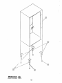
CABINET SHELL ASSEMBLY
FULL SIZE
SPECIFY COLOR
1 Cabinet
18862-DB
18862-WB
18862-RED
18862-SGB
Dark Brown
Wittenb' Brown
Red
Semi-Gloss Black
2
3
4
5
18747
18747
318
12766
R.H.
L.H.
Leg & Plate
Leg & Plate
Screw 1/4-20
Leg Equalizer
Black
Black
CABINET SHELL ASSEMBLY
MID SIZE
Specify Color
1 Cabinet
18497-DB
18497-DBS
18497-WB
18497-RED
18497-RDS
: 8497-SGB
Dark Brown (Long Glass)
Dark Brown (Short Glass)
Wittenb' Brown
Red (Long Glass)
Red (Short Glass)
Semi-Gloss Black
2
3
4
5
18747
18747
318
12766
R.H.
L.H.
Leg & Plate
Leg & Plate
Screw 1/4-20
Leg Equa.lizer
l'''IJ~end.c.fiJR.
CONWAY. ARKANSAS ~©
-53-
Black
Black
RACK MODULE ASSEMBLY
ITEM
PART NO.
NOMENCLATURE
1
2
10484-01
18068
3
12287-01
Rack Module Assembly
Decals - Selection Number (Complete
set numbers 1 thru 20)
Tab and Stripper Assembly - Plastic
""IJ~end..e ~
li[J1©
CONWAY. ARKANSAS
-54-
MODULE ARM COMPLETE 17777-BLK
ITEM
PART NO.
NOMENCLATURE
1
2
3
4
10483-BLK
1298
17595-1 DC
1868
5
17658-BLK
Module Arm
Screw #8-18 x 3/8"
Motor Assembly - Complete D.C. (180° cam)
Screw - #8-32 x 1/4 Type (4 ea.)
B Pan Hd Ph Recess
ZPYD
Plate, Mounting
l''II'~8nd~ ~
CONWAV.ARKANSAS ~©
-55-
-56-
RACK MODULE - 8-10484
ITEM
,r,~·
~'
1
2
3
4
5
6
7
8
9
10
11
12
13
14
15
16
PART NO.
NOMENCLATURE
10495-01
730
729
2559
2558
1744
2565
1774
1741
1642
1743
1178
1745
2563
1869
10487
Slidt:' & Module Assembly
Bushing
"Pop" Rivet SD-42-BS
"E" Ring, Tru Arc
Front Sprocket Shaft
Spring Lock
Sprocket - Front
Chain Guide
Sprocket Shaft - Rear
"Pop" Rivet SD-45-BS
Spring, Rear Sprocket, Detent
Bearing Bushing
Spacer - Detent, Spring "T"
Sprocket - Rear
Spacer - Detent, Spring "Plain"
Cha.in Assy., Complete - Wedge
I'QIJ~8ndllC liP<.
CONWAY. ARKANSAS
liI)!©
-57-
-- ------ -----
CHAIN SEGMENT ASSEMBLY A-10416
ITEM
1
2
3
4
5
PART NO.
NOMENCLATURE
A-1720
A-1754
0-1723
C-1717
C-1719
Spring Compression
Wedge, Cylindrical (2 req)
Chain Housing Segment
Slide
Lifter, Cylinder
.,,,IJ~~nd-. Jill<..
CONWAY. ARKANSAS
~©
-58-
.~ p
..
,
-
\
DoIJ.sltll...c.
1IoIy\141nd
700 South German Lane
Conway, Ark. 72032 USA
Phone (501) 327,1301
700 South German Lane
Conway, Ark. 72032 USA
INT.
Phone~0\)32n1301
T elax 536237 USA
PIN 8935 PI'
. . . .HlldLTlJ.
Station La ne
Witney, Oxon OXB 6BU England
. Phone (084 421) 3453
Telex 837534
Printed in USA