1
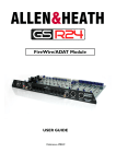
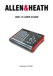
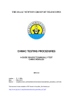
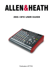
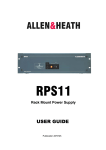
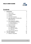
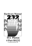
Analogue Interface Module
USER GUIDE
Publication AP8348
Limited One Year Manufacturers Warranty
This product is warranted to be free from defects in materials or workmanship for period of one year from the date
of purchase by the original owner.
To ensure a high level of performance and reliability for which this equipment has been designed and manufactured,
read this User Guide before operating.
In the event of a failure, notify and return the defective unit to the place of purchase.
If this is not possible then please contact the authorised ALLEN & HEATH distributor or agent in your country as
soon as possible for repair under warranty subject to the following conditions.
Conditions of Warranty
The equipment has been installed and operated in accordance with the instructions in this User Guide.
The equipment has not been subject to misuse either intended or accidental, neglect, or alteration other than as
described in the User Guide or Service Manual, or approved by ALLEN & HEATH.
Any necessary adjustment, alteration or repair has been carried out by an authorised ALLEN & HEATH distributor or
agent.
This warranty does not cover fader wear and tear.
The defective unit is to be returned carriage prepaid to the place of purchase, an authorised ALLEN & HEATH distributor or agent with proof of purchase.
Please discuss this with the distributor or the agent before shipping.
If the unit is to be repaired in a different country to that of its purchase the repair may take longer than normal,
whilst the warranty is confirmed and parts are sourced.
Units returned should be packed to avoid transit damage.
In certain territories the terms may vary. Check with your ALLEN & HEATH distributor or agent for any additional
warranty which may apply.
If further assistance is required please contact Allen & Heath Ltd.
IMPORTANT- PLEASE READ CAREFULLY:
By using this Allen & Heath product and the software within it, you agree to be bound by the terms
of the relevant End User Licence Agreement (EULA), a copy of which can be found on the Allen & Heath
website in the product's pages. You agree to be bound by the terms of the EULA by installing, copying,
or otherwise using the software.
This product complies with the European Electromagnetic Compatibility directive 2004/108/EC
and the European Low Voltage Directive 2006/95/EC.
This product has been tested to EN55103 Parts 1 & 2 1996 for use in Environments E1, E2, E3, and E4 to
demonstrate compliance with the protection requirements in the European EMC directive 2004/108/EC.
During some tests the specified performance figures of the product were affected. This is considered
permissible and the product has been passed as acceptable for its intended use. Allen & Heath has a strict
policy of ensuring all products are tested to the latest safety and EMC standards. Customers requiring more
information about EMC and safety issues can contact Allen & Heath.
NOTE: Any changes or modifications to the console not approved by Allen & Heath could
void the compliance of the console and therefore the users authority to operate it.
GS-R24 Analogue Interface Module User Guide AP8348 Issue 1
Copyright © 2011 Allen & Heath Limited. All rights reserved
Allen & Heath Limited
Kernick Industrial Estate, Penryn, Cornwall, TR10 9LU, UK
http://www.allen-heath.com
Allen & Heath
3
GS_R24 Analogue Module User Guide
PACKED ITEMS
Check that you have received the following:
ALLEN&HEATH
MIDI OUT
MIDI IN
ANALOGUE INPUTS 1-32
ANALOGUE OUTPUTS 1-32
ANALOGUE
I/O Module
GS-R24 ANALOGUE INTERFACE MODULE
Also Packed in the box
Allen & Heath
•
Safety Instructions—English
•
Safety Instructions—French
•
Addendum note ROHS
•
Sticker
•
This User Guide
4
GS_R24 Analogue Module User Guide
CONTENTS
Thank you for purchasing your Allen & Heath GS-R24 Analogue interface module. To
ensure that you get the maximum benefit from the unit please spare a few minutes
familiarizing yourself with the features and setup procedures outlined in this user guide.
For further information please refer to the additional information available on our web
site, or contact our technical support team.
http://www.allen-heath.com
This User Guide is to be read in conjunction with the GS-R24 console user
guide AP7784 in order to understand the routing of the interface signals to and
from the analogue system in the console. Also, some setup guides are
included on the Website for Digital Audio Workstations (DAWs). Please check
our website or with Tech Support for further information and setup guides.
Allen & Heath
Warranty ...........................................................
3
Packed Items .....................................................
4
Contents ............................................................
5
Specifications .....................................................
6
Fitting Instructions .............................................
7
Analogue In/Out Connector Pin Numbers ............
8
Connector Cable Notes .......................................
8
Module Panel Features........................................
9
Product Support .................................................
10
Registration .......................................................
10
5
GS_R24 Analogue Module User Guide
GS-R24 ANALOGUE MODULE SPECIFICATIONS
General Specifications
Number of audio channels Output
32
Number of audio channels Input
32
Nominal Signal Level
0dBu
Analogue signal connector type
37 pin D sub
MIDI Input
5pin DIN
MIDI Output
5pin DIN
Headroom
Digital domain headroom (nominal to 0dBFS)
21dB
Channel Mapping to Interface
Console Channels
Interface Channels
Mono Channels 1-24
1-24 *
Stereo Channel 1
25-26 (L-R)
Stereo Channel 2
27-28 (L-R)
Valve Channel 1
29
Valve Channel 2
30
Main Stereo (2 Track 1) out and DIG Master L-R in.
31-32 (L-R)
* The interface sends 17-24 can be switched from Mono channels 17-24 to Aux 1-4 and Groups 1-4 in order to
record or process summed or grouped signals. This is done by pressing the under-panel switch on the GS-R24
labelled 17-24=Aux+Grp.
Allen & Heath
6
GS_R24 Analogue Module User Guide
MODULE FITTING INSTRUCTIONS
Beware of ESD! Observe anti-static handling precautions—avoid touching the electronic devices on
the circuit board, ensure any static build up is discharged to earth before handling the module.
This can be achieved by ensuring the console is connected to the psu and the psu is plugged in to a
mains outlet but switched OFF, then touching a metal part of the console panel such as a screw head.
Remove the blanking panel at the
rear of the console by removing
the two screws.
Remove 2 x screws
Locate the module circuit board
in the plastic guide slots within
the housing.
Slide the module into the housing
and push firmly to insert the
module connectors into the console connector sockets.
Re-fit the fixing screws at either
end of the module panel.
Push
To remove the module for any reason, the easiest way is to unscrew and remove the fixing screws at each end of the panel
then use the D Sub cable connectors to gently pull out the module. A small side to side rocking action will help to displace
the circuit board connectors from the internal mother-board.
Allen & Heath
7
GS_R24 Analogue Module User Guide
37 PIN D TYPE CONNECTOR PINNING
Analogue Input & Output 37 way D connector pin ident.
19
1
37
20
Pin assignment (Input or Output connectors)
PIN No.
1
Designation
CHASSIS
2
CHANNEL 2
3
CHANNEL 4
4
CHANNEL 6
5
CHANNEL 8
6
CHANNEL 10
7
CHANNEL 12
8
CHANNEL 14
9
CHANNEL 16
10
CHANNEL 18
11
CHANNEL 20
12
CHANNEL 22
13
CHANNEL 24
14
CHANNEL 26
15
CHANNEL 28
16
CHANNEL 30
17
CHANNEL 32
18
SIGNAL 0V
19
20
CHASSIS
CHANNEL 1
21
CHANNEL 3
22
CHANNEL 5
23
CHANNEL 7
24
CHANNEL 9
25
CHANNEL 11
26
CHANNEL 13
27
CHANNEL 15
28
CHANNEL 17
29
CHANNEL 19
30
CHANNEL 21
31
CHANNEL 23
32
CHANNEL 25
33
CHANNEL 27
34
CHANNEL 29
35
CHANNEL 31
36
SIGNAL 0V
37
SIGNAL 0V
Allen & Heath
View of rear connector.
Observe pin numbering
of connector to be
wired.
Connection guidelines & notes
The type of connection cable you will need depends on
the type of equipment you are using. For this reason
we do not supply cables with the module—they would
almost definitely need customising.
Connection cables can be made up at service centres
or by a competent practical minded person such as a
studio engineer!
We can offer ready made 37way D sub cables—please
check with your Allen & Heath sales representative or
on our website.
To achieve the channel count, the analogue signals are
unbalanced. To ensure best performance when connected to external equipment here are some guidelines
to follow when wiring the cables.
1)
Be aware that both input and output connectors
on the module are female. This is deliberate to
minimise the risk of damaged pins on the module. The cable connectors will be male for both
input & output ports on the module. Ensure
these are plugged in the correct position—it is
sensible to colour code them!
2)
If the source equipment has balanced outputs,
connect the -ve phase to SIGNAL 0V on the
module.
3)
If the source equipment is unbalanced, connect
the 0V of the source equipment to SIGNAL 0V.
4)
Connect CHASSIS from the module to the chassis connection of the external equipment.
5)
If the external equipment input circuitry is balanced, connect the –ve (or cold) pin of each input to SIGNAL 0V on the module.
6)
If the external equipment input circuitry is unbalanced, connect the 0V of the external equipment
to SIGNAL 0V on the module. Ideally this will be
separate to Chassis.
Please refer to the allen-heath.com website for
more information and connection details.
8
GS_R24 Analogue Module User Guide
MODULE PANEL FEATURES
ALLEN&HEATH
MIDI OUT
MIDI IN
ANALOGUE INPUTS 1-32
ANALOGUE OUTPUTS 1-32
ANALOGUE
I/O Module
MIDI Input & Output
Standard 5 pin DIN MIDI connectors. The MIDI OUT carries the MIDI data
generated by the MIDI controllers and switches on the GS-R24.
The MIDI IN is the MIDI data required to illuminate LEDs and provide moving fader information to the console.
The MIDI IN connector can also be used for programming the operating
firmware in the console.
ANALOGUE INPUTS 1-32
Standard 37 pin D Subminiature type connector. These are the analogue
signals (unbalanced) which provide the GS-R24 with playback from the multitrack recording medium. This could be in the form of external Digital to
Analogue converters (DACs) or an analogue source such as a tape machine
output.
ANALOGUE OUTPUTS 1-32
Standard 37 pin D Subminiature type connector. These are the analogue
signals (unbalanced) which are sent from the GS-R24 to the multi-track recording medium. This could be in the form of external Analogue to Digital
converters (ADCs) or an analogue system such as a tape machine.
Allen & Heath
9
GS_R24 Analogue Module User Guide
PRODUCT SUPPORT
Investigate ALLEN & HEATH’s other ranges at www.allen-heath.com
Large Live Sound mixers — iLive digital, and GL Series
Small Format Live Sound mixers — ZED, MixWizards and PA Series
DJ products — Xone Series
Sound Management Series — iDR Series
Registering your product
Thank you for buying the Allen & Heath GS-R24 module. We hope that you are happy with it and that you enjoy many years
of faithful service with it, and record and mix some great music.
Please go to www.allen-heath.com/register.asp and register your product’s serial number and your details. By registering with
us and becoming an official Registered User, you will ensure that any warranty claim you might make is actioned quickly and
with the minimum delay.
Alternatively, you may either copy or cut off this section of the page, fill in the details, and return it by mail to:
Allen & Heath Ltd, Kernick Industrial Estate, Penryn, Cornwall TR10 9LU, UK
Product Support: You can access Allen & Heath Tech Support by logging on to www.allen-heath.com/support
Allen & Heath
10
GS_R24 Analogue Module User Guide