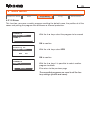
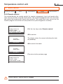
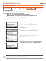
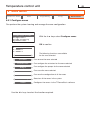
1
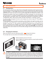
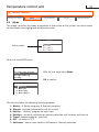
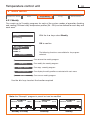
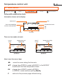
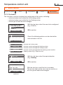
11/09-01 PC Installation manual item HC/HS/HD 4695 L/N/NT 4695 AM 5875 Temperature control unit CONTENTS 1 INTRODUCTION 5 1.1 Warnings and tips 5 1.2 Content of the package 5 2 DESCRIPTION OF THE CONTROL UNIT 6 2.1 General features 6 2.2 The front 7 2.3 The main screen 2.4 Mode of operation 3 INSTALLATION 8 11 12 3.1 Configuration 13 3.2 Changing the batteries 13 4 SWITCHING ON FOR THE FIRST TIME 15 5 MAIN MENU 16 5.1 Visualize zones 17 5.2 Mode 18 5.2.1 Weekly 19 5.2.2 Manual 19 5.2.3 Holiday 20 5.2.4 Holidays 21 5.2.5 Timed 22 5.2.6 OFF 22 5.2.7 Antifreeze / Thermal protection 22 5.3 Programming 23 5.3.1 Weekly 24 5.3.2 Holiday32 Temperature control unit CONTENTS 5.4 Setup35 5.4.1 Summer/Winter36 5.4.2 Temperature37 5.4.3 Date/Time38 5.4.4 Standard time39 5.4.5 Remote control 40 5.4.6 Contrast 41 5.4.7 Screen saver 42 5.4.8 Language 43 5.4.9 External temperature 44 5.5 Maintenance 45 5.5.1 Configure zones 46 5.5.2 Diagnostic 56 5.5.3 Probe setting 59 5.5.4 System test 60 5.5.5 Total reset 61 TECHNICAL DATA 62 TROUBLESHOOTING 63 1 INTRODUCTION 1.1 Warnings and tips Before proceeding with the installation this manual should be read carefully, because the guarantee is automatically cancelled in the event of negligence, incorrect manoeuvre or improper use or if unauthorised people tamper with the circuit. Moreover it is cancelled when the fault is due to strong accidental overvoltages on the power supply network. Thus if the Control Unit is installed in a place which is subject to violent atmospheric discharges (storms), suitable protection must be installed on the power supply line and it must be connected to the earth as rigorously as possible, in accordance with local regulations. 1.2 Content of the package • Temperature Control unit item 4695 • Temperature Control unit user manual • CD-ROM containing: Temperature Control unit installation manual TiThermoBasic software TiThermoBasic user manual Temperature control unit 2 DESCRIPTION OF THE CONTROL UNIT 2.1 General features The temperature control unit item 4695 is a control and adjustment device for My Home temperature control systems. It can be used with heating and air conditioning systems. It can control systems with up to 4 zones, one of which is directly controlled (LOCAL ZONE). It enables setting of the system’s parameters and modification of the operating modes. Operation software is also included, with menus displayed on the backlit screen. The user can display the state and temperature of the zones, select the operating mode, display and set the daily temperature profiles as well as the weekly and holidays programs parameters. The zones can also be configured, and diagnostics for the whole system can be carried out. The temperature control unit is made up of a fixed base connected to the system bus and with pull-off front, to let the user program it and change the batteries more easily. The Control panel must be configured by installing the configurators in their seats (see 3.1 Configuration); programming and configuration of the system can be done using the TiThermoBasic software in the CD supplied. 2 DESCRIPTION OF THE CONTROL UNIT 2.2 The front 1 2 7 3 C 6 OK 5 4 1 -Graphic display: displays the messages which guide the programming operations and the system state. 2 -É selection key: while the main screen is displayed, when the local zone manages fancoil actuators it can cycle between the operation speeds; inside the menu it can scroll any functions to the left. 3 -Ñ selection key: while the main screen is displayed, when the local zone manages fancoil actuators it can cycle between the operation speeds; inside the menu it can scroll any functions to the right. 4 -OK key: enters the main menu, confirms the displayed selection or the entered data. 5 -Sensor: measures the temperature of the local probe. 6 -C key: cancels the selection and returns to the previous page. Keep it pressed to return to the main screen. 7 - ÅÇ scroll keys: these let you change the set temperature while the main screen is being viewed just on the local zone; when inside the menu, you can scroll the list of the options available. Temperature control unit 2 DESCRIPTION OF THE CONTROL UNIT 2.3 The main screen In the idle conditions a screensaver, which can be selected by the user among the ones installed, will be displayed. Press any key to switch the display on and display the main screen. Background information During normal operation the display shows the following information: Load state ON/OFF Expected temperature System state Winter/Summer Temperature measured Weekly program Mode set information Date/Time Depending on the set mode, the temperature of the whole profile (weekly or holiday) or the set point (manual timer), can be changed by ± 3°C intervals using the ÅÇ keys on the main screen. With the Ñ key you can cycle between the mode selected (E.g.: Weekly), Antifreeze or Thermal protection and OFF; the new local mode flashes, but is not active: press OK to select it. Editing the offset with the ÅÇ keys and the cycling between the modes with the Ñ key only have effect on the local zone and not on the whole system. 2 DESCRIPTION OF THE CONTROL UNIT Signalling icon External temperature If the system is connected to a suitably configured external probe and the function (SETUP > External temperature) has been activated on the menu, the internal and external temperatures will alternate on the screen at two seconds intervals. When the external temperature is being displayed, the relevant icon will be also displayed near the Celsius value. Where applicable, this icon will alternate with the fan-coil mode icon. Fan-coil The display shows (except in the OFF mode) whether the loads associated to the local zone are fan-coil. The indication of the fan speed management mode appears at the side of the icon: "A" automatic; "1" minimum, "2" medium and "3" maximum Battery Battery flat signal icon. The display shows when the battery voltage drops below 2V; if the device does not have batteries the icon does not appear. Caution Fault signal icon. If there is an error on one of the controlled zones the triangular caution icon is displayed. Press any key to access the Diagnostic menu. If the problem is not solved the Control unit will continue to give a signal on the main screen. If both the battery flat signal and the zone error signal appear, the icons will be displayed alternately. Temperature control unit 10 2 DESCRIPTION OF THE CONTROL UNIT Mode information The following symbols will appear on the display, depending on the selected mode: Weekly Daily temperature profile and active program number The range corresponding to the current time will flash on the graph (for example, 11:26 will flash on the square corresponding to the time from 11:00 to 12:00). Manual Manual mode Icon Holiday Icon of the mode and time/date of Holiday program end Holidays Antifreeze or Thermal protection Icon, time and date of Holidays program end Timed Manual mode Icon, number of hours and minutes to the end of the Timed program OFF OFF mode Icon Antifreeze/Thermal protection Antifreeze (winter) or Thermal protection (summer) mode Icon 11 2 DESCRIPTION OF THE CONTROL UNIT 2.4 Mode of operation Weekly 3 weekly programs can be created for each of the two functions (heating and cooling); daily temperature profiles (0h – 24h), different for each day of the week and for each zone, can be defined for each of these. Manual In this mode a fixed temperature can be set for all the zones of the system, without time settings. Holiday The Holiday mode can select a particular daily profile for a set period. The program is run until the date and time programmed, after which the weekly program selected is reset. Holidays This mode keeps the system in Antifreeze or Thermal protection until the date and time set. At the end the weekly program selected is reset. Timed The Timed setting is used to set a fixed temperature for all areas for a certain period of time (hours and minutes up to a maximum of 24 hours and 59 minutes). Once this period has expired, the previous settings will be restored. OFF When this mode of operation is entered the Control Unit switches off all the system until one of the other modes is reset. Antifreeze / Thermal protection In this mode the system sets the antifreeze or thermal protection temperature on the whole system or on the individual zone on the basis of the current system function (summer/winter). Factory setting - Mode: Weekly - program Example Temperature control unit 12 3 INSTALLATION The Temperature Control unit must be installed using boxes, supporting frames and cover plates of the same series: Axolute, Living International, Light or Light Tech (3 DIN modules). Temperature Control unit Front cover plate Wallmounting box Supporting frame £°x Removal of the Control unit can be prevented (e.g. public establishments) using the screw provided on the back of the base. ZA ZB SLA 13 3 INSTALLATION 3.1 Configuration The temperature Control unit is fitted with an integrated temperature probe and must therefore be configured. The configuration seats on the back of the Control unit, dedicated to the integrated probe, are: [ZA], [ZB] e [SLA]. During the configuration operation the seats [ZA] and [ZB] must always be used by inserting two configurators that identify the address, and therefore the number of the zone controlled by the probe. Although it is not necessary to start with zone 01, it is however imperative that the zones following the Control unit address are allocated the next higher value. The configuration procedure is completed by using the “Configuration zone” menu of the Control unit and activating the “Learning” function. It is also possible to program the device and configure the system using the TiThermoBasic software included. During programming all functional parameters of the Control unit and the system can be customised. These parameters can then be downloaded from the PC to the Control unit through a serial port. It is also possible to upload all information from the Control unit to the PC, for example when changes to previously set parameters are needed. Downloading and uploading of data can only be done using an USB cable item 3559. This cable is an accessory that is not included in the Control unit package and must therefore be purchased separately. 3.2 Changing the batteries When the display shows the following symbol change the batteries. The entered data are saved when the batteries are being changed. • Take the Control unit out of its base • Put in 2 LR6/AA 1.5V alkaline batteries respecting the polarities shown in the drawing. The device is supplied from bus. The two batteries are just used for the programming from PC operations when the Control unit is not inserted on its base and to avoid being out of step with the time when there is no power supply from the bus. The device can however be installed without the aid of batteries. Do not leave the batteries in the device when there will be no power from the bus for a long time, because they would go flat in a few days. Temperature control unit 14 4 SWITCHING ON FOR THE FIRST TIME • Insert 2 x 1.5V LR6/AA alkaline batteries as shown in the drawing. Language selection The Control unit display will show the LANGUAGE menu. The first language is highlighted. LINGUA Deutsch English Español Français C The system is factory set to Italian. OK LINGUA • Use the ÅÇ keys to scroll through the list and select the desired language. Press OK to confirm. Deutsch English Español Français C OK The selected language will be kept even if the Control unit is switched off and on again. However, if a total reset of the system is carried out, the language setting will be lost and will have to be reset. • Insert the Control unit in the base, connected to the Bus. Insert in the base C • If the C key is pressed, the language selected remains Italian. The user will be asked again to set the language the next time the device is switched on. Or OK The Control unit display shows the main screen. C OK 15 4 SWITCHING ON FOR THE FIRST TIME Access the Maintenance menu • Press the OK key to access the MAIN MENU C OK MAIN MENU Visualize Zones Mode Programming Setup C • With the ÅÇ keys scroll the list and select Maintenance OK MAIN MENU Mode Programming Setup Maintenance C • Press the OK key to access the Maintenance Menu OK MAINTENANCE Configure zones Diagnostic Probe setting System test C • Press the OK key to access the Configure zones Menu OK To activate the temperature Control unit the system must be configured using the following procedures: See Chapter 5 > MAIN MENU > MAINTENANCE > Configure zones • Learning - it enables to detect the configuration of the zones within the system • Rename - is used to rename the zones • Actuators - is used for the configuration of the zone actuators • Pumps - is used for the configurations of the pumps of the zones Insert date and time SETUP > Date/time and define the system operating mode SETUP > Summer/Winter Temperature control unit 16 5 MAIN MENU The menu structure The MAIN Menu gives access to programming, configuration and customisation menus that enable the user to make the most of the Control unit features and fulfil all their requirements. -!).-%.5 -ODE 6ISUALIZE:ONES :ONELIST 0ROGRAMMING 3ETUP -AINTENANCE 7EEKLY 7EEKLY 3UMMERWINTER #ONFIGUREZONES -ANUAL (OLIDAY 4EMPERATURE $IAGNOSTIC (OLIDAY $ATETIME 0ROBESETTING (OLIDAYS 3TANDARDTIME 3YSTEMTEST 2EMOTECONTROL 4OTALRESET 4IMED /&& #ONTRAST !NTIFREEZE4HERMALPROT 3CREENSAVER ,ANGUAGE %XTERNALTEMP General menu observations All menus are cyclical. This means that when the last menu item is selected, pressing the q key will move the cursor to the first item. When the first item is selected, pressing the p key will move the cursor to the last item. If during navigation no key is pressed for 30 second the light on the screen will go off and the screen saver will automatically start. This time-out is extended to 2 minutes when the display is showing the daily profile update screen. If the Maintenance menu is displayed, the light of the screen will go off after 30 seconds but the screensaver will not start. The Control unit will remain on the same menu and pressing any key will reactivate the light. 17 5 MAIN MENU Visualize Zones Mode Programming Setup Maintenance 5.1 Visualize Zones Is used to display the following information on the status of the selected zone: • actual zone temperature • set zone temperature (except when in the OFF mode) • summer/winter symbol (except when in the OFF mode) • load status: on/off • selected mode information • zone name • any errors on the zone • fan-coil mode symbol, if applicable MAIN MENU Visualize Zones Mode Programming Setup OK to confirm ZONE LIST LOCAL ZONE ZONE 2 ZONE 3 ZONE 4 With the ÅÇ keys select the zone OK to confirm Enquiry probe... Differently from the main screen, no parameters can be changed here (e.g. setpoint or mode) by operating the keys. This screen can only be used for displaying the full status. MAIN MENU Visualize Zones Mode Programming Setup With the keys: ÅÇ displays the following/previous zone C to return to the previous screen Temperature control unit 18 5 MAIN MENU Visualize Zones Mode Programming Setup Maintenance 5.2 Mode This mode can select the mode of operation in every zone of the system; the active mode are identified by the highlighted identification code. MODE Active mode 1:Weekly 2:Manual 3:Holiday 4:Holidays To access the MODE menu. MAIN MENU Visualize Zones Mode Programming Setup With the ÅÇ keys select Mode OK to confirm MODE 1:Weekly 2:Manual 3:Holiday 4:Holidays PROGRAM SELECT. 1:EXAMPLE The menu2includes the following Operating modes: :WEEK 2 3 : W E-E3KWinter 3 1 : Weekly programs, 3 Summer programs 2 : Manual - constant temperature in all the system 3 : Holiday - “Holiday” program for each zone 4 : Holidays - system in antifreeze or thermal protection until the date and time set 5 : Timed - Manual mode for a set time 6 : OFF - all zones in OFF 7 : Antifreeze - one or more zones in Antifreeze or Thermal protection 19 5 MAIN MENU M A I N M E N UMode Visualize Zones Programming Setup Maintenance Visualize Zones 5.2.1Weekly Mode o g r a mprogram m i n g selected from those programmed. Can set aP rweekly Setup With the ÅÇ keys select Weekly MODE 1:Weekly 2:Manual 3:Holiday 4:Holidays OK to confirm PROGRAM SELECT. 1:EXAMPLE 2:WEEK 2 3:WEEK 3 With the ÅÇ keys select the weekly program required If the Weekly operating mode is selected, the number identifying the active program is highlighted. OK to confirm The main screen is displayed, showing the program set. 5.2.2Manual This can set a constant temperature in all the system. MODE With the ÅÇ keys select Manual 1:Weekly 2:Manual 3:Holiday 4:Holidays OK to confirm With the ÅÇ keys increase or decrease the temperature value by 0.5°C MANUAL Temperature 20.0 OK to confirm The main screen is displayed, showing the program set. Temperature control unit 20 5 MAIN MENU Visualize Zones Mode Programming Setup Maintenance 5.2.3 Holiday The Holiday mode can select a particular daily profile for a set period. The program is run until the programmed date and time, after which the weekly program chosen will be reset. MODE 1:Week 2:Manual 3:Holiday 4:Holidays With the ÅÇ keys select Holiday OK to confirm HOLIDAYS With the ÅÇ keys increase or decrease the figure selected uphtouuuuuuu00:00 ofhtouuuu08/07/07 With the ÉÑ keys position the cursor on the date and time figure to modify OK to confirm END HOLIDAYS 1:EXAMPLE 2:WEEK 2 3:WEEK 3 With the ÅÇ keys select the weekly program which will be activated at the end of the Holiday day OK to confirm The main screen is displayed, showing the program set. 21 5 MAIN MENU Visualize Zones Mode Programming Setup Maintenance 5.2.4Holidays This mode keeps the system in Antifreeze or Thermal protection until the set date and time, after which the weekly program chosen will be reset. • Antifreeze (7°C factory value, can be changed using SETUP > Temperature) • Thermal protection (35°C factory value, can be changed using SETUP > Temperature) MODE 1:Weekly 2:Manual 3:Holiday 4:Holidays With the ÅÇ keys select Holidays OK to confirm HOLIDAYS With the ÅÇ keys increase or decrease the figure selected uphtouuuuuuu00:00 ofhtouuuu08/07/07 With the ÉÑ keys position the cursor on the date and time figure to modify OK to confirm END HOLIDAYS 1:EXAMPLE 2:WEEK 2 3:WEEK 3 With the ÅÇ keys select the weekly program which will be activated at the end of the Holidays period OK to confirm The main screen is displayed, showing the program set. Temperature control unit 22 5 MAIN MENU Visualize Zones Mode Programming Setup Maintenance 5.2.5Timed Lets you run the manual mode on all the zones for a set time With the ÅÇ keys select Timed MODE 2:Manual 3:Holiday 4:Holidays 5:Timed OK to confirm With the ÅÇ keys increase or decrease the temperature by 0.5, hours and minutes by 1. TIMED Temp: 20.0 Time: 00:00 With the ÉÑ keys change from temperature to hours and minutes OK to confirm 5.2.6OFF Lets you switch all the system zones OFF. MODE 3:Holiday 4:Holidays 5:Timed 6:OFF With the ÅÇ keys select OFF OK to confirm 5.2.7Antifreeze/Thermal protection Lets you set the Antifreeze or Thermal protection temperature in all the system zones. MODE 4:Holidays 5:Timed 6:OFF 7:Antifreeze With the ÅÇ keys select Antifreeze OK to confirm 23 5 MAIN MENU Visualize Zones Mode Programming Setup Maintenance 5.3 Programming This menu is used to create or change the weekly operating programs of the Control unit. To access the PROGRAMMING menu: MAIN MENU Visualize Zones Mode Programming Setup PROGRAMMING With the ÅÇ keys select Programming OK to confirm Weekly Holiday The menu includes the following programs: • Weekly - 3 Winter programs, 2 Summer programs • Holiday - “Holiday” program for each zone Temperature control unit 24 5 MAIN MENU Visualize Zones Mode Setup Programming Maintenance 5.3.1Weekly Can create up to 3 weekly programs for each of the system modes of operation (heating and cooling). Different daily temperature profiles (0h – 24h) can be defined for each day and each zone. PROGRAMMING With the ÅÇ keys select Weekly Weekly Holiday OK to confirm PROGRAM SELECT. EXAMPLE WEEK 2 WEEK 3 The following functions are available for the program selected: Rename Rename Can rename the weekly program Modify Can modify the weekly program Copy from Can copy a weekly program Visualize Can display the daily profiles associated with each zone Erase Can erase a weekly program Use the ÉÑ keys to select the function required Note: the “Example” program is preset but can be modified EXAMPLE LOCAL ZONE 0 6 12 Mon 18 Monday to Friday 24 EXAMPLE LOCAL ZONE 0 6 12 Saturday 18 Sat 24 EXAMPLE LOCAL ZONE 0 6 12 Sunday 18 Sun 24 25 5 MAIN MENU Visualize Zones Mode Programming Setup Maintenance 5.3.1.1 Rename This function can rename the weekly program selected (max 13 characters). PROGRAM SELECT. EXAMPLE WEEK 2 WEEK 3 With the ÅÇ keys select the program to be renamed (E.g.: WEEK 2) Rename OK to confirm PROGRAM SELECT. EXAMPLE WINTER WEEK WEEK 3 Memorize PROGRAM SELECT. EXAMPLE WINTER WEEK WEEK 3 Modify Use the ÉÑ keys to position the cursor on the character you want to change; use the ÅÇ keys to scroll the alphanumeric characters (only uppercase), numbers and special characters, starting from the one that is selected: OK to confirm (changes into Modify) C to cancel C to return to the previous page. Temperature control unit 26 5 MAIN MENU Visualize Zones Mode Programming Setup Maintenance 5.3.1.2 Modify This function can modify the weekly program selected, associating a daily profile to each zone. PROGRAM SELECT. EXAMPLE WEEK 2 WEEK 3 Modify OK to confirm CHOICE DAY Friday Saturday Sunday With the ÅÇ keys select the day of the week (e.g.: Sunday) OK to confirm Modify With the ÉÑ keys select the following function: Copy from - this function enables the user to copy the program from another day that has already been programmed. Copy from ZONE SELECTION LOCAL ZONE ZONE 2 ZONE 3 With the ÅÇ keys select the zone (e.g.: LOCAL ZONE) OK to confirm Modify Copy from Visualize LOCAL ZONE Sun 00:00 T1 18.0C 0 6 12 With the ÅÇ keys select the program to modify (e.g.: EXAMPLE) 18 24 With the ÉÑ keys select the following functions: Copy from – this function enables the user to copy the programming parameters from another zone that has already been programmed for the selected day and the Visualize function to display the day profile. The profile displayed can be modified. For more information see the example in the following pages. 27 5 MAIN MENU Visualize Zones Mode Programming Setup Maintenance 5.3.1.3 Copy from (weekly program) This function can copy a weekly program. PROGRAM SELECT. EXAMPLE WEEK 2 WEEK 3 Copy from COPY FROM EXAMPLE WEEK 2 WEEK 3 OK to confirm With the ÅÇ keys select the program from which to copy (E.g.: EXAMPLE) Copy from OK to confirm Copy from:EXAMPLE to: WEEK 2 PROGRAM SELECT. EXAMPLE WEEK 2 WEEK 3 Copy from With the ÅÇ keys it is possible to select another program where to copy, or press C to return to the previous page Temperature control unit 28 5 MAIN MENU Visualize Zones Mode Programming Setup Maintenance 5.3.1.4 Visualize This function can display the daily profiles associated with each zone. PROGRAM SELECT. EXAMPLE Week 2 Week 3 Visualize With the ÅÇ keys select the program OK to confirm EXAMPLE Thursday Friday Saturday Sunday With the ÅÇ keys select the day OK to confirm Sunday LOCAL ZONE ZONE 2 ZONE 3 ZONE 4 With the ÅÇ keys select the zone EXAMPLE LOCAL ZONE Sun With the ÅÇ keys it is possible to display the other zones or 0 6 12 18 24 press OK or C to return to the previous page 29 5 MAIN MENU Visualize Zones Mode Programming Setup Maintenance 5.3.1.5 Erase This function can erase a weekly program resetting the default name, the profiles of all the zones and putting the program into antifreeze or thermal protection. PROGRAM SELECT. EXAMPLE WINTER WEEK WEEK 3 With the ÅÇ keys select the program to be erased Erase OK to confirm Erasing of WINTER WEEK YES With the ÉÑ keys select YES NO OK to confirm ROGRAM SELECT. EXAMPLE WEEK 2 WEEK 3 Erase With the ÅÇ keys it is possible to select another program to delete C to return to the previous page The cancelled programs are reset to all the factory settings (profile and name). Temperature control unit 30 5 MAIN MENU Visualize Zones Mode Setup Programming Maintenance Daily profile modification tools Information shown on the display: day zone name LOCAL ZONE Sun 00:00 T1 18.0C time corresponding to the cursor position 0 cursor 6 12 18 temperature levels T3 T2 T1 24 time axis There are two modes of work: cursor arrow temperature not highlighted pencil cursor LOCAL ZONE Sun 00:00 T1 18.0C 0 6 12 18 24 temperature highlighted LOCAL ZONE Sun 00:00 T1 18.0C 0 6 SCROLL 12 18 MODIFY How to use the cursor keys: tu move the cursor along the time axis pqchange from SCROLL mode to MODIFY, in the MODIFY mode scroll the three temperature levels OK change from MODIFY mode to SCROLL in SCROLL mode confirms quitting Modify C returns to the previous page without saving 24 31 5 MAIN MENU Visualize Zones Mode Setup Programming Maintenance Create a new daily profile We recommend following the procedure in this example carefully. This will give the user the opportunity to learn to use the MODIFY and SCROLL operating modes and to use the navigation keys. Example: creation of the Monday daily temperature profile. 1 - from 00:00 to 06:00 - 18°C (T1) 2 - from 06:00 to 09:00 - 22°C (T3) 3 - from 09:00 to 16:30 - 20°C (T2) 4 - from 16:30 to 22:00 - 22°C (T3) 5 - from 22:00 to 24:00 - 20°C (T2) Temperature levels set T1= 18°C - T2= 20°C - T3= 22°C Procedure: LOCAL ZONE 00:00 T* 0 6 12 Mon 7.0C 18 24 LOCAL ZONE Mon 06:00 T3 22.0C 0 6 12 p 18 24 LOCAL ZONE Mon 16:30 T2 20.0C 0 6 12 u 18 24 LOCAL ZONE Mon 22:00 T2 20.0C 0 6 12 q 18 24 LOCAL ZONE Mon 00:00 T1 18.0C 0 6 12 p 18 24 LOCAL ZONE Mon 09:00 T3 22.0C 0 6 12 u 18 24 LOCAL ZONE Mon 16:30 T3 22.0C 0 6 12 p 18 24 LOCAL ZONE Mon 23:45 T2 20.0C 0 6 12 u 18 24 LOCAL ZONE Mon 06:00 T1 18.0C 0 6 12 u 18 24 LOCAL ZONE Mon 09:00 T2 20.0C 0 6 12 q 18 24 LOCAL ZONE Mon 22:00 T3 22.0C 0 6 12 u 18 24 LOCAL ZONE Mon 23:45 T2 20.0C 0 6 12 18 24 OK At the end of the procedure, it will be possible to use the "Copy from" function to copy the "Monday" profile set, to the other days of the weekly program. Temperature control unit 32 5 MAIN MENU Visualize Zones Mode Programming Setup Maintenance 5.3.2Holiday Can program a daily profile for each zone (as base the profile of the Sunday of the Example program is associated with each zone). PROGRAMMING Weekly Holiday With the ÅÇ keys select Holiday OK to confirm ZONE SELECTION LOCAL ZONE ZONE 2 ZONE 3 Modify Modify The following functions are available for the program selected: Can modify the daily profile of the individual zones Copy from Can copy the profile from another zone Visualize Can display the daily profile associated with the zone Use the ÉÑ keys to select the function required. 33 5 MAIN MENU Visualize Zones Mode Programming Setup Maintenance 5.3.2.1 Modify This function can modify the daily profile associated with a zone. ZONE SELECTION LOCAL ZONE ZONE 2 ZONE 3 With the ÅÇ keys select the ZONE Modify OK to confirm LOCAL ZONE 00:00 T1 18.0C 0 6 12 18 24 With the ÅÇ and ÉÑ keys modify the profile LOCAL ZONE 21:00 T3 22.0C 0 6 12 18 ZONE SELECTION LOCAL ZONE ZONE 2 ZONE 3 Modify 24 OK to confirm C to return to the previous page Temperature control unit 34 5 MAIN MENU Visualize Zones Mode Programming Setup Maintenance 5.3.2.2 Copy from Can copy the daily profile from an already programmed zone. ZONE SELECTION LOCAL ZONE ZONE 2 ZONE 3 With the ÅÇ keys select the ZONE the profile should be copied to Copy from OK to confirm ZONE SELECTION With the ÅÇ the keys select the ZONE the profile should be copied from LOCAL ZONE ZONE 2 ZONE 3 ZONE 4 OK to confirm ZONE SELECTION LOCAL ZONE ZONE 2 ZONE 3 With the ÅÇ keys it is possible to select another zone where to copy to, or Copy from press C to return to the previous page 5.3.2.3 Visualize This function can display the daily profile associated with each zone. ZONE SELECTION LOCAL ZONE ZONE 2 ZONE 3 With the ÅÇ keys select the zone Visualize OK to confirm LOCAL ZONE With the ÅÇ keys it is possible to display the other zones or 0 6 12 18 24 press OK or C to return to the previous page 35 5 MAIN MENU Visualize Zones Mode Programming Setup Maintenance 5.4 Setup This menu can modify the available settings. To access the SETUP menu: MAIN MENU Visualize Zones Mode Programming Setup With the ÅÇ keys select SETUP OK to confirm SETUP Summer/winter Temperature Date/time Standard time With the ÅÇ keys select a setting The menu includes the following settings: • Summer/Winter - toggles the system operating mode • Temperature - enables setting 3 temperatures levels and Antifreeze/ Thermal protection • Date/time - to set the current date and time • Standard time - toggles the mode of transfer to standard time from Manual to Automatic • Remote control - enable/disable remote control • Contrast - to adjust the display contrast • Screen saver - to select the screensaver • Language - to select the menu language • External temperature - to display the external temperature Temperature control unit 36 5 MAIN MENU Visualize Zones Mode Programming Setup Maintenance 5.4.1Summer/Winter Sets the mode of operation of the Cooling or Heating system. Before performing the switching, perform all the operations necessary for correct working on the hydraulic system. SETUP Summer/winter Temperature Date/time Standard time With the ÅÇ keys select Summer/Winter OK to confirm SUMMER/WINTER Operation: Winter the display shows the mode of operation set: Winter Summer OK to confirm SUMMER/WINTER Operation: Summer Winter the display shows the new mode of operation set: Summer C to return to the previous page When switching the Antifreeze (for Winter) or Thermal protection (for Summer) mode is set. Factory setting - Summer/Winter: Winter 37 5 MAIN MENU Visualize Zones Mode Programming Setup Maintenance 5.4.2Temperature Can set the temperature levels T1, T2, T3 and Antifreeze/Thermal protection (as base the same for all the zones) for each zone. SETUP Summer/winter Temperature Date/time Standard time With the ÅÇ keys select Temperature OK to confirm TEMPERATURE With the ÅÇ keys select ALL ZONES LOCAL ZONE ALL ZONES or LOCAL ZONE OK to confirm TEMPERATURE T*: T1: T2: T3: 07.0C 18.0C 20.0C 22.0C With the ÅÇ keys select the temperature level OK to confirm TEMPERATURE T*: T1: T2: T3: 07.0C 15.0C 20.0C 22.0C With the ÅÇ keys select the temperature level required (increment + 0.5°C) OK to confirm C to return to the previous page TEMPERATURE ALL ZONES LOCAL ZONE To guarantee correct system working the Control unit automatically checks that T3 is higher than T2 and T2 higher than T1. Factory setting - Temperatures: Winter: T*= 7.0°C T1= 18.0°C T2= 20°C T3= 22°C Summer: Tp= 35.0°C T1= 20.0°C T2= 23°C T3= 25°C Temperature control unit 38 5 MAIN MENU Visualize Zones Mode Programming Setup Maintenance 5.4.3Date/time Sets the current date and time. SETUP Summer/winter Temperature Date/time Standard time With the ÅÇ keys select Date/time OK to confirm CHANGE TIME/DATE Time: Date: 00:00 00:00 22/08/06 Mar the display shows the date and time set. 22Aug Set current date and time: CHANGE TIME/DATE Time: Date: 00:00 08:20 07/07/07 Mar With the ÅÇ keys increase/decrease the selected figure by ± 1 With the ÉÑ keys scroll the date/time figures 22Aug OK to confirm SETUP Summer/winter Temperature Date/time Standard time The Control unit returns to the previous page. Selecting Date/time again it is possible to check that this has been updated. OK to confirm CHANGE TIME/DATE Time: Date: 08:21 08:21 07/07/07 Sat 07Jul Factory setting - Date/time: 00:00 22/08/06 39 5 MAIN MENU Visualize Zones Mode Programming Setup Maintenance 5.4.4Standard time For the standard time you can set one of the following modes: Manual: the standard time must be updated manually Automatic: changes summer/winter time automatically, according to the following rule: - changes to summer time on the last Sunday of March at 02:00 - returns to winter time on the last Sunday of October at 03:00 SETUP Summer/winter Temperature Date/time Standard time With the ÅÇ keys select Standard time OK to confirm STANDARD TIME State: Manual The display shows the screen indicating the state set (Manual). Automatic OK to switch the mode STANDARD TIME State: Automatic Manual SETUP C to return to the previous page Summer/winter Temperature Date/time Standard time Factory setting - Standard time: Manual Temperature control unit 40 5 MAIN MENU Visualize Zones Mode Programming Setup Maintenance 5.4.5Remote control Can enable/disable the remote control for remote management (user) and remote aftersales service (installer) using My Home portal. The remote management lets the user know and control the temperature of each zone remotely. The remote after-sales service lets the installer program the control unit and perform the system diagnostics remotely. SETUP Temperature Date/time Standard time Remote control With the ÅÇ keys select Remote control OK to confirm REMOTE CONTROL State: enabled The display shows the screen indicating the state set (enabled). Disable OK to switch the mode REMOTE CONTROL State: enabled Enable C to return to the previous page SETUP Temperature Date/time Standard time Remote control Factory setting - Remote control: Enable 41 5 MAIN MENU Visualize Zones Mode Programming Setup Maintenance 5.4.6Contrast Sets the level of contrast of the graphic display. SETUP Date/time Standard time Remote control Contrast With the ÅÇ keys select Contrast OK to confirm CONTRAST Increase by With the ÅÇ keys adjust the contrast level Decrease by SETUP Date/time Standard time Remote control Contrast OK to confirm and to return to the previous page C to cancel and to return to the previous page Temperature control unit 42 5 MAIN MENU Visualize Zones Mode Programming Setup Maintenance 5.4.7Screen saver It enables selecting what should be displayed on the Control unit screen in idle conditions. You can select from the following screen savers: - Temp. only – displays the measured temperature only - Temp./Date/Time - displays the measured temperature and date/time - Main screen - displays the complete main screen - Display Off – the display is completely OFF SETUP Standard time Remote control Contrast Screen saver With the ÅÇ keys select Screen saver OK to confirm SCREEN SAVER Temp. only Temp/Date/Time Main screen Display off SCREEN SAVER Temp. only Temp/Date/Time Main screen Display off SETUP The display shows the selection set now. With the ÅÇ keys select the Screen saver (E.g.: Main screen) OK to confirm and to return to the previous page C to cancel and to return to the previous page Standard time Remote control Contrast Screen saver Factory setting - Screen saver: Temp. only 43 5 MAIN MENU Visualize Zones Mode Programming Setup Maintenance 5.4.8Language It enables selecting the menu language. IMPOSTAZIONI Controllo remoto Contrasto Screen saver Lingua With the ÅÇ keys select Lingua (Language) OK to confirm LINGUA English Español Français Italiano LINGUA Deutsch English Español Français The display shows the language set now. With the ÅÇ keys select the language (E.g.: English) OK to confirm and to return to the previous page SETUP Remote control Contrast Screen saver Language Factory setting - Language: Italian Temperature control unit 44 5 MAIN MENU Visualize Zones Mode Programming Setup Maintenance 5.4.9External temperature It enables displaying of the temperature and setting of the external probe address. SETUP Contrast Screen saver Language External temp. With the ÅÇ keys select External Temp. OK to confirm EXTERNAL TEMP. Address: 1 Not active EXTERNAL TEMP. Address: 5 With the ÅÇ keys scroll the probe address values 1–9 With the ÉÑ keys change the state of activation Not active/Active Active OK to confirm and to return to the previous page SETUP Contrast Screen saver Language External temp. Factory setting - External temperature: Not active 45 5 MAIN MENU Visualize Zones Mode Programming Setup Maintenance 5.5 Maintenance This menu includes all the configuration and control functions for the system. To access the MAINTENANCE menu: MAIN MENU Mode Programming Setup Manutenzione With the ÅÇ keys select Maintenance OK to confirm MAINTENANCE Configure zones Diagnostic Probe setting System test The menu includes the following items: • Configure zones - Can configure the system zones • Diagnostic - can be used to check the installed devices • Probe setting - Can vary the temperature measured • System test - Can perform maintenance or checks on the system • Total reset - Resets the control unit totally Temperature control unit 46 5 MAIN MENU Visualize Zones Mode Programming Setup Maintenance 5.5.1Configure zones Can perform the system learning and manage the zone configuration. MAINTENANCE Configure zones Diagnostic Probe setting System test With the ÅÇ keys select Configure zones OK to confirm CONFIGURE ZONES 1:LOCAL ZONE 2:ZONE 2 3:ZONE 3 Rename Rename Actuators The following functions are available for the zone selected: Can rename the zone selected Can configure the actuators for the zone selected Pumps Can configure the pumps for the zone selected Erase Can erase the zone selected Reset all Can zero the configuration of all the zones Learning Searches all the zones in the system Send Configures the zones via the TiThermoBasic software. Use the ÉÑ keys to select the function required. 47 5 MAIN MENU Visualize Zones Mode Programming Setup Maintenance 5.5.1.1 Rename This function enables to assign a name to each zone. CONFIGURE ZONES 1:LOCAL ZONE 2:ZONE 2 3:ZONE 3 With the ÅÇ keys select the zone to be renamed (E.g.: LOCAL ZONE) Rename CONFIGURE ZONES 1:LIVING ROOM 2:ZONE 2 3:ZONE 3 Memorize CONFIGURE ZONES 1:LIVING ROOM 2:ZONE 2 3:ZONE 3 Actuators OK to confirm Enter the zone name (E.g.: LIVING ROOM) Use the ÉÑ keys to position the cursor on the character you want to change; use the ÅÇ keys to scroll the alphanumeric characters (only uppercase), numbers and special characters, starting from the one that is selected. Press OK to save the parameter or C to cancel Temperature control unit 48 5 MAIN MENU Visualize Zones Mode Programming Setup Maintenance 5.5.1.2 Actuators This function is used to complete the configuration of the zones, indicating: • which actuators are installed for the Heating system • which actuators are installed for the Cooling system • which type of load the zone manages. CONFIGURE ZONES 1:LIVING ROOM 2:ZONE 2 3:ZONE 3 Actuators ZONE 2 0 1C:O N-F-I-G-U-R-E- -Z-O-N-E-S012::L-I-V-I-N-G-R-O-O-M- - - 023::Z-O-N-E-2- - - - - - - - 3:ZONE 3 Not connected Actuators Not Z cO oN nE n e2c t e d ZT OI NN EG2 01: HEA 01 2 : - -H-e-a-t-i-n-g- - - - 02 3: ------------0 3 : - -C-o-o-l-i-n-g - - - - Heating Ho et a tc.o n & nceocotle.d N ZONE 2 ZONE-2- - - - - 09: --0 EN A/ TO IF NF G H1 E: A TH O 0O 2O : L- O -N -/ -O -F -F ------C 03: ------------ON/OFF Heating ZONE 2 ZONE-2- - - - - 09: --0E 9A : T- O -N -/ -O -F -F ------H HO EO AL T OP NE /N O/ FC FLOSE C COOL ON/OFF FAN-COIL 3V ON/OFF ZONE 2 continues ZONE 2 0 9 :Zone-t-e-s-t-.-.-.- - HEAT ON/OFF COOL OPEN/CLOSE FAN-COIL 3V CONFIGURE ZONES With the ÅÇ keys select the zone to be configured (E.g.: ZONE 2) OK to confirm One of the following options can be selected for each actuator in the list: Actuator not in the system Actuator used to manage the Heating system Actuator used to manage the Cooling system Actuator used to manage both the Heating system and the Cooling system (E.g.: 2 pipe fan-coil) With the ÉÑ keys select the required option (E.g.: Heating) OK to confirm With the ÅÇ keys scroll the list of actuators. The last two items of the menu can be used to select the type of load to be managed 3:ZONE 3 Actuators 49 5 ZONE 2 CONFIGURE ZONES 01: ------------1:LIVING ROOM 0 2 : - -MENU ----------MAIN 2:ZONE 2 03: ------------3:ZONE 3 Visualize NZones o t c o n n e c tMode ed Actuators Programming Setup Maintenance 5.5.1.2 Actuators ZONE 2 ZONE 2 HEATING ------------------------------------------------------------continues Heating Not connected 01: 01: 02: 02: 03: 03: Z ZO ON NE E 2 2 0 09 1: : HEATING-----H E A T O N / O F F 02: ------------C 0O 3O : L- O -N -/ -O -F -F ------- One of the following options can be selected for each operation: HOeNa/tOiFnFg ONE 2 OZ F ZNO/NOEF 2 09: ------------09: O -P -E -N -/ -C -L -O -----HEAT ON/OFF SE HEAT ON/OFF COOL OPEN/CLOSE C O O LF AONN-/COOFIFL 3 V FAN-COIL 3V GOANT/EOWFAFY ZONE 2 ZONE 2 09: ------------Zone test... HEAT ON/OFF COOL OPEN/CLOSE FAN-COIL 3V CONFIGURE ZONES ZONE 2 1:LIVING ROOM 2:ZONE 2 Zone test... 3:ZONE 3 Load managed by just one contact (E.g.: thermostatic valve) Load managed by two interlocked relays (E.g. motor-driven valve with opening contact and closing contact) Fan-coil with control of one valve and selector switch up to 3 speeds Interface for Climaveneta Fan-coil With the ÉÑ keys select the required option OK to confirm Pressing the C key, the set configuration is sent to the zone Pumps CONFIGURE ZONES 1:LIVING ROOM 2:ZONE 2 3:ZONE 3 Complete the configuration of the zone by configuring the Pumps Pumps The zone test screen does not appear for the local zone because the settings are managed directly by the Control unit. Temperature control unit 50 5 MAIN MENU Visualize Zones Mode Programming Setup Maintenance 5.5.1.3 Pumps Can complete the configuration of the zones, indicating which pumps must control the zone and with how much delay. CONFIGURE ZONES 1:LIVING ROOM 2:ZONE 2 3:ZONE 3 Pumps ZONE 2 0 1C:O NHFEIAGTUIRNEG Z O N E S 012::L-I-V-I-N-G- R -O -O -M ---023::Z-O-N-E- 2 --------3:ZONE 3 Not connected Pumps Not Z cO oN nE n e2c t e d 0 1 : H E AZTOINNEG2 02 1: HEHAeTaItNiGn-g- - - - 2: ------------03 g----0 3 : - -C-o-o-l-i-n Heating Ho et a tc.o n & nceocotle.d N ZONE 2 0 9 : - - -Z-O-N-E-2 -----0E 1A : TH E A T I N G1 H 0O 2O : L- - - - - - -0- - - - - C 03: ------------0 Heating ZONE 2 ZONE 2 0 9 :Z one -t-e-s-t-.-.-.- - HEAT 1 COOL 0 0 With the ÅÇ keys select the zone to be configured (E.g.: ZONE 2) OK to confirm One of the following options can be selected for each pump in the list: Pump not in the system Pump used to manage the Heating system Pump used to manage the Cooling system Pump used to manage both the Heating system and the Cooling system (E.g.: 2 pipe fan-coil) With the ÉÑ keys select the required option (E.g.: Heating) OK to confirm With the ÅÇ keys scroll the list of pumps. The last two items of the menu can be used to select the pump activation delay (0 to 9) C O N F I G continues URE ZONES 1:LIVI ZN OG N ER O 2OM 2:ZONE 2 :Zo ON 3 nofE e probes t e s t .configured .. In3case on the P seat, this function can be used only if the CEN configurator P u m p s is in the P seat itself. 03: ------------Not connected 5 51 ZONE 2 01: HEATING 0 2 : - -MENU ----------MAIN 03: ------------- Visualize Zones H e a t i n g Mode Programming Setup Maintenance 5.5.1.3 Pumps ZONE 2 09: ------------HEAT 1 COOL 0 0 continues ZONE 2 Zone test... CONFIGURE ZONES 1:LIVING ROOM 2:ZONE 2 3:ZONE 3 Pumps Press the C key to send the configuration set to the zone. Once the test procedure is complete, the following will be displayed should an error be present on the zone: ZONE 2 ERROR Verify the probe configuration. Check that any P seat on the probe has been configured (P = CEN) and try again. The zone test screen does not appear for the local zone, because the settings are managed directly by the Control unit. Temperature control unit 52 5 MAIN MENU Visualize Zones Mode Programming Setup Maintenance 5.5.1.4 Erase Can erase the zone selected from the configuration. CONFIGURE ZONES 1:LOCAL ZONE 2:ZONE 2 3:ZONE 3 With the ÅÇ keys select the zone (e.g.: ZONE 2) With the ÉÑ keys select Erase Erase OK to confirm Erasing of ZONE 2 YES NO With the ÉÑ keys select: YES to erase the zone NO to cancel OK to confirm CONFIGURE ZONES 1:LOCAL ZONE 3:ZONE 3 4:ZONE 4 Erase C to return to the previous screen The Control Unit no longer manages the erased zones. If the LOCAL ZONE is removed, the Control unit resets itself and the zone returns to the default setting (no actuator and pump and name LOCAL ZONE). 53 5 MAIN MENU Visualize Zones Mode Programming Setup Maintenance 5.5.1.5 Reset all Can erase the saved configuration of all the zones. CONFIGURE ZONES 1:LOCAL ZONE 2:ZONE 2 3:ZONE 3 With the ÉÑ keys select Reset all Reset all OK to confirm Reset system? YES NO With the ÉÑ keys select: YES to erase all the zones NO to cancel OK to confirm Reset in progress... YES NO LANGUAGE Deutsch English Español Français The Control unit resets itself, removing all the zones, which will no longer be managed. To resume system operation, the zones LEARNING procedure must be completed. Temperature control unit 54 5 MAIN MENU Visualize Zones Mode Programming Setup Maintenance 5.5.1.6 Learning This function searches for the 3 zones within the system, which address is subsequent to the Control unit address (e.g.: if the address of the Control unit is 21, it will search for zones 22, 23 and 24). CONFIGURE ZONES 1 : L O C A L ZONE The display shows the LOCAL ZONE With the ÉÑ keys select Learning Learning OK to confirm Zone search 02 The Control unit will search for the 3 zones within the system subsequent to the local zone. System acquisition... CONFIGURE ZONES 1:LOCAL ZONE 2:Zone 2 3:Zone 3 Rename Once the acquiring process is completed, all the zones found will be displayed. C to return to the previous screen 55 5 MAIN MENU Visualize Zones Mode Programming Setup Maintenance 5.5.1.7 Send It sends the Control unit configuration to the zones. The configuration could, for example, be completed from the pc, using the TiThermoBasic software. CONFIGURE ZONES 1:LOCAL ZONE 2:Zone 2 3:Zone 3 With the ÉÑ keys select Send Send OK to confirm ZONE 2 ZONE 3 ERROR Verify the probe configuration. The Control unit sends the information to all the zones In case of ERROR, the following message will be displayed. OK to continue sending to the other zones ZONE 4 CONFIGURE ZONES 1:LOCAL ZONE 2:Zone 2 3:Zone 3 Send Temperature control unit 56 5 MAIN MENU Visualize Zones Mode Programming Setup Maintenance 5.5.2Diagnostic In case of fault in one or more zones, it enables the user to check all devices installed in each zone. MAINTENANCE With the ÅÇ keys select Diagnostic Configure zones Diagnostic Probe setting System test OK to confirm Diagnostic update... Visualizza DIAGNOSTIC 1:LOCAL ZONE 2:ZONE 2 3:ZONE 3 Visualize Visualize Update The highlighted zone. The control unit carries out an automatic diagnostic update of the system ! ! The following functions are available for the zone selected; select the function with ÉÑ keys. Can display the state of the selected zone It enables interrogating the probe of the selected zone symbol indicates that operating faults are present on the 57 5 MAIN MENU Visualize Zones Mode Programming Setup Maintenance 5.5.2.1 Visualize It enables displaying detailed diagnostic information for the zones. DIAGNOSTIC 1:LOCAL ZONE 2:ZONE 2 3:ZONE 3 ! ! With the ÅÇ keys select the zone (e.g.: LOCAL ZONE) Visualize OK to confirm LOCAL ZONE The display visualizes the state of the zone No problem detected. Visualizza C to return to the previous page DIAGNOSTIC 1:LOCAL ZONE 2:ZONE 2 3:ZONE 3 ! ! With the ÅÇ keys another zone (e.g.: ZONE 3) Visualize OK to confirm ZONE 3 Actuator KO Visualizza In case of faulty zones, the fault gravity level will be displayed on the screen. In case of faults refer to the “Troubleshooting” section of this manual. Temperature control unit 58 5 MAIN MENU Visualize Zones Mode Programming Setup Maintenance 5.5.2.2 Update It can update the status of the selected zone. DIAGNOSTIC 1:LOCAL ZONE 2:ZONE 2 3:ZONE 3 Update Enquiry probe... Visualizza ! With the ÅÇ keys select the zone (e.g.: ZONE 3) OK to confirm The Control unit carries out an automatic update of the state of the probe. DIAGNOSTIC 1:LOCAL ZONE 2:ZONE 2 3:ZONE 3 Visualize C to return to the previous page This function is not applicable to the LOCAL ZONE as this zone is directly managed by the Control unit. 59 5 MAIN MENU Visualize Zones Mode Programming Setup Maintenance 5.5.3Probe setting Can align the temperature measured by the probes to a value measured with other devices (thermometer,…) to guarantee better precision in system operation. MAINTENANCE Configure zones Diagnostic Probe setting System test With the ÅÇ keys select Probe setting OK to confirm PROBE SETTING LOCAL ZONE ZONE 2 ZONE 3 ZONE 4 With the ÅÇ keys select the zone OK to confirm PROBE SETTING ZONE 2 Measured New 20.0C 22.5C With the ÅÇ keys set the actual temperature measured in the environment (increase in ± 0.1°C steps) OK to confirm Probe setting ZONE 2 in progress... The Control automatically calibrates the probe PROBE SETTING LOCAL ZONE ZONE 2 ZONE 3 ZONE 4 C to return to the previous page Temperature control unit 60 5 MAIN MENU Visualize Zones Mode Programming Setup Maintenance 5.5.4System test Can put the system in Test (the whole system OFF) to check the system. It automatically disables all the commands (including the remote commands). MAINTENANCE Configure zones Diagnostic Probe setting System test Verify system Exit with C M30 01.00 PIC 04.01 HW 1.00 MAINTENANCE Configure zones Diagnostic Probe setting System test With the ÅÇ keys select System test OK to confirm The display indicates the Control Unit software and hardware versions: M30 - firmware version PIC - firmware version SCS interface HW - hardware version C to return to the previous page 61 5 MAIN MENU Visualize Zones Mode Programming Setup Maintenance 5.5.5Total reset Can perform a Control Unit total reset. All the settings will be lost and the factory settings will be reset. MAINTENANCE Diagnostic Probe setting System test Total reset ATTENTION! The programs will be lost! Execute? YES NO With the ÅÇ keys select Total reset OK to confirm With the ÉÑ keys select YES OK to confirm RESET IN PROGRESS... The Control unit carries out a TOTAL RESET, and the factory settings are restored. LANGUAGE Deutsch English Español Français With this operation the system configuration and all the programs run will be lost! Temperature control unit 62 technical data Rating Bus SCS power supply: base + front Power supply voltage: 18 - 27V Max. absorption:30mA with display ON Typical absorption: 8.5mA with display OFF Battery power supply: 2 AA 1.5V batteries (only front) Power supply voltage:3 Vdc Max. absorption: 150mA with display ON Typical absorption: 15mA with display OFF Working temperature: 0°C - +40°C Dimensions:3 DIN modules Degree of protection: IP 30 Standards references The item covered by the manual has the CE Declaration of Conformity according to the requirements indicated below: BTicino SpA with offices in Via Messina, 38 - 20154 Milano (Italy) declares that the product item number: 4695 respects the following standards: EN 6669-2-1 EN 50090-2-2 (HBES) EN 50090-2-3 (HBES Safety) EN 50428 EN 60730-2-9 Year of approval CE marking according to the directive indicated: 2007 63 Troubleshooting Problem Solving Battery exhausted warning Replace the batteries Zone fault warning Check if any other problems are present (Maintenance >Diagnostic >Update) A zone signals “Error on probe” The probe does not respond: - check whether it is correctly connected (green LED shining steadily or flashing slowly) and configured (correct zone number and mode). A zone signals “Actuator KO” An actuator does not respond: - check whether the actuators are correctly connected and configured (test the actuators with the local key); - with standard configuration, check that the configuration has been performed correctly in the control unit Maintenance>Configure zone>Configure). A zone signals���������� “Pump KO” The actuator configured for the control of the circulation pump (Zone = 00) does not respond: - check ������������������������������������������������������ whether the actuator is correctly connected and configured (test the actuator with the local key) - check �������������������������������������������� the correct configuration of the������ pump (Maintenance > Configure zones > Pumps) A zone signals “Slave probe KO” A slave probe does not respond: - check ��������������������������������������������������� whether it is correctly connected (green LED shining steadily or flashing slowly) and configured (correct zone number, SLA mode)�; - check ���������������������������������������������������� the correct configuration of the slaves to be managed on the Master probe�. A zone signals “T out of limits” The temperature measured by the probe is too low or too high: - check ���������������������������������������������������������� that the probe is installed correctly (e.g. not too close to heat sources); - set ������������� the probe (Maintenance>Probe setting) measuring the room temperature with a thermometer; - if �������������������������������������������� the problem continues, replace the probe; - if it is the local zone that is showing a temperature outside the set limits, completely reset and then reacquire the system. A zone signals “R/W EEPROM KO” If there is an internal problem on the probe: - replace the probe. The Control unit is frozen after connection to the PC Carry out the RESET procedure as indicated in the TiThermoBasic software manual. BTicino SpA reserves at any time the right to modify the contents of this booklet and to communicate, in any form and modality, the changes brought to the same. BTicino SpA Via Messina, 38 20154 Milano - Italy www.bticino.com