1
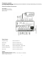
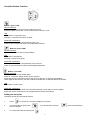
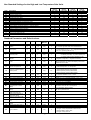
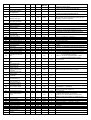
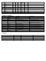
Solo Plus units
with Power
Split Controller
Contents
Contents
Temperature controller
Printed Circuit Board Connections
Relay Outputs
Probes
Controller Button Function
Setting the Set Point
Accessing the Parameters
Modification of the type ‘F’ (frequent) parameters
Modification of the type ’C’ parameters
Non standard settings for the High and Low temperature Solo Units
Standard Parameters and default Values
Alarms and Warnings
Parts List
1
Page
2
2
2
2
3
3
4
4
4
5
5 to 7
7
7
Temperature controller
It is strongly advised that before adjusting any Service Parameters a thorough understanding of the following
instructions should be obtained.
Printed Circuit Board Connections.
Power Supply:
Live: 250Vac max. 30A max.
Neutral: 250Vac max. 30A max.
Earth: 30A max.
Relay Outputs.
Compressor relay:
250Vac16A 2HP max
Defrost relay:
250Vac 16A resistive max.
Fan relay:
250Vac 10A resistive (2A) max.
Auxiliary 1/ Light relay:
250Vac resistive 500W – 1000VA max.
Auxiliary 2/ Demist relay.
250Vac 10A resistive (2A) max.
Alarm relay:
250Vac 10A resistive (2A) max.
Probes.
Standard Carel NTC 10K 25C - +/- 1°C
Range of measurement: -50T90 (-50 +90°C. –58 +195°F) 0.1°C resolution
Maximum length of 30metres.
2
Controller Button Function.
1
3
2
Button 1 (green LED)
Normal Operation
Pressed for 1 second to switch interior light ON or OFF.
Pressed together with button 2 for 5 seconds starts continuos cycle.
LED.
On Constant = Compressor ON.
Flashing = Compressor activation request.
Parameter modification.
Press once to move from one parameter to the next.
Press once to increase the value of the displayed parameter.
Button 2 (yellow LED)
Normal Operation
Press for 5 seconds to start a manual defrost.
LED.
On constant = Defrost ON.
Flashing = Defrost in progress.
Parameter modification.
Press once to move from one parameter to the previous.
Press once to decrease the value of the displayed parameter.
Button 3 (red LED).
Normal Operation
Press once to silence the audible alarm.
Press for 1 second to display and/or set the set point.
Press and hold for 5 seconds to access the menu for the type ‘F’ (frequent) parameters.
Press together with button 2, with the controller switched ON, to reset the default parameters.
LED
On constant = Alarm active.
Parameter modification.
Press once to display the value of the selected parameter, press again to exit the display.
Press and hold for 5 seconds to exit the parameters and save the changes.
Setting the set point.
To display the set point proceed as follows:
1.
Press
for more than 1 second to display the set point.
2.
To increase the set point press
value is reached.
3.
To confirm and save the value press
or to decrease the set point
3
press until the desired
Accessing the parameters
Modification of the type ‘F’ (frequent) parameters
Press and hold
for 5 seconds to access the menu.
Scroll through the parameters using the
On reaching the desired parameter press
To increase the value press,
or
buttons until the desired parameters is reached.
to display the value.
to decrease press
until the new value is achieved.
To confirm the value press
To modify further parameters repeat the operation.
To save the changes made press and hold
for 5 seconds.
Modification of the type ‘C’ parameters.
Press and hold
Press
for 5 seconds to access the menu.
once, 00 will be displayed.
Press and hold
until 22 (passcode) is displayed.
Confirm by pressing,
to 7.
the code or the first modifiable parameter will be displayed. See Parameter list on pages 5
Scroll through the parameters using the
or
On reaching the desired parameter press
to display the value.
To increase the value
buttons until the desired parameters is reached.
press, to decrease
press until the new value is achieved.
To confirm the value press
To modify further parameters repeat the operation.
Once all of the changes have been completed press
for 5 seconds to save the changes made, failure to carry out
this procedure will result in the changes made not being saved.
4
Non Standard Settings for the High and Low Temperature Solo Units
Code
/t
A0
A4
A5
Ad
AH
AL
c1
c2
c4
d0
dl
dp
dt
Lo
r1
r2
Electric
Defrost
High Temp
1
2
1
4
199
3
3
3
2
8
0
4
30
8
1
-5
10
Description
Terminal probe
Alarm and fan differential
Configure digital input 1
Configure digital input 2
Temperature alarm delay
High temperature alarm (delta)
Low temperature alarm (delta)
Minimum time between 2 compressor starts
Minimum compressor OFF time
Safety function Duty setting
Type of defrost. 0= Electric defrost. 1= Hot gas defrost
Interval between defrosts
Maximum/ effective defrost duration
End defrost temperature
Enable local ON/OFF
Minimum set allowed to user
Maximum set allowed to user
Electric
Defrost
Low Temp
1
2
1
4
199
3
3
3
2
8
0
4
30
8
1
-25
-15
Hot Gas
Defrost
High Temp
1
2
1
4
199
3
3
3
2
8
1
4
20
15
1
-5
10
Hot Gas
Defrost
Low Temp
1
2
1
4
199
3
3
3
2
8
1
4
20
15
1
-25
-15
Standard Parameters and Default values.
Code
PS
/2
Description
Password
Overall measurement
stability
Unit of
Measure
Type
Min
Max
F
0
199
Default
C
1
15
flag
4
22
/4
Virtual probe
C
0
100
%
0
/7
Display probe
C
0
4
flag
0
/t
Terminal probe
C
0
4
flag
4
/5
Centigrade/Fahrenheit
selector
C
0
1
flag
0
/6
Scale
C
0
1
flag
0
/8
Calibration probe 3
C
-19.9
19.9
°C/°F
0
/9
Defrost with probe S3
C
0
1
flag
0
/A
Presence of defrost probe/
product probe
C
0
3
flag
0.2
C
-19.9
19.9
°C/°F
0
C
C
C
C
C
C
-19.9
0
0
0
0
0
19.9
19.9
9
9
199
199
°C/°F
°C/°F
flag
flag
mins
mins
0
2
0
0
0
120
F
0
199
°C/°F
0
F
0
199
°C/F°
0
C
0
15
mins
0
C
0
15
mins
0
C
0
15
mins
0
C
0
15
mins
0
C
0
100
mins
0
C
c
0
0
15
15
hours
hours
2
4
C
0
3
flag
0
/C
/d
A0
A4
A5
A7
Ad
AH
Ambient probe calibration
S1
Defrost probe calibration
Alarm and fan differential
Configure digital input 1
Configure digital input 2
Delayed alarm input delay
Temperature alarm delay
High temperature alarm
(delta)
c6
cc
Low temperature alarm
(delta)
Compressor fan start
delay instrument ON
Minimum time between 2
compressor starts
Minimum compressor OFF
time
Minimum compressor ON
time
Safety function Duty
setting
Alarm bypass time after cc
Continuous cycle
d0
Type of defrost
AL
c0
c1
c2
c3
c4
5
Notes
Password for access to type C parameters (value 22)
1= medium low filter value, fast measurement
15= medium high filter value, slow measurement
Virtual probe on control probe and product probe
0= control probe S1 only, 1…99 = weighted average S1
– S3. 100 = product probe S3 only
Display: settings as for the terminal (/ t)
Terminal: 0= Not present: 1= ambient probe (S1)
2= defrost probe (S2): 3= product probe (S3)
4= control probe (virtual) (weighted S1 S3)
0= degrees Centigrade, 1= degrees Fahrenheit
0= display to the tenth, 1= display to the degree
NB this parameter only affects the display, and not the
Modification of the data.
0.1 resolution between –19.9 + 19.9°C
0= with defrost probe
nd
1= with defrost probe + 2 evaporator
0= defrost absent product probe absent
1= defrost absent product probe present
2= defrost present product probe absent
3= defrost present product probe present
0.1 resolution between –19.9 + 19.9°C
0.1 resolution between –19.9 + 19.9°C
Default 0.2°C, 0.1 resolution between –19.9 + 19.9
See non standard settings
See non standard settings
If A4 or A5= 2: 0= immediate
0= immediate
NB Deviation from the Set Point (normal or night time)
The alarms also shift as a consequence.
0.1°C resolution, always positive
NB: As for parameter AH
O= always OFF: 1…99= min: 100= always ON
0= electric defrost: end by temperature and/or time out
1= hot gas: end by temperature and/or time out
2= electric heaters: end by time
3= hot gas: end by time out
Code
Description
Type
Min
Max
Unit of
Measure
Default
Notes
0= start only, generic slave:
1= start + stop via network, PowerSplit slave
0= no. 1= yes
d2
Type of defrost control
C
0
1
flag
0
d4
Defrost at power up
Defrost delay at ON or
from digital input
C
0
1
flag
0
C
0
199
mins
0
d6
Display during defrost
C
0
1
flag
1
d8
Alarm bypass time after
defrost or door open
F
0
15
hours
1
C
0
1
flag
0
0= no. 1= yes
F
F
0
0
15
199
mins
hours
2
8
0= disabled
F
1
199
mins
30
Effective if d0= 2 or 3 or LAN defrost
F
-50.0
199
°C/°F
4.0
0.1°C resolution
0= always on, exept specific phases F2, F3, Fd
1= temperature control with evaporator temperature
0.1°C temperature resolution, valid if F0= 1
d5
0= display temperature alternating with ‘dF’
1= display OFF, displays last temperature read
Relates to configuration of digital inputs
NB: If the delay is set to zero and the door is left open
indefinitely, no alarm is signalled
dt
Defrost priority over
Compressor protection
Dripping time after defrost
Interval between defrosts
Maximum/ effective
defrost duration
End defrost temperature
F0
Fan management
C
0
1
flag
0
F1
Fan ON temperature
Fans OFF with
compressor OFF
Fans OFF in defrost
Fans OFF in post dripping
Serial Address
AUX 1 function relay no. 4
AUX 2 function relay no. 5
Disable keypad
Unit Master/ Slave
configuration
Photocell sensitivity
Light on time from sensor
Enable local ON/OFF
Enable network ON/OFF
F
-40.0
50.0
°C/°F
5.0
C
0
1
flag
1
0= no: 1= yes only when F0= 0
C
F
C
C
C
C
0
0
1
0
0
0
1
15
199
7
7
1
flag
mins
1
1
1
5
6
0
0= no: 1= yes when F0 = 0 and F0 = 1
C
0
1
Flag
0
C
C
C
C
0
1
0
0
2
15
1
1
flag
mins
flag
flag
0
10
0
0
C
0
1
flag
0
C
-50.0
r2
°C/°F
-50.0
0.1°C resolution
C
r1
19.99
°C/°F
90.0
0.1°C resolution
C
0
1
flag
0
C
-20
20
°C/°F
3.0
C
0
1
flag
0
0= no. 1= yes
Note: switching OFF/ON resets the reading
C
0
1
flag
0
0= disabled. 1= enabled
F
0
19.9
°C/°F
2.0
F
0
0
°C/°F
0
0.1°C resolution
F
0
0
°C/°F
0
0.1°C resolution
F
0
0
hours
0
C
0
1
flag
1
d9
dd
dl
dp
F2
F3
Fd
H0
H1
H2
H3
In
L1
Lt
Lo
LL
Ld
r1
r2
r3
r4
r5
r6
rd
rH
rL
rt
S8
Propagation of DIN 2 on
LAN
Minimum set allowed to
user
Maximum set allowed to
user
Signal enabling Ed
(defrost time-out)
Night time Set Point
Enable minimum
maximum temperature
monitoring
Night-time control with
product probe
Control differential
(hysteresis)
Maximum temperature
measured during ‘rt’
Minimum temperature
measured during ‘rt’
Effective temperature
measurement interval
RS485 serial
communication speed
Sn
Number of slaves
C
0
5
flag
1
St
Temperature Set Point
C
rt
r2
°C/F°
-10.0
to
Reset HACCP alarms –
HA-HF
C
0
1
flag
0
C
C
C
C
C
C
C
C
C
1
0
0
1
0
0
0
0
0
7
23
59
7
23
59
199
10
23
days
hours
mins
days
hours
mins
mins
hours
0
0
0
0
0
0
0
0
0
C
0
59
mins
0
*tu
*th
*t*
/tu
/th
/t*
tr
T1
-T1
_T1
Weekday HA event
Hours HA event
Minutes HA event
Weekdays HF event
Hours HF event
Minutes HF event
HACCP alarm delay
st
Defrost event No. 1 day
st
Defrost event No. 1 hours
st
Defrost event No. 1
minutes
…
6
0= master. 1…199= slave
Not used on Solo Units
Not used on Solo Units
0= enabled. 1= disabled
0= Slave
1= Master – for stand alone units leave the default (0)
0= disabled: 1= low sensitivity: 2= high sensitivity
1= local on/off enabled. 0= local on/off disabled.
1= network on/off enabled. 0=network on/off disabled.
If Master: 0= do not propagate status of DIN2
1= propagate status of DIN 2
If Salve: 0= do not usr propagated status of DIN2
1= use the propagated status of DIN 2
0.1°C resolution
0= 9600 Baud. 1= 19200 Baud.
Only on Master unit 0= no slave connected on Slave or
stand-alone unit leave Default (=1)
0.1°C resolution
0= HACCP alarm not reset
1= HACCP alarm present, can be reset.
Variable only for HACCP alarms, and reset either
explicitly or from HACCP button on LARGE terminal.
Display only (range 1…7, Monday…Sunday)
Display only (range 1…7, Monday…Sunday)
0= disabled
Date day for defrost event (see Table 3)
Date hours for defrost event
Date minutes for defrost event
Code
Tn
-Tn
_Tn
…
T6
-T6
_T6
tM
th
td
Description
nd
Defrost event No. n day
nd
Defrost event No. n
hours
nd
Defrost event No. n
Minutes
nd
Defrost event No 6 day
nd
Defrost event No 6 hours
Defrost event No 6
minutes
Current minutes
Current hours
Current weekday
Unit of
Measure
Type
Min
Max
Default
C
0
10
C
0
23
hours
0
C
0
59
mins
0
C
0
10
C
0
23
hours
0
C
0
59
mins
0
C
C
C
0
0
1
59
23
7
mins
hours
days
0
0
0
0
0
Notes
Date day 0= disabled
Date day 0= disabled
nd
Alarms and Warnings
Alarm Code
E1
E2
E3
rE
IA
Id
dA
Buzzer/ Alarm relay
Not active
Not active
Not active
ACTIVE
ACTIVE
ACTIVE
ACTIVE
Description
Probe 1 error
Probe 2 error
Probe 3 error
Control probe error
Immediate external alarm
Duty setting from external contact
Delayed external alarm
EA
Not active
E2P / clock alarm
HI
LO
HA
HF
Ed
NX (X=1…5)
NX (X=1…5)
tC
/cn
E0
dF
ACTIVE
ACTIVE
ACTIVE
ACTIVE
Not active
ACTIVE
ACTIVE
Not active
Not active
….
….
Not active
High temperature alarm
Low temperature alarm
HACCP alarm, time exceeded
HACCP alarm power failure
Defrost ended by time out
Slave X alarm
Slave X not communicating
Reset clock
Door open for too long
No compressor with PSB
No compressor with PSB
defrost
Models featured
ALL
ALL
ALL
ALL
ALL, if external alarm configured
ALL, if Duty setting configured
ALL, if delayed alarm configured
ALL
NB. In units without RTC for E2P only
ALL
ALL
Units with RTC configured as MASTER only
Units with RTC configured as Master only
ALL
Units with RTC configured as Master only
Units with RTC configured as Master only
Units with RTC only
ALL, if door input configured
ALL
ALL
ALL
Parts List
Item
Keyboard
PCB
RS485 Interface
Probes
Remote control Panel
Description
3TST015
3SCH082
3SCH083
3SNS058
2PRM770
Part Number
15344092
15344093
15344097
15344058
15344095
7
Model
SP LWPS
ALL
ALL
ALL
SP HCPS. SP LCPS
Foster European Operations
France
Foster Refrigerator France SA
Tel: (33) 01 34 30 22 22. Fax: (33) 01 30 37 68 74.
Email: [email protected]
Germany
Foster Refrigerator Gmbh,
Tel: (49) 2333 839375. Fax (49) 2333 839377.
Email: [email protected]
Foster Refrigerator
Oldmedow Road
Kings Lynn
Norfolk
PE30 4JU
Tel: 01553 691122
Fax: 01553 691447
Website: www.fosterrefrigerator.co.uk
Email: [email protected]
a Division of ‘ITW (UK) Ltd’
SPUNITS POWER SPLIT SM/01/05
8