1
TESTING THE THROTTLE POSITION SENSOR:
A properly adjusted and functioning throttle position sensor is essential to the proper operation of the NOS Mini Progressive
Controller. The TPS is a precision electrical component that acts as a variable resistor. The ECU provides a reference voltage
to the TPS. As the resistance varies with the throttle angle, the TPS provides a return signal to the ECU.
1.
Locate the vehicle’s TPS sensor, and the associated wires that attach to it.
2.
Connect the positive (+) lead of a digital voltmeter set to measure DC voltage to the TPS signal wire (there are 3 wires on
the TPS) leading to the TPS and the negative (-) lead of the voltmeter to a good chassis ground.
3.
Turn the ignition key to the “on” position.
4.
Using the positive lead of the voltmeter, probe the wires that connect to the TPS sensor. One wire will have a constant 5
volt signal to it (reference), the other wire will be a ground wire, and the remaining wire will be the signal wire.
5.
When the “signal” wire is located, note the voltage that is output with the throttle closed. This value will typically be 1 volt or
less, depending on the application.
6.
Slowly open the throttle and observe the voltmeter’s readout. The voltage should increase smoothly from the closed throttle
voltage to 4.0 to 5.0 volts at wide-open throttle.
7.
Remove the voltmeter wires from the TPS connector.
8.
Connect the provided connector onto the wire that has a 0 to 5 volt output.
NOTE: Some vehicles may have a “falling” voltage signal output. If this is the case, make sure you use setting 0 2
when setting the TPAS mode (See Configuration Step 8).
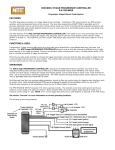
RUN MODE: This mode indicates the status of the Mini Controller
The LEDs (A.B.C.) will show the unit’s status:
r r
indicates the unit is ready, but untriggered
12
indicates the unit is triggered (1=ch1 & 2=ch2)
PP
indicates that the unit is in ramp pause mode and is currently paused
- indicates that the unit has timed out (30 seconds)
Switch 1 - resets the controller
Switch 2 - displays RPM
Switch #1
Switch #2
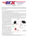
PROGRAMMING THE MINI PROGRESSIVE CONTROLLER:
Switch #1 - toggles through the configuration menu. As you toggle through the configuration menu, the stored value will be
displayed. Use this switch to toggle to the next step in programming mode (Press switch #1 2 times).
Switch #2 - increments the flashing value that was selected by switch #1.
LED A.B.C - displays the configuration step number and its setting
A = this is the step being programmed
B C = value for the current configuration step
A B C
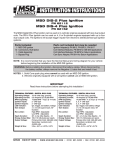
To enter the programming mode:
Press and hold both switches until “Pro” is displayed. Now release the switches and the unit will automatically go to the first
configuration step.
STEP F. SOLENOID FREQUENCY (Hz)
B C is the frequency that the solenoids are driven at (NOS recommends a default setting of 15 Hz
for our solenoids).
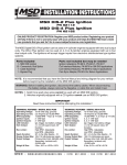
STEP C. RPM SIGNAL SET-UP – (This mode sets up the controller to work with the style of ignition system that your
vehicle uses. A brief description of each setting and its application is included after each option).
B C is the number of cylinders. This setting is used by the RPM WS to calculate the correct RPM.
0 0 = individual coil per cylinder systems where the ground trigger wire is connected to the coil.
Connect wire to the ground trigger on coil. (ex: the GM LS1 engine, 4.6 liter Ford Mustang, or
the Vortec 5.3 liter)
0 1 = coil packs that fire in pairs [waste spark systems]. Connect to ground trigger on coil. (ex: the Mitsubishi
Eclipse Turbo, Buick Grand National, or a wastespark/ dual outlet coil pack)
2