1
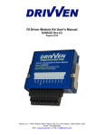
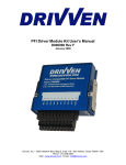
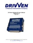
Spark Driver Module Kit User’s Manual
D000012 Rev F
January 2009
Drivven ,Inc. • 12001 Network Blvd.,Bldg.E, Suite 110 • San Antonio, Texas 78249 • USA
Phone : 210.248.9308
Web : www.drivven.com , E-mail : [email protected]
Drivven, Inc.
Spark Driver Module Kit
Contents Introduction ......................................................................................................................... 3
Pinout .................................................................................................................................. 4
Hardware ............................................................................................................................. 4
Powering the Module .......................................................................................................... 5
Platform Compatibility ....................................................................................................... 6
Spark Drivers ...................................................................................................................... 7
Software Installer .............................................................................................................. 12
Creating a LabVIEW Project ............................................................................................ 14
Sub VI Documentation ..................................................................................................... 20
Spark Command Scheduling Notes .................................................................................. 23
Warning About FPGA I/O Node Wiring .......................................................................... 24
© Drivven, Inc. 2009 • Spark Driver Module Kit User’s Manual • D000012 • Rev F
2
Drivven, Inc.
Spark Driver Module Kit
Introduction
The Spark Driver Module Kit provides a CompactRIO (cRIO) module for driving up to eight
ignition coils. The kit includes LabVIEW FPGA VIs for controlling all driver channels, individually
controlled for timing.
Features:
¾
8-channel inductive-type ignition coil driver
o Software configurable for dual output coils (wasted spark)
o 7A primary peak current maximum per pulse
o Short circuit protection
o Internally fuse protected at 10A
o Module over-temperature protection
¾ External power supply of 6-32V
© Drivven, Inc. 2009 • Spark Driver Module Kit User’s Manual • D000012 • Rev F
3
Drivven, Inc.
Spark Driver Module Kit
Pinout
Hardware
The Spark Driver Module Kit provides eight inductive-type ignition coil drivers in a National
Instruments CompactRIO module.
Revision Notes:
Revision F of the Spark Driver Module Kit incorporates firmware and software changes that are
not compatible with previous versions of the module. Software for revision F will not recognize
modules of previous versions. Be sure to use the RevF FPGA VIs with the RevF module.
© Drivven, Inc. 2009 • Spark Driver Module Kit User’s Manual • D000012 • Rev F
4
Drivven, Inc.
Spark Driver Module Kit
Powering the Module
The Spark Driver module requires power from two different sources.
One source is from the CompactRIO backplane male high density D-Sub 15-pin (HD15)
connector which mates with the module’s female HD15 connector. This power source provides a
regulated 5 volts and ground to various digital logic functions within the module. The
CompactRIO 5V source is active whenever the CompactRIO or R-Series Expansion Chassis is
properly powered. The module should only be powered at the HD15 connector by plugging it into
a CompactRIO or R-Series Expansion Chassis. The module’s HD15 connector should not be
connected to any other device.
Another required power connection is at the external screw terminal connector. The terminals are
labeled BATT (0) and GND (9). Typical power sources will be from automotive 12V or 24V
battery systems. However, the module can accept power from a range of 6V to 32V. With no
actuators connected, the module requires up to 100mA from the external supply. However, the
external supply must be capable of powering the actuators connected to the module. Therefore a
battery or power supply capable of 7A may be necessary under full load.
The external battery power ground is completely isolated, within the module, from the
CompactRIO 5V supply ground. However, the external battery ground and the CompactRIO
ground may be connected externally.
The module will not be recognized by software without both power supplies active.
Warning: The external battery supply input terminals are not reverse voltage polarity
protected. Connecting power to the module in reverse polarity will damage the module.
This event is not covered by the warranty. Please refer to the
DrivvenReverseBatteryNotice.pdf document (available on the website) for a recommended
solution for protecting a system from reverse battery polarity.
© Drivven, Inc. 2009 • Spark Driver Module Kit User’s Manual • D000012 • Rev F
5
Drivven, Inc.
Spark Driver Module Kit
Platform Compatibility
CompactRIO modules from Drivven are compatible within two different platforms from National
Instruments. One platform is CompactRIO, consisting of a CompactRIO controller and
CompactRIO chassis as shown in Figure 1a below.
Figure 1a. CompactRIO platform compatible with Drivven CompactRIO modules.
The other platform is National Instruments PXI which consists of any National Instruments PXI
chassis along with a PXI RT controller and PXI-78xxR R-Series FPGA card. An R-Series
expansion chassis must be connected to the PXI FPGA card via a SHC68-68-RDIO cable. The
CompactRIO modules insert into the R-Series expansion chassis. This platform is shown in
Figure 1b below.
Figure 1b. PXI platform compatible with Drivven CompactRIO modules.
Drivven CompactRIO modules are not compatible with the National Instruments CompactDAQ
chassis.
Drivven CompactRIO modules REQUIRE one of the hardware support systems described above
in order to function. The modules may not be used by themselves and/or interfaced to third party
devices at the backplane HD15 connector. These efforts will not be supported by Drivven or
National Instruments.
© Drivven, Inc. 2009 • Spark Driver Module Kit User’s Manual • D000012 • Rev F
6
Drivven, Inc.
Spark Driver Module Kit
Spark Drivers
Each spark driver channel is capable of directly driving a single ignition coil primary and is
independently controlled for timing and dwell. Each channel is capable of driving to a peak of 7
amps. During operation, a channel is turned on (low-side switch to ground), sinking current
through the primary winding of an ignition coil, thus storing magnetic energy in the coil. When the
channel is switched off, the magnetic field of the primary quickly collapses causing the voltage
across the secondary winding to spike, delivering a spark across the gap of a connected spark
plug. The spark must find a path to battery ground via ground connection with the spark plug
body. The engine cylinder head will provide a ground path for the threaded spark plug body and
must have a ground connection back to battery.
The Spark Driver Module Kit is not intended to control “smart” ignition coils with built-in driver or
igniter circuits. Smart coils require digital commands, whereas the Drivven Spark Driver Module
contains low-side switches for sinking current through a standard ignition coil primary winding.
For commanding smart coils, consider the Drivven Engine-Synchronous TTL Output Module Kit.
The amount of time that the driver channel is turned on, or dwell time, will, in part, determine the
voltage that can be achieved at the spark plug gap. The gap length also determines the spark
voltage. The dwell time required to achieve certain spark energy will vary with the characteristics
of the ignition coil. For example, the dwell time required to achieve 20 kvolts at the spark gap
using different coils could range from a few hundred microseconds to four milliseconds. The
voltage actually required for combustion will also depend on other engine parameters. This spark
driver module is intended to be used to drive a wide variety of ignition coils, but the user must
understand the proper range of dwell times for the coil used or damage to the coil and driver
could occur. It should also be understood that longer dwell time does not necessarily correlate to
better combustion. The dwell time only needs to be long enough to achieve a reliable spark
under the engine operating conditions and battery voltage. More dwell time, in excess of what is
needed to achieve reliable spark, wastes energy and needlessly heats the driver module.
Determining Dwell Time
The best way to determine required dwell time for a specific coil application is to measure the
dwell of the coil within an OEM installation. While performing measurements, be sure to measure
the dwell of at least three different battery voltages, if possible, in order to build a table of dwell
times versus battery voltage. If a datasheet is available for the coil, a table of dwell versus
battery voltage may be provided in order to achieve a certain peak current in the primary.
It is possible to safely determine the required dwell time for a given ignition coil by performing a
simple bench test. The test will require a variable-voltage power supply capable of 7 peak amps,
an oscilloscope, a current probe and a spark tester device.
Using the built-in simulator feature of the Engine Position Tracking VI, the user can simulate a
running engine and generate sparks on a test bench by connecting a test coil to a spark driver
channel and a spark tester device to the coil. A spark tester device is a low cost tool sold at most
auto parts stores which fits into the boot of a coil or plug lead just like an ordinary spark plug. The
gap of the tester is adjusted by a threaded rod with a pointed tip. The body of the spark tester is
marked for approximate gap voltages. The tester shown in Figure 2 is made by Thexton (part
#404) and is sold for approximately $10 USD. The spring clip must be connected to battery
ground to provide a ground path for the spark. If the spark does not have a ground path back to
battery, then there will not be a spark seen at the gap. Instead, the ignition coil will arc within
itself and could cause damage to the coil.
© Drivven, Inc. 2009 • Spark Driver Module Kit User’s Manual • D000012 • Rev F
7
Drivven, Inc.
Spark Driver Module Kit
Figure 2. Thexton adjustable spark tester. Part #404.
WARNING! Automotive ignition coils can generate lethal voltages! The user should be
extremely careful when handling the ignition coil, spark plug or spark testing device. Do
not touch the coil or spark tester device while performing spark tests. Do not attempt to
adjust the spark tester while performing spark tests. Remove power to the ignition circuit
before handling any of these parts. Receiving an automotive ignition spark at any voltage
can be very painful. Persons with medical devices or heart conditions should not be
involved with testing or installing ignition systems.
Use a current probe to monitor the current through the primary while conducting dwell tests. Most
passenger car ignition coils require 3-7 peak amps to achieve a consistent spark. If the coil
manufacturer’s recommended current rating is not known, then it is good to use the current probe
to know if excessive current is required to achieve spark. If more than 8 amps are required to
achieve spark then the module will not be able to drive the coil at higher engine speeds without
overheating. The module is fuse protected for a total current of 10 amps.
Prepare an application for simulating a running engine using your EPT VI. There is an example
application included with the Spark Driver Module Kit for this purpose.
The Spark Driver Module should be powered externally from the same power supply (battery)
voltage which feeds the high-side of the ignition coil(s). Connect one side of the coil primary to
battery voltage and be sure to use an automotive fuse (7.5A) in this connection. We are all
prone to making mistakes with connections and software settings! It is better to blow an external
fuse than the fuse within the module. Connect the other side (low side) of the coil primary to the
spark driver module channel that you will be using for test. Connect the coil secondary to the
spark tester device. This connection will vary with coil and test device. Be sure to connect the
other side of the spark tester device back to battery ground.
The user should adjust the spark tester for a spark voltage of 10-20 kvolts. Then starting with a
dwell time of approximately 0.1 msec, increase the dwell until spark is achieved. Use the current
probe to double check that current limits are not being exceeded as dwell is increased. For
example, if the tester device were not connected properly for some reason, the user would see
current increasing with dwell, but never see a spark, and appropriate measures could be taken to
discover the problem. The dwell required for a 10-20 kvolt spark is most likely sufficient for
achieving reliable combustion at moderate to high loads. Of course this requirement will vary with
many different factors, but this test will provide the user with a typical dwell time for the given
ignition coil. During engine operation, required dwell time will depend on battery voltage. As
battery voltage decreases, dwell time must increase to achieve the same spark energy. The user
© Drivven, Inc. 2009 • Spark Driver Module Kit User’s Manual • D000012 • Rev F
8
Drivven, Inc.
Spark Driver Module Kit
can perform a bench test with a variable power supply to determine how dwell time depends on
battery voltage. These values can be implemented in a lookup table in LabVIEW using Drivven’s
RT table lookup VIs or CalVIEW table lookup VIs. Do not use a fixed dwell time in your
application if you expect the battery voltage to vary. This could lead to weak sparks or blowing
the module fuse.
© Drivven, Inc. 2009 • Spark Driver Module Kit User’s Manual • D000012 • Rev F
9
Drivven, Inc.
Spark Driver Module Kit
Ignition coil primaries should be wired to the Spark Driver Module according to Figure 3. An
automotive 7.5A fuse is recommended to be used in series with the high sides of the primaries.
Battery or
Power Supply
(12V Typical
- @ >10A Peak) +
0
1
2
3
4
5
6
7
8
9
Automotive 7.5A fuse
Ign. Coil
S
P
+
Spark Plug
-
Spark Module Connector
Ign. Coil
S
P
+
Spark Plug
-
Figure 3. Connecting ignition coils to the driver module.
Notes:
1.) Use 18AWG or larger diameter wire.
2.) Spark plug body must have ground path back to battery.
3.) A CompactRIO controller may be powered by the same power source or by an isolated
power source. If the cRIO controller is powered by the same battery and this battery is
used for cranking the engine, then it is possible that the battery voltage will drop below
9V during cranking, causing the cRIO controller to reset. This can be prevented by using
a small backup battery and a diode pack for the cRIO controller. Please contact Drivven
for recommended parts and connections.
4.) When using wasted spark ignition coils which have two secondary connections per
primary, Drivven recommends connecting two spark driver channels to each shared
primary (in parallel). Then use the two spark channels as if driving two independent
ignition coils.
© Drivven, Inc. 2009 • Spark Driver Module Kit User’s Manual • D000012 • Rev F
10
Drivven, Inc.
Spark Driver Module Kit
Driver Channel Protections
The spark driver channels are short circuit protected. However, there is no short circuit fault
detection reported via software. If a short circuit is present, the driver channel will immediately
disable itself during the dwell command. Another driver attempt will be made at the next pulse.
The driver channels are software limited to 5 msec of dwell, however, this may be much too long
for a given ignition coil. Therefore it is important that the user perform the above described bench
tests in order to fully understand the proper range of dwell time for a given ignition coil. Dwell
time should also be limited to approximately 25% duty cycle. For example, if an engine is running
at 8000 RPM, then the dwell time should be limited to 3.75msec. If wasted spark mode is
enabled or re-strike pulses are enabled, the dwell time must be limited even more. For example,
if an engine is running at 8000 RPM and wasted spark mode is enabled, then the dwell time
should be limited to 1.875 msec. If using double ended coils in wasted spark mode, and dwell
times are required to be greater than the maximum dwell calculated for wasted spark mode, then
two driver channels can be used to drive the same double-ended ignition coil, with wasted spark
mode disabled.
The spark driver module is internally protected from board temperature exceeding 85 degC.
When this temperature is exceeded, all driver activity will be shutdown until the temperature
drops to 55 degC. The over-temperature condition is reported by the SparkData cluster output of
the FPGA VIs.
© Drivven, Inc. 2009 • Spark Driver Module Kit User’s Manual • D000012 • Rev F
11
Drivven, Inc.
Spark Driver Module Kit
Software Installer
The Spark Driver Module Kit is provided with an installer package which may be downloaded
from Drivven’s Sharepoint website after obtaining login access from Drivven. User’s may go to
http://portal.drivven.com/SoftwareDownload and enter the provided username and password to
gain access to the specific product installer packages which have been purchased. The installer
packages are executables which should be run on the intended development computer, having
LabVIEW development tools installed. After installing the package, a “Start->Programs->Drivven>ProductRelease” menu item will be added to the desktop. The specific product will have an
example LabVIEW project appear under the “Examples” menu and the user manual will appear
under the “Manuals” menu. User’s may copy and open the example project to experiment with
the module or use as a starting point for a new application. All software files, example projects
and documentation are installed to:
C:\Program Files\National Instruments\LabVIEW X.X\vi.lib\addons\DrivvenProductRelease\.
When working with block diagrams, user’s will notice a “Drivven” function palette added to the
standard LabVIEW palette, specific for the RT or FPGA target. VIs for a specific Drivven product
will be categorized according to product name. Also, some Drivven products will install RT and
FPGA VIs under a “General” function palette which is intended to be used across multiple
products.
Requirements
The Drivven VIs require:
¾ LabVIEW 8.5 Full Development or later
¾ LabVIEW RT Module 8.5 or later
¾ LabVIEW FPGA Module 8.5 or later
¾ NI-RIO 2.4 or later
¾ Drivven EPT VI **
** The FPGA VI supplied with this kit cannot generate fuel commands without the supervision of an engine
position tracking (EPT) VI from Drivven. The EPT VI provides the necessary output cluster to be wired to
the FuelSparkSupervisor input cluster.
The Spark Driver Module Kit is provided with 14 different LabVIEW FPGA VIs. Each VI includes
an interface for controlling a different number of spark channels with non-multiplexed or
multiplexed internal spark control cores. This gives the user the ability to optimize FPGA
resources depending upon maximum engine speed and dwell requirements. There is also a
WasteSpark control input which allows the use of dual output ignition coils for pairs of opposing
cylinders.
Figure 4 shows the icon which represents all supplied VIs, having identical clustered terminals.
However, the contents of the SparkControl cluster will vary.
Figure 4. Spark VI icon with leads.
The FPGA VI must be placed within a Single Cycle Loop (SCL) of a LabVIEW FPGA block
diagram. The SCL must execute at the default clock rate of 40 MHz.
© Drivven, Inc. 2009 • Spark Driver Module Kit User’s Manual • D000012 • Rev F
12
Drivven, Inc.
Spark Driver Module Kit
The FPGA VI requires a pre-synthesized netlist file having a matching name and an extension of
.ngc. The netlist file must be located in the same directory as the matching VI. The installer will
place this file in the LabVIEW addons directory along with the FPGA VI.
© Drivven, Inc. 2009 • Spark Driver Module Kit User’s Manual • D000012 • Rev F
13
Drivven, Inc.
Spark Driver Module Kit
Creating a LabVIEW Project
Drivven recommends working from the provided example application as a starting point for
learning the use of the Drivven software blocks. However, the following section describes starting
a LabVIEW project from scratch and adding a Drivven module.
1.) Install the Drivven software by running the installer executable and accepting the
software license agreement.
2.) Restart LabVIEW, if previously running, and create a new LabVIEW project.
3.) Give the new project a name by clicking the “Save Project” button on the project toolbar.
4.) Right click on the highest item in the project hierarchy (“Project:…”) and navigate to
“New->Targets and Devices…”
5.) Within the “Add Targets and Devices…” dialog, select the appropriate radio button,
depending on whether you already have an existing powered and configured RT target
on the network or if you are adding a new RT target which is not present yet on the
network.
a. Existing Target or Device
i. Expand the appropriate category in the “Targets and Devices” list to see
the discovered targets in that category.
ii. Double-click the desired target to add it to your project.
b. New Target or Device
i. Expand the appropriate category in the “Targets and Devices” list to see
all possible targets within that category.
ii. Double-click the desired target to add it to your project.
6.) If the new RT target is not currently on the network, right-click on the RT target within the
project and open the properties dialog to set the IP address or DNS name if necessary.
7.) Right-click on the RT target within the project and navigate to “New->Targets and
Devices…”
8.) Within the “Add Targets and Devices…” dialog, select the appropriate radio button,
depending on whether you already have an existing FPGA target connected to an
existing RT target or if you are adding a new FPGA target which is not present yet.
a. Existing Target or Device
i. Expand the appropriate category in the “Targets and Devices” list to see
the discovered FPGA targets in that category.
ii. Double-click the desired target to add it to your project.
b. New Target or Device
i. Expand the appropriate category in the “Targets and Devices” list to see
all possible targets within that category
ii. Double-click the desired target to add it to your project.
9.) If the new FPGA target was not currently in the system, right-click on the FPGA target
within the project and open the properties dialog to set the resource name if necessary.
The resource name can be found from MAX when connected to the actual remote
system.
10.) If the FPGA target is a PXI or PCI card, then an R Series expansion chassis must be
added under the FPGA target. This is done by right-clicking on the FPGA target and
navigating to “New->R Series Expansion Chassis”. Within the following dialog, select the
appropriate FPGA connector to which the chassis will be connected. A unique name for
the chassis may also be specified.
11.) Right click on the R-Series expansion chassis or cRIO FPGA target chassis and navigate
to “New->C Series Modules…”
12.) Select the “New Target or Device” radio button and double-click on the “C Series Module”
in the “Targets and Devices” list. In the following dialog, select the desired Drivven
module at the bottom of the “Module Type” list. The Drivven modules will be appended
there if any Drivven module software has been installed. Select the appropriate module
© Drivven, Inc. 2009 • Spark Driver Module Kit User’s Manual • D000012 • Rev F
14
Drivven, Inc.
Spark Driver Module Kit
location. Finally, specify an appropriate name for the module, which will later appear in
the FPGA I/O nodes in the FPGA block diagram. Having meaningful module names is
important for preventing coding mistakes.
13.) After adding a module to the project, a folder will automatically be added to the project
having the same module name given in the module configuration dialog. The folder will
contain the FPGA I/O pins for the module slot. These I/O pins can be selected in the
block diagram when connecting the module VI PinInput and PinOutput clusters to FPGA
I/O nodes. The example application, discussed below, should be consulted for further
details about connecting the PinInput and PinOutput clusters to FPGA I/O nodes. Within
the example projects, notice the FPGA I/O node elements having module name prefixes.
14.) Some Drivven modules can be automatically recognized by LabVIEW when adding cRIO
modules to the project. However, Drivven does not recommend using this feature
because the module names, which are automatically assigned, are not meaningful
(Mod1, Mod2, etc) and can lead to coding mistakes when wiring the Drivven FPGA VIs to
the I/O nodes. Adding the modules to the project manually, as described above, is still
the recommended method.
© Drivven, Inc. 2009 • Spark Driver Module Kit User’s Manual • D000012 • Rev F
15
Drivven, Inc.
Spark Driver Module Kit
Brief Glossary of Terms
CAD: Crank Angle Degrees. There are 360 CAD per two stroke cycle or one crankshaft rotation.
There are 720 CAD per 4-stroke cycle, or two crankshaft rotations. In a 4-stroke engine, the
camshaft completes exactly one rotation per two rotations of the crankshaft. There are two
strokes of the piston (up and down) within the cylinder during a single rotation of the crankshaft.
A single stroke of the piston covers 180 CAD.
EXTRAP: Level of EPT Position Extrapolation. This is a fixed power of two by which the angular
resolution of tracked crankshaft position is improved over the physical teeth alone. For example,
if the EPT VI has a fixed extrapolation level of 7, then the crank angle resolution between each
physical tooth is improved by a factor of 2^7 = 128.
CAT: Crank Angle Ticks. Single unit of angular measure reported by the CurrentPosition output
of the EPT VI. Reported as a power-of-two angular ticks of crank position travel, having a
resolution dependent on EXTRAP and the number of physical teeth per crankshaft rotation. For
example, if using the N-M EPT VI, which has an extrapolation of 7, the number of CAT per crank
tooth would be 2^7=128, and CurrentPosition would be evenly incremented by 128 CAT from one
physical tooth to the next. If a 60-2 pattern were used, the maximum number of CAT per
crankshaft rotation (cycle) would be 60*128=7680. If the engine was a 4-stroke, the total number
of CAT per engine cycle would be 2*60*128=15360.
MAX_CAT: Maximum Crank Angle Ticks per engine cycle.
© Drivven, Inc. 2009 • Spark Driver Module Kit User’s Manual • D000012 • Rev F
16
Drivven, Inc.
Spark Driver Module Kit
Table 1 shows a list of all spark VIs included in this kit.
Table 1. Spark VI Configurations
VI Name
Spark
Cores
Used
Number of Spark Outputs
(WasteSpark = FALSE)
spark_vt_1mux1_revx.vi
1
1
spark_vt_1mux2_ revx.vi
1
2
spark_vt_2mux1_ revx.vi
2
2
spark_vt_1mux4_ revx.vi
1
4
spark_vt_2mux2_ revx.vi
2
4
spark_vt_4mux1_ revx.vi
4
4
spark_vt_1mux6_ revx.vi
1
6
spark_vt_2mux3_ revx.vi
2
6
spark_vt_3mux2_ revx.vi
3
6
spark_vt_6mux1_ revx.vi
6
6
spark_vt_1mux8_ revx.vi
1
8
spark_vt_2mux4_ revx.vi
2
8
spark_vt_4mux2_ revx.vi
4
8
spark_vt_8mux1_ revx.vi
8
8
As can be seen from Table 1, there are multiple VIs that support two, four, six and eight spark
driver outputs. For example, if an engine control system was being prototyped for an eight
cylinder engine with one coil per spark plug, then there are four different VIs to choose from
which support eight spark outputs. One of those VIs internally contains eight individual spark
cores, each controlling a single output. Another VI internally contains four spark cores, each
multiplexed to control two outputs. Another VI internally contains two spark cores, each
multiplexed to control four outputs. Finally, another VI contains a single spark core, multiplexed
to control all eight outputs. The VI chosen will depend upon the maximum dwell required for the
ignition coil and the maximum engine speed. The VI which has 8 spark cores will require more
FPGA resources than the VI which has a single spark core. If the non-multiplexing VI,
spark_vt_8mux1_revx.vi, is chosen, then it is possible for all spark outputs to overlap. If a
multiplexing VI is chosen, then consideration must be given to dwell and engine speed to ensure
that consecutive spark pulses generated by the same spark core will not interfere. The plots in
figures 5 - 8 show how the spark cores are multiplexed for each of the four eight-channel VIs.
© Drivven, Inc. 2009 • Spark Driver Module Kit User’s Manual • D000012 • Rev F
17
Drivven, Inc.
SparkCore1
Spark Driver Module Kit
1
2
SparkCore2
3
SparkCore3
SparkCore4
4
SparkCore5
5
6
SparkCore6
7
SparkCore7
8
SparkCore8
0
90
180
270
360
450
CAD
Pulse numbers note the spark output channel
540
630
Figure 5. spark_vt_8mux1_revx.vi contains 8 non-multiplexed spark cores.
SparkCore1
5
1
SparkCore2
6
2
7
3
SparkCore3
SparkCore4
8
4
0
90
180
270
360
450
CAD
Pulse numbers note the spark output channel
540
630
Figure 6. spark_vt_4mux2_revx.vi contains 4 spark cores multiplexed into 2 outputs each.
SparkCore1
3
1
0
6
4
2
SparkCore2
90
7
5
180
270
360
450
CAD
Pulse numbers note the spark output channel
8
540
630
Figure 7. spark_vt_2mux4_revx.vi contains 2 spark cores multiplexed into 4 outputs each.
SparkCore1
1
3
2
0
90
4
5
6
180
270
360
450
CAD
Pulse numbers note the spark output channel
7
540
8
630
Figure 8. spark_vt_1mux8_revx.vi contains 1 spark core multiplexed into 8 outputs.
© Drivven, Inc. 2009 • Spark Driver Module Kit User’s Manual • D000012 • Rev F
18
Drivven, Inc.
Spark Driver Module Kit
NOTE: The pulse output numbers shown in the plots above do not correspond to cylinder
numbers. There should be no attempt at cylinder number correlation to output channel
number. The reason is that spark channels must be configured with timing values in
sequential CAD order, NOT cylinder number order.
In order to determine which spark VI can be used, the following calculations should be performed:
Assume EPT Stroke = 4, MUX = 8 (1mux8), Maximum engine speed = 6000 RPM
MinDwellWindow (sec) = (60 * STROKE) / (2 * MUX * MaxEngineSpeed(RPM))
= (60 * 4) / (2 * 8 * 6000)
= 0.002500 sec
If MinDwellWindow is calculated to be less than the actual dwell required by the ignition coil, then
a VI should be selected with less multiplexing and the calculation should be performed again
using the corresponding MUX value. Do not forget to consider minimum battery voltage when
determining maximum dwell required by the coil.
© Drivven, Inc. 2009 • Spark Driver Module Kit User’s Manual • D000012 • Rev F
19
Drivven, Inc.
Spark Driver Module Kit
Sub VI Documentation
spark_vt_8mux1_revf.vi
This VI is for interfacing directly with the Drivven Spark Driver module and for providing a control
interface to the LabVIEW RT level.
Number of Spark Cores Implemented: (1, 2, 3, 4, or 8)
Number of Channels Operated:
(1, 2, 3, 4, 6, or 8)
The FPGA VI must be placed within a Single Cycle Loop (SCL) of a LabVIEW FPGA block
diagram. The SCL must execute at the default clock rate of 40 MHz.
The FPGA VI requires a pre-synthesized netlist file having a matching name and an extension of
.ngc. The netlist file must be located in the same directory as the matching VI. The installer will
place this file in the LabVIEW addons directory along with the FPGA VI.
The PinInput and PinOutput clusters are wired to LabVIEW FPGA I/O nodes which are configured
for a cRIO controller chassis or a cRIO R-Series expansion chassis. Refer to the LabVIEW
FPGA documentation for details about creating and configuring FPGA I/O nodes.
Connector Pane
Controls and Indicators
SparkControl This cluster contains controls for enabling and configuring the spark
channels.
SparkEnableX When TRUE, the spark command is enabled. When FALSE
(default), the spark command is disabled.
EndPositionX Spark pulses are generated with a trailing edge coinciding with
EndPosition. The length of the pulse will be according to Dwell. The leading
edge will be determined by the current requested Dwell and the current engine
speed. EndPosition will always take precedence over Dwell in the presence of
engine speed fluctuations. If the engine speed increases after the spark pulse
has started, then the actual dwell will be slightly shorter than the requested Dwell
to ensure that correct spark timing is achieved. Likewise, if the engine speed
decreases after the spark pulse has started, then the actual dwell be will slightly
longer than the requested Dwell. However, MinDwell will take precedence over
EndPosition to ensure that a spark occurs, even if it is late. Also, a maximum
dwell of 5 msec is enforced to protect the driver circuit, even if the end of the
spark pulse must occur before EndPosition. The units of EndPosition are CAT.
Drivven provides Offset2CAT.vi in the General RT VIs in the RT function palette.
This VI can be implemented at the LabVIEW RT level for converting spark
advance in CAD, with respect to a cylinder TDC, to CAT.
CutoffPositionX All spark pulse activity is "Cutoff" at CutoffPosition and reset for
the next pulse. For multiplexed VIs, CutoffPositon is the position at which the
next consecutive spark pulse parameters will be loaded for the given internal
spark core. For multiplexed VIs, CutoffPosition should be set to a position close
© Drivven, Inc. 2009 • Spark Driver Module Kit User’s Manual • D000012 • Rev F
20
Drivven, Inc.
Spark Driver Module Kit
to, but after the most retarded spark timing position. This is an approximate rule
and should be retarded out further if engine speed fluctuations are enough that
pulses are being cut short. For non-multiplexed VIs, CutoffPosition MUST
ALWAYS be at least 45 CAD after EndPosition. If the minimum spacing of 45
CAD is not maintained for non-multiplexed VIs, then spark commands will be
generated incorrectly. The units of CutoffPosition are CAT.
Drivven provides Offset2CAT.vi in the General RT VIs in the RT function palette.
This VI can be implemented at the LabVIEW RT level for converting
CutoffPosition in CAD, with respect to a cylinder TDC, to CAT.
Dwell Determines the length of the spark command delivered to the driver circuit.
Dwell is entered in terms of 40 MHz clock ticks and is internally limited to
200,000 ticks (5 msec). The value is also internally limited to 18 bits. Values
larger than 18 bits will roll over from zero.
Dwell(uint32 ticks) = Dwell(msec) * 40,000.
Drivven provides time2ticks.vi in the General RT VIs in the RT function palette.
This VI can be implemented at the LabVIEW RT level for converting time in
milliseconds to 40 MHz clock ticks.
OffTime Determines the length of inactivity following each spark pulse. It is
recommended to set this value to at least 100 usec. OffTime provides a
minimum amount of time for the command to be off to allow the actual spark to
occur before turning the coil back on. OffTime is entered in terms of 40 MHz
clock ticks and is internally limited to 16 bits. Values larger than 16 bits will roll
over from zero.
Dwell(uint32 ticks) = Dwell(msec) * 40,000.
Drivven provides time2ticks.vi in the General RT VIs in the RT function palette.
This VI can be implemented at the LabVIEW RT level for converting time in
milliseconds to 40 MHz clock ticks.
MinDwell Determines the minimum length of any spark pulse. It is possible that
dwell could be cut short of the requested Dwell due to engine speed fluctuations
or modifications to EndPosition. If MinDwell is not satisfied upon reaching
EndPosition, then the pulse will be extended until MinDwell. This will ensure that
a spark will always occur even if the timing is late. MinDwell should be set to a
minimum value of dwell that will still guarantee a spark. MinDwell is entered in
terms of 40 MHz clock ticks and is internally limited to 200,000 ticks (5 msec).
The value is also internally limited to 18 bits. Values larger than 18 bits will roll
over from zero.
The following equation applies for converting dwell times in milliseconds to 40
MHz clock ticks.
Dwell(uint32 ticks) = Dwell(msec) * 40,000.
Drivven provides time2ticks.vi in the General RT VIs in the RT function palette.
This VI can be implemented at the LabVIEW RT level for converting time in
milliseconds to 40 MHz clock ticks.
WasteSpark The WasteSpark input allows users to take advantage of dual
output coils that operate on a pair of 4-stroke cylinders that are 360 degrees out
of phase. While one cylinder is at top dead center compression, the pairing
© Drivven, Inc. 2009 • Spark Driver Module Kit User’s Manual • D000012 • Rev F
21
Drivven, Inc.
Spark Driver Module Kit
cylinder is at top dead center exhaust. A dual output coil will spark in both
cylinders at the same time, sparking into a combustible mixture in one cylinder,
while sparking into inert exhaust gases in the other. When WasteSpark is TRUE,
the number of available spark channels will be divided by 2. For example, in the
case of using an eight-channel spark VI, only the first four driver channels would
be used instead of all eight. Pulse 1 will be paired with pulse 5 on channel 1,
pulse 2 paired with pulse 6 on channel 2, pulse 3 paired with pulse 7 on channel
3, and pulse 4 paired with pulse 8 on channel 4. If using the waste spark mode,
and the dwell time per channel is greater than 25% duty, then WasteSpark
should be set to false and two spark channels should be used to drive the same
coil primary.
FuelSparkSupervisor This cluster input must be wired directly from the
FuelSparkSupervisor cluster output of a Drivven EPT VI. The FuelSparkSupervisor
cluster from a single EPT may be used to supervise any number of Drivven enginesynchronous output sub-VIs.
SparkPinInput These Boolean controls must be connected to their corresponding FPGA
I/O Node input item.
SparkPinOutput The Boolean indicator named IDSelectEn must be connected to a Set
Output Enable method of an FPGA I/O Method Node. The Boolean indicator named
IDSelectOut must be connected to a Set Output Data method of an FPGA I/O Method
Node. The remaining Boolean indicators must be connected to their corresponding
FPGA I/O Node output item.
SparkData Provides status indicators for the spark driver module.
ModulePresent Indicates that the module is present in the correct slot, externally
powered and recognized by Drivven software.
ModuleOverTemp Indicates that the module has exceeded its internal
temperature limit and temporarily shut down.
© Drivven, Inc. 2009 • Spark Driver Module Kit User’s Manual • D000012 • Rev F
22
Drivven, Inc.
Spark Driver Module Kit
Spark Command Scheduling Notes
The Spark VIs provide features that ensure the best possible spark command delivery, even
while the CPU makes modifications to EndPosition and Dwell asynchronously to engine position.
Modifications to Dwell (Dwell, MinDwell, OffTime):
1. Dwell parameters can be modified at any time.
2. If Dwell is modified during the main spark pulse to a value less than the previous
value of Dwell, then the pulse is continued until EndPosition.
3. If Dwell is modified to a value less than MinDwell (0, for example), then the pulse
will still be started according to the value of Dwell and engine speed, but MinDwell
will take precedence by sacrificing the requested EndPosition to ensure a spark
occurs. This scenario should be avoided. Spark pulses should be disabled with the
SparkEnable booleans.
4. If Dwell is modified during the main spark pulse to a value greater than the existing
dwell, then the pulse is continued only until EndPosition, unless CutoffPosition or
MAX_DWELL of 5 msec is encountered first.
Modifications to EndPosition:
EndPosition can be modified at any time. However, the value must not be advanced by more
than 45 CAD within a single engine cycle. This value is referred to as the History Window. The
spark VIs continually check the requested EndPosition with respect to the current crank position.
If the EndPosition is modified by the CPU to a position in the past, the spark VIs use the History
Window to determine whether a late spark pulse should be started.
1. For example, let's assume that a spark pulse is scheduled for an EndPosition of
200 Absolute CAD (ACAD) and a dwell time of 40,000 ticks (1.0 msec), such that
the spark pulse is scheduled to turn on at 150 ACAD. Let's also assume that the
CurrentPosition of the EPT VI is 140 ACAD when the CPU modifies EndPosition to
180 ACAD, which means that the required start of the pulse is now 130 ACAD.
This new start is in the recent past by 10 CAD. Since this is less than the 45 CAD
History Window, then the spark VI will immediately start the spark pulse even
though it is late. The dwell will be turned off at EndPosition as long as MinDwell is
satisfied.
2. As another example, let's assume that a spark pulse is scheduled for an
EndPosition of 200 ACAD and a dwell time of 40,000 clock ticks (1.0 msec) such
that the spark pulse is scheduled to turn on at 150 ACAD. Let's also assume that
the CurrentPosition of the EPT VI is 140 ACAD when the CPU modifies
EndPosition to 120 ACAD, which means that the required start of the pulse is now
70 ACAD. This new start is in the recent past by 70 CAD. Since this is greater
than the 45 CAD History Window, the spark VI will not generate a late pulse,
effectively skipping a cycle without a spark pulse. The following cycle will have a
pulse delivered starting at 120 ACAD.
CutoffPosition must be set so that the following conditions are satisfied:
1. In the case of non-multiplexed spark VIs, CutoffPosition must be set at least 45
CAD after EndPosition. If this minimum spacing is not maintained, then spark
commands will be generated incorrectly.
© Drivven, Inc. 2009 • Spark Driver Module Kit User’s Manual • D000012 • Rev F
23
Drivven, Inc.
Spark Driver Module Kit
Warning About FPGA I/O Node Wiring
Great care should be taken to ensure that I/O nodes are wired to the correct PinInput and
PinOutput clusters of the correct module VI. If wired incorrectly, then undefined behavior or
module damage could result. LabVIEW FPGA does not yet provide a method for 3rd party module
vendors to hide the DIO pins behind module VIs and still be portable to various system
configurations. Therefore, a double-check of the I/O node wiring is recommended.
Two LabVIEW FPGA code snippets are shown below from an ADCombo implementation which
illustrate this issue. Figure 9 shows the correct implementation of the FPGA I/O node block for
the PinOutput cluster of the ADCombo. On the other hand, figure 10 shows a coding mistake that
should be avoided. Notice the ADCombo output items where a Spark module output item is
selected instead of the correct ADCombo module output item. This means that the Spark (DIO5)
output is being driven by the ADCombo logic and will cause strange behavior of the spark
module, or possible damage.
Figure 9. Representative FPGA output node for ADCombo with correct output item selection.
Figure 10. Representative FPGA output node for ADCombo with incorrect output item selection
for DIO5. This will cause strange behavior or damage to the spark module. Applying meaningful
names to the modules within the project can help identify these coding mistakes.
© Drivven, Inc. 2009 • Spark Driver Module Kit User’s Manual • D000012 • Rev F
24