1
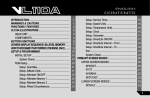
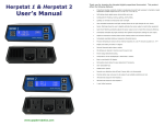
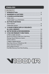
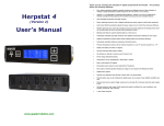
ENGLISH
CONTENTS
INTRODUCTION ................................................................
WARNINGS & CAUTIONS ................................................
FUNCTIONS / FEATURES ................................................
VL110HR ILLUSTRATIONS...............................................
HEAD UNIT...................................................................
COMPONENTS ............................................................
BUTTON FUNCTIONS.......................................................
SCREEN DISPLAY SEQUENCE: BI-LEVEL MEMORY ........
HOW TO RECOGNIZE YOUR TORPEDO (T2X MODEL ONLY) ..........
SETUP & PROGRAMMING ...............................................
INITIAL SETUP .............................................................
System Check ..........................................................
NOM SETUP.................................................................
Setup: Dual Bike ......................................................
Setup: Age ...............................................................
Setup: Maximum Heart Rate ...................................
Setup: Target Zone Upper Limit ...............................
Setup: Target Zone Lower Limit ...............................
Setup: Target Zone Audible Alarm ON/OFF .............
Setup: Wheel Circumference ...................................
1
1
Setup: Service Timer ...............................................
2
Setup: Speed Units ..................................................
3
Setup: Clock ............................................................
3
Setup: Odometer .....................................................
4
Setup: SmartLite ON/OFF .......................................
5
Setup: SmartLite Interval – From .............................
7
Setup: SmartLite Interval – To..................................
8
Exit ...........................................................................
10
System Check ..........................................................
10
10 PRIMARY SCREEN MODES .......................................................
UPPER SCREEN MODES ...........................................
11
SPD/DST .................................................................
12
RT/TT .......................................................................
12
AVG/MAX .................................................................
13
SPD*/CAD* ..............................................................
13
13
14
14
16
17
17
18
18
19
19
19
20
21
21
21
22
23
23
I
ENGLISH
CONTENTS
LOWER SCREEN MODES ..........................................
HR/% .......................................................................
CLK/ODO .................................................................
STP/IDS ...................................................................
SECONDARY SCREEN MODES......................................
AVG CAD*/ MAX CAD* ............................................
HEART RATE MEMORY STORAGE & RECALL.....
OTHER FEATURES ..........................................................
SLEEP MODE..........................................................
AUTO FIRE UP ........................................................
SMARTLITE .............................................................
DUAL BIKE MEMORY .............................................
SERVICE TIMER .....................................................
SPEED COMPARATOR ..........................................
AUDIBLE & VISUAL ALARMS .................................
LOW BATTERY WARNING .....................................
FREEZE FRAME MEMORY ....................................
24
24
25
26
27
27
28
30
30
30
31
31
31
32
32
32
34
RESET.......................................................................
RIDE DATA RESET ........................................
STOPWATCH & INTERMEDIATE DISTANCE RESET....
ALL CLEAR TOTAL RESET............................
TROUBLE SHOOTING .............................................
CYCLING ........................................................
HEART RATE .................................................
CARE & MAINTENANCE .........................................
TARGET ZONE & FITNESS TRAINING ...................
TECHNICAL SPECIFICATIONS ...............................
WARRANTY POLICY ...............................................
CUSTOMER SERVICE CENTERS ...........................
OPERATION
II
35
35
35
35
36
36
37
38
39
43
44
46
INTRODUCTION
ENG
Thank you for purchasing a Vetta VL110HR cycle computer and Heart Rate Transmitter. Please take time to familiarize yourself
with all the functions of the VL110HR model so you can take full advantage of its programs. And don’t forget to store this
manual in a safe place for future reference!
WARNINGS & CAUTIONS
●
Vetta recommends that this product be installed only by a qualified bicycle retailer. Failure to read these instructions and/or
improper installation of this device may void the warranty. If in doubt about any aspect of the installation or operation of this
product, consult your local bicycle retailer for clarification.
●
The Head Unit and Heart Rate Transmitter are splash proof and sealed to withstand wet weather conditions. Do not
deliberately place them in water.
●
Avoid leaving the Head Unit exposed to extremely hot or cold weather conditions.
●
Overexertion can cause serious injury, including heart attacks. Some individuals cannot safely elevate their heart rate to the
levels of typically used heart rate training zones. No one should begin an exercise program without first obtaining medical
clearance, especially if there is a personal or family history of heart disease, high blood pressure, or if you are over age 40,
have diabetes, high cholesterol, smoke cigarettes, are overweight or are taking certain medications. Stop exercising and
seek medical attention if you notice signs of overexertion or heart problems, such as pain or pressure in the left or mid-chest
area or left neck, shoulder or arm, light-headedness, cold sweat, unusual paleness or fainting. Also note that the signals
used by this monitor may interfere with a pacemaker or other implanted devices. Consult the manufacturer of the implant
device and/or your physician prior to using this monitor.
1
FUNCTIONS / FEATURES
ENG
HD WL T2X
●
Current / Average / Maximum Speed
● ● ●
Speed Comparator
● ● ●
Cumulative Odometer
● ● ●
Trip Distance
● ● ●
Intermediate Distance
● ● ●
Current Heart Rate
● ● ●
Average & Maximum Heart Rate
● ● ●
Percent of Maximum Heart Rate
● ● ●
EZ-Set Programmable Upper/Lower HR Limit
● ● ●
Time -in, Above & Below Target Zone ●
● ●
Average HR -in, Above & Below Target Zone
● ● ●
User Selected Audible & Visible Alarms
● ● ●
Wireless HR Transmission
● ● ●
Smart Signal
2
HD WL T2X
● ● ●
Stopwatch
● ● ●
Ride Time
● ● ●
Total Time
● ● ●
Service Timer
● ● ●
Dual Bike Memory
● ● ●
Freeze Frame Memory
● ● ●
Energy Saving Sleep Mode
● ● ●
Low Battery Warning (Head Unit)
● ● ●
Low Battery Warning LED Indicator (Torpedo)
●
Auto Fire Up - Auto Start up & Awake ●
● ●
NiteLite with SmartLite Function
● ● ●
Current / Average / Maximum Cadence
●
12/24 Hour Clock
VL110HR ILLUSTRATIONS
ENG
HEAD UNIT
A
D
B
C
E
F
H
G
A
C
E
G
B
D
F
H
3
COMPONENTS
ENG
C R2 03 2
CR 2450
L
I- I
For All Models
For VL110HR HD
J Wired Speed Sensor with
A Bladed Spoke Magnet (SPD Magnet)
B Spacer
Mounting Bracket
C Bracket Rubber Pad
K Wire Securing Tape
D Bracket Rubber Pad (Riser Handlebar)
E Wireless Transmitter Shim /Torpedo Shim
F Zip-Ties
G Head Unit Battery (CR2450, 3-Volt)
H Alternative HR Transmitter Battery Pack
(CR2032 battery & Rubber Shim)
I Heart Rate Transmitter (CR2050 battery included)
4
For VL110HR WL
L WL Wireless Speed Transmitter
M WL Wireless Speed Active Mount
N Wireless Transmitter Battery
(A23, 12-Volt)
O Wireless Transmitter Battery Cap
ON
B AT T E R Y
CR2032
BATTERY PAD
3V
For VL110HR T2X
P Integrated T2X Torpedo
Q Integrated T2X Active Mount
R Composite Cadence Magnet
(CAD Magnet)
S Torpedo Battery (CR123A, 3-Volt)
T Torpedo Battery Cap
BUTTON FUNCTIONS
ENG
SETUP MODE
Button
1
Button
2
Sets digits or units
Advances to the next item, screen or setting mode
Advances digits or toggles through units
Hold for fast advance
Resets RT to zero for Service Timer
Button
Button
1
Button
4
Button
3
2
Button
3
Has no function in Initial Setup
Button
4
Turn on the NiteLite for 3 seconds
OPERATING MODE
Button
1
Scrolls through Lower Screen Modes
Scrolls through Freeze Frame display screens
Hold 2 seconds in HR/% screen Mode to display HR data from
Heart Rate Memory Storage and Recall
Hold 2 seconds in SPD/CAD* Mode to display Average and
Maximum Cadence ( *T2X model only)
Button
2
Scrolls through Upper Screen Modes
Press and hold 2 seconds in any Primary Screen Mode to
activate Freeze Frame memory.
5
OPERATING MODE
ENG
Button
3
Starts/stops RT/TT timers and Stopwatch
Reset RT/TT timers and other ride data to zero
Exits NOM Setup and advances to NOM System Check and
SPD/DST Mode
Button
4
Button
1
&
Turn on the NiteLite for 3 seconds
(simultaneously for 2 seconds with RT/TT Timers are off) :
Hold both in the SPD/DST Mode to enter NOM Setup
Hold both in the HR/% Mode to enter NOM Setup for heart
rate functions.
2
Button
Button
1
Button
4
Button
3
2
For T2X model only
Button 2 & 4 (simultaneously for 2 seconds with RT/TT Timers are off) :
Hold both in the SPD/DST Mode to enter ID Learning Setup Mode
6
SCREEN DISPLAY SEQUENCE: BI-LEVEL MEMORY
M
ENG
N
L
A
B
K
C
D
J
E
I
H
Upper Display
Lower Display
C Audible Alarm Icon
D Lower Screen Mode
G F
A
E
B
F
G
H
I
Bicycle Icon
Upper and Lower Target Zone Symbols
Sub-Display Average HR Symbol
Heart Rate/Speed Sbu-Display
Sub-Display Speed Symbol
J
K
L
M
N
Heart Rate Display
Stopwatch Icon
Service Timer/ Low Battery Icon
Speed Comparator Symbol
Upper Screen Mode
Remark: ( * ) Available until Upgrade to T2X model
7
HOW TO RECOGNIZE YOUR INTEGRATED T2X TORPEDO (T2X MODEL ONLY)
ENG
1. For VL110HR T2X or Upgrade to T2X models, your computer can ONLY recognize the Integrated T2X Torpedo after it goes
through the ID Learning procedure.
2. If your Integrated T2X Torpedo is purchased as a complete set with the VL110HR series computer, your computer has been
programmed to recognize the Torpedo in the factory.
3. If a new Integrated T2X Torpedo or Integrated T2X Active Mount is purchased for replacement, please follow the ID Learning
Procedure.
4. If a complete set of Integrated T2X Mounting Kit is purchased for your 2nd bike, please make sure you had chosen Bike II in
the NOM Setup Mode (see page 12, Section of Dual Bike Setup in NOM Setup), and follow the ID Learning Procedure.
8
ID LEARNING PROCEDURE
ENG
Step 1: Install the computer on the Integrated T2X Active Mount.
Step 2: After the screen display “id NEEd”, press & hold the Torpedo’s button for 3 seconds. The
Light Ring Indicator of the Torpedo will turn on for 2 seconds in red.
Step 3: During the process, the computer will display “id LEArn” for 3 seconds.
Step 4: When done successfully, the computer will display “id donE” and gives 2 short beeps. The
computer will go back to the screen last displayed.
FAILURE
If the computer always displays “id NEEd”, please check if there are any objects emitting
electromagnetic waves (television, radio control toys, etc.). Keep the unit away from any object that
may be causing interference. Then press & hold the Torpedo’ button for 3 seconds again, and follow
the Step 3 & 4 to finish the ID Learning Procedure.
If this cannot solve the problem, re-install the battery and start from the Step 1 (as above) again.
Important To re-activate the ID Learning Procedure, press & hold 2 &
seconds in the SPD/DST Mode with RT/TT timers are off.
4
simultaneously for 2
9
SETUP & PROGRAMMING
ENG
INITIAL SETUP
The computer will automatically enter the Initial Setup Mode after
1. New battery replacement, or
2. All Clear Total Reset
In the Initial Setup, riders can complete all settings for the computer, which include the Basic settings and the Heart Rate
related settings.
The sequence of Initial Setup will be
Dual Bike → Age → Maximum Heart Rate → Target Zone Upper Limit → Target Zone Lower Limit → Target Zone
Audible Alarm ON/OFF → Wheel Circumference → Service Timer → Speed Units → Clock → Odometer → SmartLite
ON/OFF → SmartLite Interval-From → SmartLite Interval-To
Important After completed the Initial Setup, riders can change any values or correct any errors by re-entering the NOM Setup
(see page 11, Section of NOM SETUP)
SYSTEM CHECK
● After
10
the last setting, the computer will automatically advance to System Check.
●
System Check displays all value and unit settings chosen during Setup in sequence.
●
Each screen in System Check appears for 5 seconds and blink.
NOM SETUP
After completed the Initial Setup, riders can change any values or correct any errors by re-entering the NOM Setup.
ENG
The NOM Setup procedure is as followed.
NOM Setup for Basic Settings
1. Make sure RT/TT timers are off (press 3 in the RT/TT Mode and will disappear)
2. Press 1 and 2 simultaneously for 2 seconds in the SPD/DST Mode.
3. Press 3 at any time to exit the NOM Setup and advance to System Check.
4. After the last setting, the computer will automatically advance to System Check.
5. Press 3 at any time, the computer will exit the System Check.
The sequence of Basic Settings will be
Dual Bike → Wheel Circumference → Service Timer → Speed Units → Clock → Odometer → SmartLite ON/OFF →
SmartLite Interval-From → SmartLite Interval-To
NOM Setup for HR Settings
1. Make sure RT/TT timers are off (press 3 in the RT/TT Mode and will disappear)
2. Press 1 and 2 simultaneously for 2 seconds in the HR/% Mode.
3. Press 3 at any time to exit the NOM Setup and advance to System Check.
4. After the last setting, the computer will automatically advance to System Check.
5. Press 3 at any time, the computer will exit the System Check.
The sequence of HR Settings will be
Age → Maximum Heart Rate → Target Zone Upper Limit → Target Zone Lower Limit → Target Zone Audible Alarm ON/OFF
11
SETUP: DUAL BIKE
ENG 1. Press
2. Press
2
1
to toggle between Bike 1 or Bike 2
to select and advance to the next Setup Mode.
SETUP: AGE
1. Enter your age, VL110HR will automatically set the correct Target Zone for you.
2. Press 2 and scroll to your age.
3. Press 1 to select and advance to the next Setup Mode.
12
SETUP: MAXIMUM HEART RATE
VL110 HR will automatically calculate an initial Maximum Heart Rate when your age enters.
1. Press
2. Press
3. Press
1
2
1
ENG
to accept the suggestion and advance to next Setup Mode, or
to scroll to the desired Maximum HR.
to accept and advance to next Setup Mode.
SETUP: TARGET ZONE UPPER LIMIT
VL110 HR will automatically calculate an initial TZ Upper Limit when your age enters.
1. Press
2. Press
3. Press
1
2
1
to accept the suggestion and advance to next Setup Mode, or
to scroll to the desired TZ Upper Limit.
to accept and advance to next Setup Mode.
SETUP: TARGET ZONE LOWER LIMIT
VL110 HR will automatically calculate an initial TZ Lower Limit when your age enters.
1. Press
2. Press
3. Press
1
2
1
to accept the suggestion and advance to next Setup Mode, or
to scroll to the desired TZ Lower Limit.
to accept and advance to next Setup Mode.
13
SETUP: TARGET ZONE AUDIBLE ALARM ON/OFF
ENG
1. Press
2. Press
2
1
to toggle between ON or OFF
to select and advance to next Setup Mode
Important The Audible Alarm will alert the users when their heart rate are
above or below the pre-set Target Zone during an exercise session.
SETUP: WHEEL CIRCUMFERENCE
1. When the far right digit begins to flash, press 2 to scroll to the desired number (see page15, Section of WHEEL SIZE
CALCULATION)
2. Press 1 to select this no. and advance to next digit
3. Repeat for each digit until the final digit
4. Press 1 and advance to the next Setup Mode
14
WHEEL SIZE CALCULATION
Find your tire size and record the corresponding circumference measurement from the following chart lists.
ENG
If your wheel size in not on the chart, or if you want a more precise calibration, wheel circumference may be calculated as
follows:
Step1: Measure the distance from the centre of the front wheel axle the ground in millimeters. (1 inch =25.4 mm)
Step2: Multiply this distance by 6.2832(2π) and enter the result as the wheel size setting into the computer.
OR… Mark the tire and a spot on the floor. Roll the wheel forward one complete revolution until the tire mark touches the
floor again and mark that spot. Measure the distance between the marks on the floor millimeters and enter the result into the
computer.
15
SETUP: SERVICE TIMER ( )
ENG Step 1: Service Timer Interval (in hour)
Service Timer will be disabled when Service Timer Interval is set to “0000”
1. When the lower far right digit begins to flash, press 2 to scroll to the desired number.
2. Press 1 to select this no. and advance to next digit.
3. Repeat for each digit until the final digit.
4. Press 1 and advance to the Accumulated RT Reset Mode. (see Step 2)
Important In the Initial Setup, the Accumulated RT Reset Mode doesn’t exist, press
Units Setup Mode.
Step 2: Accumulated Ride Time (in hour)
To stop the Service Timer icon from flashing, reset the Accumulated RT to
Zero.
When the upper digits begin to flash, press & hold 2 to reset Accumulated
RT to Zero.
OR press
Mode.
16
1
repeatedly to reserve the digits, and advance to the next Setup
1
will advance to the next Speed
SETUP: SPEED UNITS
1. Press
2. Press
2
1
to toggle between KM/hr or Mile/hr
to select and advance to the next Setup Mode.
ENG
SETUP: CLOCK
1.
2.
3.
4.
5.
6.
Press 2 to toggle between 12hr or 24hr format, PM icon will appear only in the 12hr format.
Press 1 to select and advance to “hh:mm” setup.
When the far right digits begin to flash, press 2 to scroll to the desired number.
Press 1 to select this no. and advance to next flashing digit
Repeat for each digit until the final digit
Press 1 and advance to the next Setup Mode.
17
SETUP: ODOMETER
ENG 1. When the far right digit begins to flash, press 2 to scroll to the desired number
2. Press 1 to select this no. and advance to next flashing digit
3. Repeat for each digit until the final digit
4. Press 1 and advance to the next Setup Mode.
SETUP: SMARTLITE ON/OFF
1. Press 2 to toggle between ON or OFF
2. Press 1 to select. If set to ON, the computer will advance to the next
Setup Mode.
3. If OFF, it will exit the Setup mode and advance to System Check.
18
SETUP: SMARTLITE INTERVAL – FROM
1. Press
2. Press
2
1
to scroll from 1:00 PM to 11:00 PM
to select and advance to the next Setup Mode.
ENG
SETUP: SMARTLITE INTERVAL – TO
1. Press
2. Press
2
1
to scroll from 1:00 AM to 11:00 AM
to select and exit the Setup Mode and advance to System Check
EXIT
Press
3
at any time during the NOM Setup, and exit to System Check
Important If no buttons are pressed for approximately 5 minutes during Setup, the computer will automatically enter Sleep
Mode and then return to the screen last displayed when reactivated.
19
SYSTEM CHECK
ENG
20
● After
the last setting, the computer will automatically advance to System Check.
●
System Check displays all value and unit settings chosen during Setup in sequence.
●
Each screen in System Check appears for 5 seconds and blink.
●
Press
3
at any time to exit System Check and advances to the SPD/DST Mode.
PRIMARY SCREEN MODES
ENG
IMPORTANT: For VL110HR T2X or Upgrade to T2X models, your computer can ONLY recognize the transmitter—
Torpedo after it goes through the ID Learning procedure (see page 8 , Section of HOW TO RECOGNIZE YOUR
INTEGRATED T2X TORPEDO)
UPPER SCREEN MODES
UPPER/ LOWER DISPLAYS
SPD
DST
DEFINITIONS
CURRENT SPEED (km/hr or mile/hr)
CURRENT TRIP DISTANCE (km or mile)
HOW TO OPERATE?
● Starts automatically when the wheels turn and TT timer is running (see page 22, Section of RT/TT
Mode).
● Stops automatically when the wheels stop.
HOW TO RESET TRIP DISTANCE TO ZERO?
Press 3 for 2 seconds in any Primary Screen Mode except STP/IDS, with the RT/TT timers
turned off.
●
Important DST will automatically reset after the maximum trip distance (999.9) is achieved.
21
UPPER/ LOWER DISPLAYS
ENG
RT
TT
DEFINITIONS
ACTUAL RIDE TIME IN THE TRIP
TOTAL ELAPSED TRIP TIME
FORM START TO FINISH
HOW TO START THE TIMERS?
If the timers have been reset to “0:00:00”, they will start automatically when the wheel rotates. (see
HOW TO RESET THE TIMERS TO “0:00:00” below)
● If RT/TT timers had been stopped manually, and both of the RT/TT timers were not reset to zero,
they must be restarted manually by pressing 3 in RT/TT Mode.
●
Important TT timer must be active in order for the RT timer to accumulate Ride Time and for
computer to calculate current ride.
HOW TO STOP?
When the wheels stop, RT timer will pause, but TT timer will keep running to record the total
elapsed trip time.
● OR stop both of the RT/TT timers manually by pressing 3 in RT/TT screen Mode at the end of ride.
●
HOW TO RESET THE TIMERS TO “0:00:00”?
Press 3 for 2 seconds in Primary Screen Mode except STP/IDS, with the RT/TT timers turned off .
●
Tip:
If the bike is in motion and Button 3 is held down in the RT/TT Mode with the timers deactivated,
the ride timers reset to 0:00:00. When Button 3 is released, both RT and TT will start with the next
wheel input. This is a good way to begin timing a race or training ride with a rolling start.
22
UPPER/ LOWER DISPLAYS
AVG
MAX
DEFINITIONS
AVERAGE SPEED (km/hr or mile/hr)
MAXIMUM SPEED (km/hr or mile/hr)
ENG
HOW TO OPERATE?
● Starts automatically when the wheels turn and TT timer is running (see page 22, Section of RT/TT
Mode).
● Updated for every 0.1 miles or Km traveled.
● Stops automatically when the wheels stop.
HOW TO RESET TO ZERO?
Press Button 3 for 2 seconds in any Primary Screen Mode except STP/IDS, with the RT/TT
timers turned off.
●
UPPER/ LOWER DISPLAYS
SPD*
CAD*
DEFINITIONS
CURRENT SPEED (km/hr or mile/hr)
PEDAL CADENCE IN REVOLUTIONS
PER MINUTE (rpm)
*Available until Upgrade to T2X model
HOW TO OPERATE?
● Starts automatically when the wheels turn and TT timer is running (see page 22, Section of RT/TT
Mode).
● Stops automatically when the wheels stop.
23
ENG
SECONDARY MODE
1.Press & hold 1 to read Average & Maximum Cadence (see page 27, Section of AVG CAD/MAX
CAD Secondary Screen Mode)
2.Press 1 to exit.
LOWER SCREEN MODES
UPPER/ LOWER DISPLAYS
HR
%
DEFINITIONS
CURRENT HEART RATE (bpm)
PERCENTAGE OF USER DEFINED
MAXIMUM HEART RATE (bpm)
HOW TO OPERATE?
● Starts automatically when the computer receives Heart Rate signal.
● Stops automatically when no Heart Rate signal is received.
SECONDARY MODE
1. Press & hold 1 to read Heart Rate Summary. (see page 28, Section of HEART RATE SUMMARY
REVIEW)
2. Press 1 to exit.
Important 1. The heart icon will blink steadily when the Head Unit is receiving and recording a
Heart Rate signal from the transmitter. This icon disappears when no Heart Rate
signal is received.
2. Heart Rate reading displays in the lower left screen segment except HR/% Mode.
3. Current Speed is displayed in the lower left screen segment and “SPD” appears above
it in the HR/% Mode.
24
UPPER/ LOWER DISPLAYS
CLK
ODO
DEFINITIONS
CURRENT TIME
ODOMETER, CUMULATIVE
DISTANCE (km or mile)
ENG
HOW TO CHANGE THE CLOCK?
● See page 17, Section of CLOCK Setup.
HOW DOES THE ODOMETER WORK?
Automatically accumulate the trip distance when the wheels rotate and TT timer is running.
●
HOW TO RESET THE ODOMETER?
1. ALL CLEAR TOTAL RESET by press & hold 1 , 2 & 3 for 2 seconds in any mode, then release
the buttons.
2. OR new battery replacement
3. OR the ride distance exceeds the maximum limit, after which the Odometer will automatically reset
to zero.
Important Odometer reading can be re-installed by user.
25
UPPER/ LOWER DISPLAYS
ENG
STP
IDS
DEFINITIONS
INDEPENDENT STOPWATCH
OPERATES IN CONJUNCTION
WITH THE RT/TT TIMES
INTERMEDIATE DISTANCE TRACKS
AN INTERMEDIATE DISTANCE WITHIN
A LONGER RIDE (km or mile)
HOW TO START THE STOPWATCH?
Press 3 to start.
●
HOW TO STOP?
Press 3 to stop and freeze data for review.
●
HOW TO RESET THE STOPWATCH & INTERMEDIATE DISTANCE TO ZERO?
Press 3 for 2 seconds.
●
Important IDS does not affect overall Trip Distance or current ride data, but it operates the same
as the DST function.
26
SECONDARY SCREEN MODES
ENG
Important Flashing screen indicates the computer is displaying data in a Secondary Screen Mode.
UPPER/ LOWER DISPLAYS
AVG CAD*
MAX CAD*
DEFINITIONS
AVERAGE CADENCE (rpm)
MAXIMUM CADENCE (rpm)
*Available until Upgrade to T2X model
HOW TO ENTER THE AVG CAD/MAX CAD SECONDARY SCREEN MODE?
● Press & hold 1 from SPD/CAD Mode.
HOW TO EXIT?
Press 1 and exit to SPD/CAD Mode.
●
HOW TO RESET TO ZERO?
● Press 3 for 2 seconds in any Primary Screen Mode except STP/IDS, with the RT/TT timers
turned off.
27
HEART RATE SUMMARY REVIEW
ENG
1. At any point during a race or training ride, heart rate summary can be read in a 4 Screen sequence.
2. At the end of a ride or workout, the data will be frozen for reviewed, until reset to zero (see page 35, Section of RIDE DATA
RESET).
HOW TO READ THE HEART RATE SUMMARY?
● Press & hold 1 from the HR/% Mode.
SCREEN 1 (Time/ Upper Limit/ Avg HR ▲TZ)
● Upper Digits show the TIME you spend ABOVE the Target Zone
● Lower Digits show the Upper Limit of your Target Zone
● The Lower Left Hand Corner show your AVERAGE Heart Rate ABOVE
Target Zone
● Press 2 to Screen 2
1
2
SCREEN 2 (Time/ Avg HR In TZ)
● Upper Digits show the TIME you spend IN Target Zone
● Lower Display show the letters “IN”
● The Lower Left Hand Corner show your AVERAGE Heart Rate IN Target Zone
● Press 2 to Screen 3
2
28
SCREEN 3 (Time/ Lower Limit/ Avg HR ▼TZ)
● Upper Digits show the TIME you spend BELOW Target Zone
● Lower Digits show the Lower Limit of your Target Zone
● The Lower Left Hand Corner show your AVERAGE Heart Rate BELOW Target Zone
● Press 2 to Screen 4
SCREEN 4 (Avg/ Max HR)
Upper Digits show your AVERAGE Heart Rate for the whole ride
● Lower Digits show your MAXIMUM Heart Rate for the whole ride
● The Lower Left Hand Corner show Blank
● Press 2 back to Screen 1
ENG
2
●
HOW TO EXIT?
any time, press
● At
1
and return to the HR/% Mode.
2
HOW TO RESET TO ZERO?
● Press 3 for 2 seconds in any Primary Screen Mode except STP/IDS, with the RT/TT timers
turned off.
29
OTHER FEATURES
ENG
SLEEP MODE
●
●
●
To conserve battery life, the VL110HR computer is programmed to enter a Sleep Mode after
receiving no input from buttons, wheel motion, cadence* or heart rate for 5 minutes. (* T2X
model only)
The screen displays only the time of day.
All VL110HR bicycle computers will wake up by either of input signal from wheel/crank* motion or
any button is pressed. (* T2X model only)
AUTO FIRE UP
●
●
●
●
Auto Start up & Awake without wasting extra battery run time of the computers.
All VL110HR bicycle computers will exit Sleep Mode automatically when they receive inputs from the buttons or wheel/
crank* motion. (* T2X model only)
If the RT/TT timers read zero (0:00:00), the computer automatically starts as soon as it receives input from the wheels/
crank* motion. (* T2X model only)
If you did not stop the RT/TT timers manually before the computer enter the Sleep Mode, the RT timer will automatically
re-start as soon as it receives input from the wheels.
Important Any time the RT/TT timers are stopped manually and they are not reset to zero, they must be restarted manually
by pushing 3 in the RT/TT Mode.
30
SMARTLITE
SmartLite will activate the NiteLite for 3 seconds between the user-defined period when any button is pressed. (see page 18, ENG
Section of SmartLite Setup)
DUAL BIKE MEMORY( I II )
●
VL110HR can be calibrated for two bicycles. It will store separate Torpedo ID*, Wheel Size,
Service Timer, Odometer, as well as different formats selected for Time, Speed and Distance. (*
T2X model only)
● The current bike number (I or II) is always displayed in the lower right corner of the screen.
● To switch the computer quickly from Bike I to Bike II, go to the first screen in the NOM Setup Mode.
(see page 12, Section of Dual Bike Setup)
SERVICE TIMER (
)
● Service Timer
allows the rider to preset an exact number of riding hours during Setup
flashing Wrench icon when service time limit has been reached.
blinking Wrench icon indicates both low battery power in the Hea and expiration of the
preset service time interval.
● To stop the Wrench icon from flashing (see page 16, Section of Service Timer Setup)
● Slow,
● Rapid
31
SPEED COMPARATOR (▲▼)
ENG
●
The Speed Comparator symbols indicate whether current Speed is above or below Current
Average Speed.
● A positive (▲) or negative (▼) symbol appears in the upper left apart of the screen in all primary
screen modes.
● The Speed Comparator symbols do not appear if Current Speed and Average Speed are the
same.
AUDIBLE & VISUAL ALARMS (
●
●
●
)
The VL110HR features both Audible ( ) and Visual HR Target Zone Alarms.
These Alarms signal when the user’s heart rate rises above or falls below the pre-established HR
Target Zone during and exercise session.
The Visual Alarm always displays; the Audible Alarm can be turned on or off as the user chooses.
(see page 14, Section of the Target Zone Audible Alarm ON/OFF Setup).
LOW BATTERY WARNING (
)
FOR HD/WL MODELS:
● Stay-on Wrench icon indicates low battery power in the Head Unit.
● Rapid blinking Wrench icon indicates both low battery power in the Head Unit and expiration of the
preset service time interval.
32
UPPER/ LOWER DISPLAYS
LO HEAD
LO SENS
LO ALL
DEFINITIONS
Low Battery of Head Unit
Low Battery of Torpedo
Low Battery of Head
Unit and Torpedo
ENG
FOR T2X MODEL:
Illuminate and stay “on” Wrench icon indicates low battery power in the Head Unit or Torpedo.
Rapid blinking Wrench icon indicates both low battery power (either the Head Unit, Torpedo or
both) and expiration of the preset service time interval.
● Low Battery Warning Messages will flip between the normal display for every 5 minutes.
●
●
Light Ring Indicator
Low Battery Indicator of Torpedo
● The Light Ring Indicator will blink in Red for 5 minutes when the wheels turn.
Important Replace the battery as soon as practical.
33
FREEZE FRAME MEMORY
ENG
●
4 primary screens (SPD/DST, RT/TT, AVG/MAX, HR/%) will be frozen for review at any point during a race or training ride.
HOW TO SAVE?
1. Press & hold 2 in any Primary Screen Mode.
2. The screen will flash to indicate it has been frozen.
3. Press 1 to read & advance through the frozen screens.
4. Press 2 to exit.
HOW TO READ FROM THE HEAD UNIT?
At the end of ride, stop the RT/TT timers,
The last set will be frozen in their Primary & Secondary Screen Modes until they are cleared
by RIDE DATA RESET (see page 35, Section of RIDE DATA RESET)
The last 2nd set can be reviewed by
1. Press & hold 2 in any Primary Screen Mode.
2. The screen will flash to indicate it has entered in the Freeze Frame Memory.
3. Press 1 to read & advance through the frozen screens.
4. Press 2 to exit.
RIDE DATA DISPLAYED IN FREEZE FRAME SCREEN
Current Speed
Total Distance
Ride Time
Total Time
34
Average Speed
Maximum Speed
Current Heart Rate
Percentage of Max. HR
RESET
ENG
RIDE DATA RESET
1. Clear the current ride data (DST, RT, TT, AVG & MAX SPD, AVG & MAX CAD*, STP, IDS) to Zero.
(*T2X model only)
2. Press 3 for 2 seconds in any Primary Screen Mode except STP/IDS, with the RT/TT timers turned off.
STOPWATCH AND INTERMEDIATE DISTANCE RESET
1. Press
2. Press
3
3
in STP/IDS Mode to stop the Stopwatch.
again for 2 seconds to reset the Stopwatch and Intermediate Distance to zero.
ALL CLEAR TOTAL RESET
1. Clear all settings entered in the Initial Setup or NOM Setup.
2. Clear the current ride data to Zero from the screen.
3. Press & hold 1 , 2 & 3 for 2 seconds in any mode, then release the buttons.
Important 1. When the computer is cleared, the master screen will appear and show all LCD segments for 3 seconds.
2. The computer will then automatically enter Initial Setup Mode to be reprogrammed.
35
TROUBLE SHOOTING
ENG
CYCLING
●
Current speed-reading is erratic or does not appear.
Check the alignment of the spoke magnet and sensor, and the distance between the two components. Realign the magnet
and sensor with the spacer. Check to be sure RT and TT are activated.
●
Current speed-reading is erratic or does not appear. (VL110HR HD)
Inspect the wiring for any breaks or kinks. Replace the mounting bracket and sensor as needed.
●
Incorrect data appears on screen during operation.
Accuracy of the Setup data may be a problem (wheel circumference setting, bike #, etc.). Review data in System Check
mode and revise as needed.
●
Data display is extremely slow.
Computer LCD does not operate well in extremely low temperatures. Operating range is: 0°C to 49°C or 32°F to 120°F.
Return computer to warmer climate.
●
Screen is dark and display characters look “strange”.
Computer screens are adversely affected if left in direct sunlight for extended periods of time. Move the computer into the
shade until the screen recovers. No effect on data.
●
36
Screen reading is weak or fading.
Symptom of interference or a weak battery.
Replace the battery.
●
Screen readings are erratic and read too high or too low.
Symptom of a weak battery.
Replace the battery.
●
Screen “frozen”, no response to buttons.
Symptom of a weak battery.
Replace the battery.
●
No display whatsoever.
Battery is completely dead, or not installed.
Replace or install the battery.
ENG
HEART RATE
Can’t get a Heart Rate reading?
The most common cause for the heart rate not turning on or working erratically is that the belt is not positioned correctly or
not moistened properly. Make sure that the belt is positioned high enough on your chest (too high is better than too low) and
properly moistened. The tension should be comfortable but it shouldn’t be so loose that it slides down the chest. Also make
sure that your computer is within the 3ft. transmitting distance of the chest transmitter.
It is also known that a small percentage of the population may have trouble getting an accurate heart rate reading with this
type of device due to the many various intricacies of the heart rate signal. The signal may be too weak on the surface of the
skin, stronger in a different location of the chest or irregular in waveform. Also, if the user has had recent heart problems,
surgery, or other various differentiating factors, they might cause a problem. If you are experiencing difficulties in picking up a
steady signal, you may want to try your monitor on another person, or try positioning the belt higher on your chest, or shifting
it more to the left or right of your chest (instead of centering the logo).
37
ENG
Blank Screen or Missing Digits?
This can be an indication of mechanical shock damage, a dead battery or possibly moisture damage. If this occurs, you should
first try an All Clear Total Reset. Otherwise send it in for service. Repairs should only be done by Vetta or an Authorized Vetta
Dealer.
Stuck or Erratic Display?
If your computer should ever get stuck or act erratically due to dropping it, static shock or for some other unforeseen reason,
the All Clear Total Reset feature will allow you to reset the unit and reprogram all settings. To perform this function, press all
three buttons simultaneously and hold for 5 seconds in any screen mode. When the computer is reset, the master screen
will appear and show all LCD segments for 3 seconds. The computer will then automatically enter Initial Setup mode to be
reprogrammed.
CARE & MAINTENANCE
To maximize the life of your computer, it is important that you keep all of its components clean and always dry off any moisture
from the chest transmitter before putting it away. For cleaning, use only mild soap and water. Be careful to never use abrasive
cleansers or chemicals as they will cause permanent damage.
For safekeeping, always store your computer in a mild and dry location. Be sure not to expose it to extreme temperatures by
leaving it in direct sunlight or in a hot or freezing cold car for extended periods of time.
The transmitter will automatically shut itself off once you have disconnected it from your chest. However, it is important to
thoroughly dry it off after every use, since moisture on the electrodes can cause it to remain on longer.
Be sure not to twist or bend the electrode portions of the belt excessively (never bend them backwards), especially when
storing it. This can permanently damage their conductivity and cause mechanical damage to the internal circuit.
38
TARGET ZONE & FITNESS TRAINING
ENG
DETERMINING YOUR TARGET ZONE
What is Target Zone Heart Rate Training? In order to benefit the most from your workout, you need to become familiar with
your heart rate training zone. By working within the correct range, you will achieve your fitness goals and strengthen your
cardiovascular system in less time. Here is basically how it works.
Effective conditioning requires that you maintain your heart rate at the proper level for at least 20 minutes per workout (or
per day). At too high of a heart rate your activity can become counter effective. For most people, as your heart rate exceeds
85% (the upper limit), your body begins to become anaerobic and produce acids. This also burns less fat which can begin to
burn and strain muscles, and even start storing fat. As for the lower limit, this number tells you when you have reached a level
of intensity that is productive. A heart monitor will tune you into your body’s internal activity level and helps prevent injury or
worse.
To make this part easy for you, the VL110HR automatically sets the correct target zone for you after you enter in your age in
the heart rate setup mode. The internal auto-setting is based on a generally accepted standard range of 65 to 85% of your
maximum HR (where max HR = 220 - Age).
There are many variations of formulas for calculating target zones. In most cases they will come up with a range very close to
or the same as the auto-setting of the VL110HR. If you prefer to fine-tune or program your own limits, this can also be done in
the HR Setting Mode (see page 13). The internal automatic TZ calculation is based on the following example:
39
ENG The calculated exercise range for a 30 year old would be a
low of 124 and a high of 162 beats per minute. (You should
never exercise near your maximum heart rate (max HR)
for any period of time.)
BASIC FITNESS TIPS & TARGET ZONE
Depending on your specific goals, individual fitness level
or just on how energetic you feel, you may want to modify
your range from one day to the next based on the left
chart:
40
STRETCHING
Begin and end every workout with stretching. Stretching done before your workout increases flexibility to help prevent muscle
strain or injury and stretching after, loosens tight muscles and helps prevent soreness.
● Stretch before warm up and after cool down.
● Stretch slowly and gently, never bounce or stretch to a point of pain.
● Hold each stretch 30-60 sec. and exhale as you extend stretches.
ENG
WARM UP & COOL DOWN: 55% OR LESS
Start every exercise with a slow and gradual warm up and end with a slow and gradual cool down. Smoothly easing into and
out of strenuous activity helps your body prepare your metabolism and blood flow to efficiently break down fat and change over
from one intensity level to another. Going into your target zone too quickly can cause your heart rate to increase too rapidly
causing you to loose your energy too soon, strain yourself or possibly worse.
● Slowly bring your heart rate to a level just below the lower limit of your target zone.
● Maintain heart rate at this level for 5-10 min.
THE FAT BURNING ZONE: 55~65%
This range is recommended for those who haven’t worked out in a long time, are trying to loose weight, those at a high risk
for heart problems or if you’re just not feeling 100% one day. It is intended for low intensity and/or long duration exercise. The
lower intensity helps you maintain your exercise for longer periods of time. When exercising for weight loss or starting a new
exercise routine, longer duration is more important and much healthier than higher intensity.
● Build up gradually to 30-60 min. per workout.
● Workout 3 or 4 times per week.
41
THE AEROBIC ZONE: 65-85%
ENG
This range is recommended for those in good physical condition who have been exercising on a consistent basis for an extended
period of time. Exercising at this range helps improve your fitness level and prevent injury caused from over training.
● Duration: 20-30 min. per workout.
● Frequency: At least 3 or 4 times per week.
THE ANAEROBIC ZONE: 85% -MAX. HR
To be used by ultra-athletes only and never recommended without close medical approval or supervision. This range is used
only for those in extremely good physical condition during races or training for competition. It is typically used for interval
training (or short sprints) to help improve or measure endurance levels.
MONITOR YOUR PROGRESS
Track yourself to determine how your overall health and fitness improves and become aware of your various heart rate levels.
As your cardiovascular system improves, your normal resting heart rate will decrease. It will take longer to reach your target
zone, it will take less and less time for your heart rate to come back down after working out.
If you ever notice your resting heart rate to be higher than usual, it may be a good idea to take a rest from exercise, or at least
workout easier that day, Similarly, if you notice that your heart rate doesn’t come back down as quickly as usual at the end
of your workout, it could be an indication that your workout was more (or too) strenuous, or that you haven’t recovered well
enough from a previous extraneous workout or injury. These signals in your heart rate could also be an indication of an illness
coming on, stress, or a good reason for a check up with your doctor.
42
TECHNICAL SPECIFICATIONS
ENG
0.0~120.0 KM/hr; 0.0~75.0 Mi/hr;
Current Speed (SPD) +/-0.1 KM/hr or Mi/hr.
Updated once per second.
0.0~120.0 KM/hr; 0.0~75.0 Mi/hr;
Average Speed (AVG) +/-0.1 KM/hr or Mi/hr.
Updated once every 0.1 Miles or Km
Maximum Speed (MAX) Limit: 120.0 KM/hr; 75.0 Mi/hr.
Odometer (ODO)
Trip Distance (DST)
Clock (CLK)
Service Timer
Stopwatch (STP)
Heart Rate Range:
Head Unit to Transmitter:
Effective Transmission
WL Models: 28 inches (70 cm)
Distance
T2X Models: 59 inches (150 cm)
Limit: 9:59:59 (10 hours) displayed in hr/
Ride/Total Time (RT/TT) min/sec. After 9:59:59, display restarts at
“0:00:00”.
Cadence
(T2X model only)
Battery Type
Head Unit: CR2450, 3-Volt battery
WL Wireless Speed Transmitter:
A23, 12-Volt battery
Integrated T2X Torpedo: CR123A, 3-Volt battery.
HR Transmitter: CR2050 or CR2032 3-Volt
Lithium battery
Battery Run Time
(1 hour training/
day,7darys/week)
Head Unit:
VL110HR HD: 20 months
VL110HR WL: 18 months
VL110HR T2X: 12 months
WL Wireless Speed Transmitter: 6 months
Integrated T2X Torpedo: 24 months
HR Transmitter (Heart Rate at 120 bpm):
Approx. 2.5 years (Lithium CR2050)
Approx. 1.5 years (Lithium CR2032)
0~99999 km or miles.
0.0~999.9 km or miles; +/- 0.1 km or mile.
12 or 24 hr format,
hours and minutes displayed.
Limit: 1~1999 hrs. max; +/-1 hr.
Limit: 9:59:59 (10 hrs.); +/-1.0 seconds.
40 ~ 240 bpm
Intermediate Distance
Range: 999.9 km or miles.
(IDS)
Range: 15~255 RPM; +/-1 RPM.
43
WARRANTY POLICY
ENG
ACUMEN INC. WARRANTS ALL VETTA (The Company) PRODUCTS AGAINST MANUFACTURER DEFECTS FOR A
PERIOD OF 3 YEARS. Subject to the following limitations, terms and conditions, components will be free of manufacturing
defects in materials and workmanship. The 3 year limited warranty is conditioned upon the components being used and
operated in normal riding conditions. This warranty does not cover normal wear and tear (i.e. battery replacement, broken
wire), rider abuse, acts of God, improper installation or product alteration. This warranty is void if the components were not
purchased (new) from or through an authorized VETTA retailer or dealer, examples of unauthorized dealers are online
auction sites or online retailers that do not offer service.
ACUMEN INC. at its sole discretion will repair or replace items at its own cost. Users are responsible for all freight and shipping
charges, when returning items for warranty service.
ACUMEN INC. will pay the freight when returning serviced items, via USPS or UPS to consumers or dealers, once the item(s)
has been repaired or replaced.
REQUIREMENTS FOR WARRANTY SERVICING
1. Prior to shipping an item back, you must first obtain a Return Authorization Number (s) (RA#). Each item being returned
must have an individual RA#.
2. To obtain an RA #, you must either contact the retailer where the product was originally purchased from, or contact VETTA
directly at [email protected].
3. For trouble shooting purposes, we request that the complete unit with packaging be returned to ACUMEN INC. unless
otherwise stated by VETTA representative.
44
ITEMS TO BE INCLUDED IN RETURNS
1.
2.
3.
4.
5.
The defective product(s)
A letter clearly stating the problem(s) with the returned item(s).
Copy of the original sales receipt showing proof of purchase date.
The Company is not responsible for loss or additional damages while in transit to ACUMEN INC.
Clearly mark the RA# on the outside of the return packaging. All items without an RA # will be refused and returned to the
return address on the package.
ENG
The Company shall not be held responsible for replacing items with new items for greater than the amount of the original item
purchase price. This limited warranty does provide the original owner with certain legal rights and recourse. The original owner
may possess other rights or recourse, depending on the state or country. Please check the web to help answer any question
and service manual.
45
CUSTOMER SERVICE CENTERS
ENG
Acumen Inc.
101A Executive Dr., Suite 100, Sterling, VA 20166, USA.
Acumen Europe BV
Splijtbakweg 117, 1333 HJ, Almere, The Netherlands.
E-Mail: [email protected]
Website: www.vetta.com
46