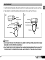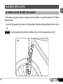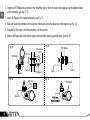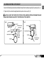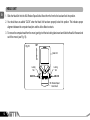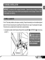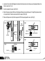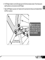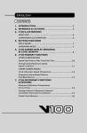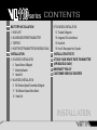
1
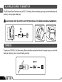
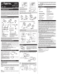
series CONTENTS
1 BATTERY INSTALLATION
1 HEAD UNIT
2 WL WIRELESS SPEED TRANSMITTER
2 TORPEDO
3 HEART RATE TRANSMITTER (HR MODELS ONLY)
4 INSTALLATION
4 HD MODELS INSTALLATION
4 Speed Sensor & Magnet
7 Mounting Bracket
8 Head Unit
9 WL MODELS INSTALLATION
9 WL Wireless Speed Transmitter & Magnet
11 WL Wireless Speed Active Mount
12 Head Unit
21
22
23
24
13 T2X MODELS INSTALLATION
13 Torpedo & Magnets
18 Integrated T2x Active Mount
19 Head Unit
19 How To Recognize Your Torpedo
INSTALLATION TESTS
ATTACH YOUR HEART RATE TRANSMITTER
(HR MODELS ONLY)
WARRANTY POLICY
CUSTOMER SERVICE CENTERS
INSTALLATION
IMPORTANT
● The Vetta’s VL110 series SmartLite Cycle Computers are sophisticated electronic
instruments. Vetta recommends that these products be installed only by a qualified bicycle
retailer. Failure to read these instructions and/or improper installation of this device may
void the warranty. If in doubt about any aspect of the installation of this product, consult
your local bicycle retailer for clarification.
● Always follow the sections that are marked with “
”
● Specifications and design are subject to change for improvement without notice.
● If you have any questions or concerns about this manual, please contact ACUMEN INC
at www.vetta.com.
BATTERY INSTALLATION
EN
HEAD UNIT
The VL110 series Head Units use CR2450, 3-Volt Lithium button cell batteries.
Important Most cycle computer problems are caused by weak or dead batteries. See the Trouble Shooting section near the
end of OPERATION MANUAL for details.
L
T
CE
3VO
LL
24
CR 50
LIT HIU M
1. Remove the battery cap from the bottom of the computer using a coin.
2. Install a new battery as shown with the positive (+) side facing out. Do not touch or bend any of the battery contacts
during installation.
3. Screw the battery cap firmly into place making sure the O-ring seal does not get pinched or distorted.
CAUTION: TO AVOID DAMAGE TO THE BATTERY CAP, DO NOT OVER TIGHTEN.
1
WL WIRELESS SPEED TRANSMITTER
EN
The WL Wireless Speed Transmitter uses an A23, 12-Volt battery. Remove the battery cap using a coin and install battery with
positive (+) side up, replace battery cap.
CAUTION: MAKE SURE THE BATTERY CAP IS PROPERLY INSTALLED TO INSURE GOOD SIGNAL TRANSMISSION.
TORPEDO
Torpedo uses a CR123A, 3-Volt Lithium battery. Remove the battery cap from the bottom of the torpedo using a coin and install
battery with positive (+) side in, screw the battery cap firmly.
CR123A
2
HEART RATE TRANSMITTER (HR MODELS ONLY)
EN
The Vetta’s Heart Rate Transmitter uses either a CR2050 or a CR2032 with a rubber shim, both of them are 3-Volt Lithium
button cells and included.
Important For a CR2032 battery, make sure install the rubber shim into the battery cap first before put the battery cap back.
CAUTION: TO AVOID DAMAGE TO THE BATTERY CAP, DO NOT OVER TIGHTEN.
or
CR2050
CR2032
Rubber Shim
Battery Cap
3
INSTALLATION
EN
HD MODELS INSTALLATION
SPEED SENSOR & MAGNET
1. Use the Zip-Tie supplied to hold loosely the Wired Speed Sensor and Bracket Mounting Pad to the inside of either fork leg.
We recommend mounting it as high up on the fork leg as possible to protect it from being hit by rocks, branches or other
objects while riding. (see Fig. 1)
Fig. 1
4
2. Tighten the SPD Magnet to any spoke on the “sensor side” of the front wheel so that it passes over the Alignment Mark on the
sensor. (see Fig. 1, 2)
EN
3. Attach the Spacer to the magnet temporarily. (see Fig. 3)
4. Slide and rotate the sensor until the Alignment Mark just touches the Spacer tip on the magnet. (see Fig. 4)
Fig. 2
SPD Magnet
Magnet Sweep Path
Zip-Tie
SPD Magnet
Spoke
Fork Leg
Wired Speed Sensor
SPD Magnet
Fig. 3
Fig. 4
Spacer Tip
Spacer
Spoke
Alignment Mark
5
5. Route the sensor wire up the fork blade and secure it with the tape. Wrap excess wire around the front brake cable housing,
leaving enough slack to attach the Mounting Bracket easily to the handlebar and allow for movement of the bar and stem.
EN
CAUTION: WHEN INSTALLING THE SPEED SENSOR ON A SUSPENSION FORK, MAKE SURE THAT THE FORK
IS FULLY EXTENDED TO ENSURE THERE IS ENOUGH WIRE TO REACH THE MOUNTING BRACKET PROPERLY.
EXCESS SENSOR WIRE SHOULD BE TAPED DOWN OR WRAPPED AROUND THE BRAKE CABLE HOUSING FOR
SAFETY.
6. Snug the Zip-Tie down to hold the sensor in its final position.
7. Remove the Spacer and verify that the magnet and sensor spacing stayed the same. (see Fig. 5)
Fig. 5
SPD
Magnet
Wired Speed
Sensor
Important Do not use a Zip-Tie tightening tool or a third hand tool when doing the final tensioning of the Zip-Ties. This can
tear and damage the sensor.
6
MOUNTING BRACKET
EN
1. Install the Wired Mounting Bracket and Bracket Mounting Pad to the handlebar using the Zip-Ties provided. (see Fig. 6)
2. Tighten the Zip-Ties so that the Mounting Bracket holds its position on the bar. (see Fig. 7) Trim excess.
Fig. 7
Fig. 6
Head Unit
Mounting Bracket
Head Unit
Mounting Bracket
Bracket Rubber Pad
Bracket Rubber Pad
Zip-Tie
Zip-Tie
Handlebar
Handlebar
CAUTION:
1. DO NOT USE ZIP-TIES BUT TAPES PROVIDED TO HOLD WIRES TO THE FRAME, FORK, BARS OR STEM TO AVOID
DAMAGING OR CUTTING THE WIRES ACCIDENTALLY.
2. DO NOT OVER TIGHTEN THE ZIP-TIES BECAUSE THIS CAN BEND THE MOUNTING BRACKET, WHICH CAN AFFECT
THE OPERATION OF THE COMPUTER ITSELF AS WELL AS THE SECURITY OF THE HEAD UNIT IN THE MOUNT.
7
HEAD UNIT
EN
1. Slide the Head Unit into the Mounting Bracket from the front to the back and lock into position.
2. You should hear an audible “CLICK” when the Head Unit has been properly locked into position. This indicates proper
alignment between the computer head pins and the Mounting Bracket contacts.
3. To remove the computer head from the bracket, gently pinch the two locking tabs inward and slide the Head Unit forward
and out of the bracket. (see Fig. 8)
Fig. 8
OUT
Head Unit
IN
Locking
Tab
UNLOCK
Locking
Tab
UNLOCK
Mounting Bracket
8
WL MODELS INSTALLATION
EN
WL WIRELESS SPEED TRANSMITTER & MAGNET
The WL models are designed to operate as a wireless unit with the installation of a special Active Mount and WL Wireless
Speed Transmitter.
1. Use the Zip-Ties supplied to hold loosely the WL Wireless Speed Transmitter and Mounting Bracket Pad to the left fork
leg.
Important To maximize signal reception, position the transmitter as high up on the fork leg as possible. (see Fig. 9)
Fig.9
9
2. Tighten the SPD Magnet to any spoke on the “transmitter side” of the front wheel so that it passes over the Alignment Mark
on the transmitter. (see Fig. 9, 10)
EN
3. Attach the Spacer to the magnet temporarily. (see Fig. 11)
4. Slide and rotate the transmitter until the Alignment Mark just touches the Spacer tip on the magnet. (see Fig. 12)
5. Snug the Zip-Ties down to hold the transmitter in its final position.
6. Remove the Spacer and verify that the magnet and transmitter spacing stayed the same. (see Fig. 13)
Fig. 11
Fig. 10
Zip-Ties
SPD Magnet
Fork Leg
Spoke
Fig. 12
Alignment
Mark
Spacer Tip
10
SPD Magnet
Magnet Sweep
Path
Spoke
SPD Magnet
Spacer
Fig. 13
SPD Magnet
WL WIRELESS SPEED ACTIVE MOUNT
EN
1. Attach the WL Wireless Speed Active Mount and Bracket Mounting Pad to the handlebar using the Zip-Ties provided (see Fig. 14).
2. Tighten the Zip-Ties so that the Mounting Bracket holds its position on the bar. (see Fig. 15).
CAUTION: DO NOT OVER TIGHTEN THE ZIP-TIES ON THE WL WIRELESS SPEED ACTIVE MOUNT BECAUSE
THIS MAY BEND THE MOUNT AND AFFECT THE OPERATION OF THE COMPUTER.
Fig. 14
Fig. 15
Head Unit
WL Wireless Speed
Active Mount
Head Unit
Bracket Rubber Pad
Zip-Tie
Bracket Rubber Pad
Handlebar
Handlebar
Zip-Tie
WL Wireless Speed
Active Mount
11
HEAD UNIT
EN
1. Slide the Head Unit into the WL Wireless Speed Active Mount from the front to the back and lock into position.
2. You should hear an audible “CLICK” when the Head Unit has been properly locked into position. This indicates proper
alignment between the computer head pins and the Active Mount contacts.
3. To remove the computer head from the mount, gently pinch the two locking tabs inward and slide the Head Unit forward and
out of the mount. (see Fig. 16)
OUT
Fig. 16
Head Unit
IN
Locking
Tab
UNLOCK
Locking
Tab
UNLOCK
WL Wireless Speed
Active Mount
12
T2X MODELS INSTALLATION
EN
IMPORTANT: The computer can ONLY recognize the transmitter — Torpedo after they go through the ID Learning
procedure. This feature makes the computer suitable for group training without cross talk. (see page 19, Section of HOW
TO RECOGNIZE YOUR TORPEDO)
TORPEDO & MAGNETS
For the 1st time battery installation (or after replace a new battery), Torpedo will automatically turn on the installation alignment
function for 5 minutes. During this period, the Light Ring of the Torpedo will turn on in green if receiving inputs from magnets.
This function can be re-activated when the Torpedo button is pressed momentarily.
1. Use the Zip-Tie provided to hold the Torpedo and Torpedo Shim loosely ABOVE A or UNDERNEATH B the left chain-stay
(see Fig.17).
Fig.17
WARNING: TO AVOID THE
SPD ARM BEING BROKEN BY
THE SPINNING SPOKE, MAKE
SURE THE SPD ARM ALWAYS
POINTING DOWNWARD.
A
B
CAD Magnet Mounted
Inside of Crank Arm
13
2. Use the Zip-Tie to hold the CAD Magnet to the inside of the left crank arm so that it will pass over the Alignment Mark on the
CAD Arm. (See Fig.17 & 18)
EN
3. Cover the magnet by the spacer. (See Fig.19)
4. Slide the Torpedo and rotate CAD Arm until the Alignment Mark just touches the Spacer tip. The Light Ring Indicator will turn
on in green when the Torpedo receives input from the magnet. (See Fig.20)
5. Remove the Spacer and verify that the magnet and CAD Arm spacing stayed the same. (See Fig.21)
CAD Arm
Fig.20
Chain Stay
CAD
Magnet
Crank Arm
Magnet
Sweep Path
Alignment
Address Learning
Fig.18
CAD Arm
SPD Arm
Spacer Tip
Zip-Ties
Light Ring Indicator
CAD
Magnet
CAD Magnet
Fig.19
Crank Arm
14
Alignment
Address Learning
Fig.21
Spacer
CAD Arm
CAD Magnet
6. For SPD Magnet installation, move the CAD magnet away from CAD Arm by turning the crank arm. This will make sure the
Light Ring indicator can only be turned on by the SPD Magnet.
EN
7. Tighten the SPD Magnet to any spoke on the ‘Torpedo side’ of the rear wheel so that it will pass over the Alignment Mark of
the SPD Arm. (see fig.22)
Fig.22
WARNING: TO AVOID THE
SPD ARM BEING BROKEN BY
THE SPINNING SPOKE, MAKE
SURE THE SPD ARM ALWAYS
POINTING DOWNWARD.
A
B
SPD Magnet Mounted
Any Spoke of the Rear Wheel
15
9. Repeat Step 3 to Step 6. (see Fig.25 to Fig.28)
EN
Fig.25
Magnet
Sweet
Path
Fig.27
Spacer Tip
SPD Magnet
Zip-Ties
SPD Arm
Alignment
Address Learning
Light Ring Indicator
CAD Arm
Alignment
Address Learning
SPD Magnet
SPD Arm
Spoke
Fig.28
Fig.26
SPD Magnet
Alignment
Address Learning
SPD Magnet
Spoke
Spacer
10. Snug the Zip-Ties down to hold the Torpedo in its final position.
16
8. TO AVOID THE SPD ARM BEING BROKEN BY THE SPINNING SPOKE, MAKE SURE THE SPD ARM ALWAYS
POINTING DOWNWARD. (see Fig.23 & Fig.24)
EN
Underneath the Chain-Stay
Above the Chain-Stay
Fig. 23
Fig. 24
Chain-Stay
D
A
C
CAD Arm
E
N
C
E
C
S
P
E
E
D
A
D
E
CAD Arm
N
C
E
SPD Arm
ay
Chain-St
S
P
E
E
D
SPD Arm
17
INTEGRATED T2X ACTIVE MOUNT
EN
Please follow the same procedure described before (see page 11, Section of WL WIRELESS SPEED ACTIVE MOUNT).
CAUTION: DO NOT OVER TIGHTEN THE ZIP-TIES ON THE INTEGRATED T2X ACTIVE MOUNT BECAUSE THIS
MAY BEND THE BRACKET AND AFFECT THE OPERATION OF THE COMPUTER.
Fig. 29
Fig. 30
Head Unit
Integrated T2X
Active Mount
Head Unit
Bracket Rubber Pad
Zip-Tie
Bracket Rubber Pad
Handlebar
Zip-Tie
Handlebar
18
Integrated T2X
Active Mount
HEAD UNIT
EN
Please follow the same procedure described before (see Page 12, Section of HEAD UNIT OF WL MODELS INSTALLATION)
Fig. 31
OUT
Head Unit
IN
Locking
Tab
UNLOCK
Locking
Tab
UNLOCK
Integrated T2X
Active Mount
HOW TO RECOGNIZE YOUR TORPEDO
1. If your Torpedo is purchased as a complete set with the VL110 series computer, your computer has been programmed to
recognize the Torpedo in the factory.
2. If a new Torpedo or Integrated T2X Active Mount is purchased for replacement, please follow the ID Learning Procedure.
3. If a complete set of Integrated T2X Mounting Kit is purchased for your 2nd bike, please make sure you had chosen Bike II in the
NOM Setup mode (see page 11 of the OPERATION MANUAL , Section of Dual Bike in NOM Setup), and follow the ID Learning
Procedure.
19
ID LEARNING PROCEDURE
EN
Step 1: Install the computer on the Integrated T2X Active
Mount.
Step 2: After the screen display “id NEEd”, press & hold
the Torpedo’s button for 3 seconds.The Light Ring
Indicator of the Torpedo will turn on for 2 seconds
in red.
Button
Button
1
Step 3: During the process, the computer will display “id
LEArn” for 3 seconds.
Button
4
Button
2
3
Step 4: When done successfully, the computer will display “id donE” and gives 2 short beeps. The
computer will go back to the screen last displayed.
FAILURE
If the computer always displays “id NEEd”, you should check the alignments and spacings between
the magnets and Torpedo and make sure that the Head Unit is completely snapped into position.
If these checks do not solve the problem, talk to an authorized Vetta’s Retailer or connect to www.
vetta.com.
Important To re-activate the ID Learning Procedure, press & hold
seconds with RT/TT timers are off.
20
2
&
4
simultaneously for 2
INSTALLATION TESTS
EN
Once installation is completed, the computer should be tested to make sure it is working properly.
To Test Sensor/Transmitter Installation (HD/WL models):
1. Advance the computer to the RT/TT Mode by using Button 2 .
2. Make sure the RT/TT timers are running, or reset to zero by press & hold Button 3 .
3. Advance the computer to the SPD/DST Mode by using Button 2 .
4. Pick up the front of the bicycle and spin the front wheel. The computer should display a speed-reading within 2-3 seconds.
If there is no speed reading, check the alignment and spacing between the magnet and sensor/transmitter and make sure that
the head unit is completely snapped into position. If these checks do not solve the problem, talk to an Authorized Vetta’s Retailer
or connect to www.vetta.com.
To Test Torpedo Installation (T2X models):
1.
2.
3.
4.
Advance the computer to the RT/TT Mode by using Button 2 .
Make sure the RT/TT timers are running, or reset to zero by press & hold Button 3 .
Advance the computer to the SPD/CAD Mode using Button 2 .
Ride the bicycle a short distance, after a few revolutions, a speed-reading and a cadence reading should appear on the
display. If there is no speed or cadence reading, check the alignment and spacing between the magnets and Torpedo.
Important Make sure the magnets locking screw and all Zip-Ties are properly tightened.
Tips: Rotating the angle of the transmitters or the handlebar receiver (slightly), can sometimes improve the signals being
sent and received. Some bicycles have unusual frame tubes and angles, so by adjusting the components, can aid in
trouble shooting by aligning the misdirected signals.
21
ATTACH YOUR HEART RATE TRANSMITTER (HR MODELS ONLY)
EN
1. Moisten the transmitter electrodes by applying a small drop of water on each of the two contact areas. (see Fig.32)
2. Attach the adjustable Chest Strap to HR Transmitter. Insert round end of clip through the hole and twist gently. (see Fig.33)
3. Strap the HR Transmitter around your chest.
4. Adjust the tension of the Chest Strap to fit snugly, but comfortably around your chest. (see Fig.34)
Important When the computer receiving signals from HR Transmitter, the each of the screen displays will show Heart Rate
reading and the blinking heart icon. If not, make sure the correction installation.
Fig. 33
Fig. 32
Electrode
Fig. 34
or
22
WARRANTY POLICY
EN
ACUMEN INC. WARRANTS ALL VETTA (The Company) PRODUCTS AGAINST MANUFACTURER DEFECTS FOR A
PERIOD OF 3 YEARS. Subject to the following limitations, terms and conditions, components will be free of manufacturing
defects in materials and workmanship. The 3 year limited warranty is conditioned upon the components being used and
operated in normal riding conditions. This warranty does not cover normal wear and tear (i.e. battery replacement, broken
wire), rider abuse, acts of God, improper installation or product alteration. This warranty is void if the components were not
purchased (new) from or through an authorized VETTA retailer or dealer, examples of unauthorized dealers are online
auction sites or online retailers that do not offer service.
ACUMEN INC. at its sole discretion will repair or replace items at its own cost. Users are responsible for all freight and shipping
charges, when returning items for warranty service.
ACUMEN INC. will pay the freight when returning serviced items, via USPS or UPS to consumers or dealers, once the item(s)
has been repaired or replaced.
REQUIREMENTS FOR WARRANTY SERVICING
1. Prior to shipping an item back, you must first obtain a Return Authorization Number (s) (RA#). Each item being returned
must have an individual RA#.
2. To obtain an RA #, you must either contact the retailer where the product was originally purchased from, or contact VETTA
directly at [email protected].
3. For trouble shooting purposes, we request that the complete unit with packaging be returned to ACUMEN INC. unless
otherwise stated by VETTA representative.
23
ITEMS TO BE INCLUDED IN RETURNS
EN
1.
2.
3.
4.
5.
The defective product(s)
A letter clearly stating the problem(s) with the returned item(s).
Copy of the original sales receipt showing proof of purchase date.
The Company is not responsible for loss or additional damages while in transit to ACUMEN INC.
Clearly mark the RA# on the outside of the return packaging. All items without an RA # will be refused and returned to the
return address on the package.
The Company shall not be held responsible for replacing items with new items for greater than the amount of the original item
purchase price. This limited warranty does provide the original owner with certain legal rights and recourse. The original owner
may possess other rights or recourse, depending on the state or country. Please check the web to help answer any question
and service manual.
CUSTOMER SERVICE CENTERS
Acumen Inc.
101A Executive Dr., Suite 100, Sterling, VA 20166, USA.
Acumen Europe BV
Splijtbakweg 117, 1333 HJ, Almere, The Netherlands.
E-Mail: [email protected]
Website: www.vetta.com
24