1
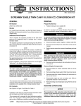
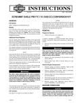
-J04480
REV. 2015-04-23
SCREAMIN' EAGLE "HEAVY BREATHER" PERFORMANCE AIR
CLEANER KIT
GENERAL
NOTE
Kit Numbers
See a Harley-Davidson dealer for ECM (Electronic Control
Module) calibration.
29264-08, 29080-09
Kit Contents
Models
For model fitment information, see the P&A Retail Catalog or
the Parts and Accessories section of www.harley-davidson.com
(English only).
See Figure 1 and Table 1.
INSTALLATION
NOTE
These kits are intended for High Performance applications
only. Engine-related performance parts are intended FOR THE
EXPERIENCED RIDER ONLY.
To prevent accidental vehicle start-up, which could cause
death or serious injury, disconnect battery cables (negative
(-) cable first) before proceeding. (00307a)
Additional Parts Required
LOCTITE® 243 (Blue) Threadlocker and Sealant is needed for
proper installation of this kit. A 0.5 mL pack of Loctite 243 is
included with this kit. A 6.0 mL tube (99642-97) is available
from a Harley-Davidson dealer.
Air filter oil is also needed for proper installation of this kit.
K&N® Air Filter Oil is available from a Harley-Davidson dealer,
either alone (12.25 oz/347 gram aerosol can, 99882-88T) or
in a 6.5 oz/184 gram aerosol can as part of the Filter Care
Service Kit (99850-92T).
Proper installation of this kit requires breather screws (3565),
which are OE equipped on 2004 and later XL models. If the
motorcycle is not equipped with these breather screws, separate purchase is required.
The rider's safety depends upon the correct installation
of this kit. Use the appropriate service manual procedures.
If the procedure is not within your capabilities or you do
not have the correct tools, have a Harley-Davidson dealer
perform the installation. Improper installation of this kit
could result in death or serious injury. (00333a)
NOTES
This instruction sheet references service manual information.
A service manual for your model motorcycle is required for this
installation and is available from a Harley-Davidson dealer.
Disconnect negative (-) battery cable first. If positive (+)
cable should contact ground with negative (-) cable connected, the resulting sparks can cause a battery explosion,
which could result in death or serious injury. (00049a)
1.
When servicing the fuel system, do not smoke or allow
open flame or sparks in the vicinity. Gasoline is extremely
flammable and highly explosive, which could result in
death or serious injury. (00330a)
Original Equipment (OE) Air Cleaner Removal
For carbureted models: Refer to the service manual and
check the warm-slow idle speed adjustment before removing
the OE air cleaner backplate.
For EFI (fuel-injected) models: Have a Harley-Davidson
dealer recalibrate the ECM prior to air cleaner installation.
2.
Remove the air cleaner backplate following the instructions
in the service manual. Retain the two breather screws (A)
removed from the backplate (see Figure 1). The remaining
parts can be discarded.
3.
See Figure 1. Remove and discard induction module
bracket (B).
The following caution and note apply to EFI models only.
You must recalibrate the ECM when installing this kit.
Failure to properly recalibrate the ECM can result in severe
engine damage. (00399b)
-J04480
Refer to the service manual and follow the instructions
given to remove the seat and disconnect the battery
cables, negative (-) cable first. Save all seat mounting
hardware.
"Heavy Breather" Air Cleaner Installation
NOTE
When servicing the air cleaner, apply Loctite 243 (blue) to all
threaded fasteners (both male and female threads).
1 of 5
Many Harley-Davidson® Parts & Accessories are made of plastics and metals which can be recycled.
Please dispose of materials responsibly.
4.
See Figure 1. Install the new O-rings (4) in the grooves
around the breather screw holes on the carburetor or
induction module side of the backplate (1 or 2).
17. Remove the air filter element (19) and band clamp (15)
from the package. Loosen the band clamp as needed to
allow removal or repositioning.
5.
Remove the backing from the adhesive side of the backplate gasket (3). Carefully align the holes and install the
gasket on the carburetor or induction module side of the
backplate.
NOTES
For proper adhesion, degrease the area on the backside of
the filter element where the adhesive ring will be mounted.
Note the Screamin' Eagle® logo on the chrome filter element
end cap. For best appearance, install the band clamp and
chrome band clamp cover onto the filter element flange so the
screw slot will be accessible but the screw mechanism hidden
from view when the filter is installed to the intake tube with the
logo upright.
6.
Insert the breather screws (removed in Step 2) through
the backplate. Apply a small amount of Loctite (9) to the
breather screw threads and the mating tapped holes in
the cylinder head, then install the screws into the cylinder
head. DO NOT tighten completely at this time.
7.
Obtain the three backplate mounting screws (5) from the
kit, and apply a small amount of Loctite to the screw
threads. Install the screws all the way through the backplate and gasket until the screw threads are captured in
the carburetor or induction module. DO NOT tighten
completely at this time.
18. Remove the backing from the remaining side of the
adhesive ring and press the chrome band clamp cover
onto the large end of the air filter element.
8.
Alternately tighten the two breather screws to 120-144 inlbs (13.6-16.3 Nm).
9.
Lubricate the O-rings (6) with clean engine oil or white
lithium grease.
19. Install the air filter element onto the intake tube approximately 5/8 inch (16 mm). Check that the filter element end
cap logo is upright, and the band clamp screw mechanism
is hidden from view, yet the screw slot is accessible for
tightening.
Install the O-rings onto the breather plugs (10). Press the
breather plugs into the breather screw cavities.
10. Tighten the three backplate mounting screws to 55-60 inlbs (6.2-6.8 Nm).
Position the band clamp onto the filter element flange,
inside the chrome cover flange with the band clamp screw
mechanism in the cover flange cutout.
Tighten the clamp around the filter element flange to 30-40
in-lbs (3.4-4.5 Nm).
20. Install the rain sock (19) over the air filter element.
Air Filter Element and Air Tube Installation
NOTE
This air filter is PRE-OILED and ready to install.
11. With the countersunk holes facing outward, slide the
mounting ring (13) all the way onto the intake tube (12),
up to the flange.
12. Place the gasket (7) against the opposite side of the
flange.
Connect positive (+) battery cable first. If positive (+) cable
should contact ground with negative (-) cable connected,
the resulting sparks can cause a battery explosion, which
could result in death or serious injury. (00068a)
21. Refer to the service manual and follow the instructions
given to connect the battery cables, positive (+) cable first,
and install the seat.
13. Align the holes in the gasket with the mounting ring holes
and notches in the intake tube flange.
14. Apply a small amount of Loctite to the threads of the three
flat head screws (8).
15. Secure the intake tube, mounting ring and gasket to the
air cleaner backplate, and tighten the screws to 55-60 inlbs (6.2-6.8 Nm).
16. Remove the backing from one side of the adhesive ring
(17), center the ring on the inner surface of the band clamp
cover (16) and press the ring evenly and firmly into place.
-J04480
After installing seat, pull upward on seat to be sure it is
locked in position. While riding, a loose seat can shift
causing loss of control, which could result in death or
serious injury. (00070b)
NOTES
Riding a motorcycle equipped with an exposed oiled air filter
under rainy conditions IS NOT RECOMMENDED.
Install the rain sock (19) over the air filter element under these
circumstances.
2 of 5
AIR FILTER ELEMENT MAINTENANCE
2.
NOTES
Riding a motorcycle equipped with an exposed oiled air filter
under rainy conditions IS NOT RECOMMENDED.
To clean the element:
a.
Loosen the hose clamp retaining the air filter element
assembly to the air tube. Separate the element from
the air tube.
b.
Tap the element to dislodge any loose dirt, then gently
brush with a soft bristle brush.
c.
Spray air filter cleaner liberally onto the cotton filter
media and let soak for ten minutes, OR
Install the rain sock (19) over the air filter element under these
circumstances.
1.
Inspect the air filter element every 5000 miles (8000 km),
or more often under dusty conditions.
roll or soak the cotton filter media in a shallow pan of
air filter cleaner. Remove immediately, and let soak
for ten minutes.
NOTES
The use of cleaning, drying or oiling methods or products other
than those shown will damage the filter and void the manufacturer's warranty.
K&N® Air Filter Cleaner is available from a Harley-Davidson
dealer, either alone (1 qt./0.95 L sprayer bottle, 99883-88T) or
a 12 fl oz/0.35 L sprayer bottle as part of the Filter Care Service
Kit (99850-92T).
K&N Air Filter Oil is also available from a Harley-Davidson
dealer, either alone (12.25 oz/ 347 gram aerosol can, 9988288T) or a 6.5 oz/ 184 gram aerosol can as part of the Filter
Care Service Kit.
d.
Rinse off the filter media (flowing from the clean side
to the dirty side), with low-pressure tap water.
e.
After rinsing, shake off all excess water, and let the
filter media air dry. DO NOT use compressed air or
a heat gun to speed drying.
f.
After the filter media is completely dry, EITHER
spray air filter oil along each pleat, once only, holding
the spray nozzle approximately 3 inches (76 mm)
away from the media, OR
carefully use a squeeze bottle to deposit oil along
each pleat, once only.
DO NOT OVER-OIL THE AIR FILTER. Over-oiling may interfere with the proper performance of the engine and/or certain
engine components. If oil is still draining or dripping from the
filter media twenty minutes after oiling, clean and oil the filter
element again.
Let the oil absorb into the filter media for twenty
minutes before proceeding.
After twenty minutes, inspect the filter media, and
carefully apply oil to any remaining visible white spots
on the filter media, and allow to absorb.
3.
Install the air filter element onto the intake tube approximately 5/8 inch (16 mm). Check that the filter element end
cap logo is upright.
Tighten the clamp around the filter element flange to 30-40
in-lbs (3.4-4.5 Nm).
-J04480
3 of 5
SERVICE PARTS
is03087e
B
3
4
4
6
7
1
5
A
2
6
11
19
9
10
12
18
A
13
8
10
14
15
16
17
Figure 1. Service Parts: Air Cleaner Kit
Table 1. Service Parts Table
Item
Description (Quantity)
Part Number
1
Backplate, air cleaner , chrome
29760-05
2
Backplate, air cleaner , black
28888-09
3
Gasket, backplate to carburetor or induction module
29059-88A
4
O-ring, backplate (2)
11292
5
Screw, backplate mounting (3)
926
6
O-ring, breather plug (4)
10925
7
Gasket, intake tube to backplate
29593-05A
8
Screw, flat head (3)
2986
9
Loctite 243 (blue) Threadlocker and Sealant (0.5 mL tube)
94635-98
10
Plug, breather (2)
29830-05A
11
Intake tube and mounting ring service kit, chrome only (includes items 12 and 13)
29571-08
12
•
Not sold separately
13
14
-J04480
Intake tube, chrome
Intake tube, black
28817-09
•
Not sold separately
Mounting ring, chrome
Mounting ring, black
29070-09
Air cleaner filter kit (includes items 15 through 19)
29424-05A
4 of 5
Table 1. Service Parts Table
Item
Description (Quantity)
Part Number
15
•
Band clamp
Not sold separately
16
•
Cover, band clamp (chrome)
Not sold separately
17
•
Adhesive ring
Not sold separately
18
•
Element, air filter (includes item 15)
Not sold separately
19
Rain sock, air filter
29493-05
Items mentioned in text, but not included in kit:
A
Original equipment breather screw (2)
B
Induction module bracket (remove and discard)
-J04480
5 of 5