1
GENUINE PARTS
INSTALLATION INSTRUCTIONS
1 DESCRIPTION:
2 APPLICATION:
3 PART NUMBER(S)
REQUIRED FOR
INSTALLATION:
Remote Engine Starter
Altima MY 13-15
999K1 UZ000 Remote Engine Start Kit (w/o RES w/ Factory Hd Lk Sw)
999K1 UZ001 Remote Engine Start Kit (w/o Factory RES & w/o Factory Hd Lk Sw)
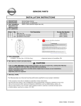
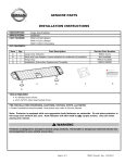
(999K1 UZ001 Kit is shown below)
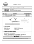
4 KIT CONTENTS:
Item
A
B
C
D
E
A
Qty.
2
1
1
1
N/A
Part Description
Key Fob (L/UL/PN/RES)
Lock Assy-Hood
Harness Clip
II Replacement Template
Installation Instructions
B
5 TOOLS REQUIRED:
● CONSULT III plus
● Approved access to Immobilizer PIN
● 10 mm Racheting wrench
Service Part Number
285E3 3TP5A
65601 3TA0A
24346 C9960
999V2 AW000
999K1 U3000II
C
D
● Low profile head 3/8" torque wrench
● Short 10 mm 3/8" socket
● China marker or Grease pencil
6 PRE-INSTALLATION CAUTION/NOTES:
CAUTION
● DEALER INSTALLATION ONLY, these installation instructions refer to the service manual.
● This is a ONE TIME ONLY programming procedure. Be sure to acquire ALL existing Non-RES key
fobs from customer and the new RES key fobs before proceeding.
● Please read these instructions carefully before beginning to ensure correct installation.
● Specialty tools are required.
7 CRITICAL STEPS:
The following steps are critical and must be performed as specified to ensure proper installation:
●
●
●
●
Do Not place key fob(s) on top of dashboard during programming. Frequency interference may occur.
Be sure to avoid any other sources of frequency interference such as walkie-talkies, radios, etc.
Be sure that vehicle is out of transit mode (shipping mode) by pushing in extended storage switch.
Vehicle battery must be at or above 12.5 VDC.
Page 1
999K1 U3000 II 08/10/2015
INSTALLATION INSTRUCTIONS
8 Vehicle Preperation:
CAUTION
● Always confirm the ignition is in the "OFF" position before changing the E.S.S. position.
1)
2)
Apply parking brake
Confirm vehicle is no longer in default shipping state (Extended Storage Switch Pulled Up and BCM in
Transit Mode). Failure to confirm vehicle has been removed from this state will result in loss of normal
vehicle operation. Confirmation requires two checks:
Fig. 1
3)
Locating Extended Storage Switch.
a) Locate Extended Storage Switch in cabin
fuse block.
b)
Fig. 2
4)
Engage and remove from transit mode
a) To engage transit mode, pull out in A direction as
shown in the figure.
b)
A
Check Extended Storage Switch is in
"Customer" position as shown in Fig. 1.
To remove from transit mode, press in B
direction as shown in the figure.
B
Condition
Switch Position
Note
Vehicle is delivered to the dealer
Inventory Condition
Technician performs PDI
Customer Delivery
Return to Inventory position after PDI.
Customer test drives the vehicle
Customer Delivery
Return to Inventory position after test drive.
Vehicle is being stored at the dealer
Inventory Condition
Vehicle is delivered to customer
Customer Delivery
5) Turn ignition switch to "ON" position
6) Record the customer radio presets and other presets as required.
Preset
1
2
3
4
5
6
7)
8)
9)
Put shift lever in "P" position for A/T and CVT or "1st" for M/T
Turn ignition switch to "OFF" position
Use seat and floor protection.
Page 2
999K1 U4000 II 08/10/2015
INSTALLATION INSTRUCTIONS
9 Vehicle Preperation:
a.) Install new hood switch
b.) Connect tool.
c.) Locate OBD connector.
d.) Connect tool.
e.) Follow CONSULT III programming instructions.
f.) Verify RES operation.
10 Installation Procedure: Cautions / Notes
CAUTION
● Do not allow the Intelligent Key, which contains electrical components, to come into contact with
water. This could severely affect system function. If the Intelligent Key gets wet, immediately wipe
moisture from I-Key until completely dry.
● Do not drop the Intelligent Key.
● Do not strike the Intelligent Key sharply against another object.
● Do not change or modify the Intelligent Key.
● Do not place the Intelligent Key in an area where temperatures exceed 140°F (60°C) for any
extended period of time.
● Do not attach the Intelligent Key with a key holder that contains a magnet.
● Take care not to scratch or damage any component during the installation process.
● Always follow the sequence of steps as they are shown, improper procedure can damage parts
and/or systems.
● Be sure ALL key fobs for this vehicle have been acquired before proceeding.
● Avoid All other sources of frequency interference such as cell phones, walkie-talkies, radios, etc…
● Do not stop or disconnect CONSULT III plus or VI until after the process has been completed.
● Dispose of old (original) key fobs once the RES installation process has been completed. DO NOT
use fobs again and DO NOT return to customer.
● The following steps are for reference only.
● Follow procedure EXACTLY as directed in Service Manual Sect K: DLK: Removal and Installation of
Hood Lock Control.
11 Installation Overview
1.) SYSTEM
Fig. 3
Page 3
999K1 U4000 II 08/10/2015
INSTALLATION INSTRUCTIONS
12 Installation Procedure: Vehicle Parts Installation
Fig. 4
1)
Removing hood lock assembly.
a) Locate hood lock control, under LH side of
lower panel LH as shown in Fig. 4.
b)
Pull hood lock control to release hood.
CAUTION
● The following steps are for reference only.
● Follow procedure exactly as directed in
Service Manual Sect K: DLK: Removal and
Installation of Hood Lock Control.
HOOD
LATCH
RELEASE
Fig. 5
2)
Removing hood lock assembly
a) Using 1/4 rachet and 10mm socket loosen
Negative battery terminal.
b)
Remove and isolate negative terminal from
negative post as shown in Fig. 5.
CAUTION
● Allow an additional 3 min after negative
terminal dis-connect before separating
any electrical connectors.
Fig. 6
3)
Removing hood lock assembly
a) Remove seven (7) clips from radiator core support
upper cover panel and set aside
for later reinstallation.
b)
Remove radiator core support upper cover panel as
shown in Fig. 6.
CAUTION
● Follow procedure exactly as directed in
Service Manual Sect K: DLK: Removal and
Installation of Hood Lock Control.
FRONT
OF
VEHICLE
Fig. 7
4)
Removing hood lock assembly
a) Loosen two (2) 10mm bolts from both ends
of air intake cover, bolts do not need to be
completely removed.
b)
Remove air intake cover as shown in Fig. 7.
CAUTION
● Follow procedure exactly as directed in
Service Manual Sect K: DLK: Removal and
Installation of Hood Lock Control.
FRONT
OF
VEHICLE
Page 4
999K1 U4000 II 08/10/2015
INSTALLATION INSTRUCTIONS
12 Installation Procedure: Vehicle Parts Installation
Fig. 8
5)
Removing hood lock assembly
a) Mark location of hood lock, prior to removal
with china marker or grease pencil.
b)
Using 12 mm Racheting wrench, remove three
(3) bolts and set aside as shown in Fig. 8.
CAUTION
FRONT
OF
VEHICLE
● Follow procedure exactly as directed in
Service Manual Sect K: DLK: Removal and
Installation of Hood Lock Control.
HOOD LOCK
ASSEMBLY BOLTS
Fig. 9
6)
CAUTION
HOOD
LOCK
RELEASE
CABLE
HOOD SWITCH PRE
WIRE CONNECTOR
Fig. 10
Removing hood lock assembly
a) Locate hood latch release cable on backside
of latch assembly and disconnect it as shown
in Fig. 9.
● Follow procedure exactly as directed in
Service Manual Sect K: DLK: Removal and
Installation of Hood Lock Control.
7)
Locating hood switch pre wire connector .
a) Pre-wired connector is located on left of hood
latch taped to harnessas shown in Fig. 10.
b)
Cut or tear tape holding connector to wire
harness.
b)
Remove sealing connector.
CAUTION
● Follow procedure exactly as directed in
Service Manual Sect K: DLK: Removal and
Installation of Hood Lock Control.
Fig. 11
8)
Installing hood lock assembly.
a) Connect hood release cable in back as shown
in Fig. 11.
CAUTION
● Follow procedure exactly as directed in
Service Manual Sect K: DLK: Removal and
Installation of Hood Lock Control.
HOOD
RELEASE
CABLE
Page 5
999K1 U4000 II 08/10/2015
INSTALLATION INSTRUCTIONS
12 Installation Procedure: Vehicle Parts Installation
Fig. 12
PRE WIRE
CONNECTOR
9)
Installing hood lock assembly.
a) Feed connector and harness from new latch
assembly through to left as shown in Fig. 10.
CAUTION
● Follow procedure exactly as directed in
Service Manual Sect K: DLK: Removal and
Installation of Hood Lock Control.
HOOD
SWITCH
CONNECTOR
Fig. 13
10)
Installing hood lock assembly.
a) Insert harness clip into base of pre wire connector
as shown in Fig. 13.
CAUTION
● Follow procedure exactly as directed in
Service Manual Sect K: DLK: Removal and
Installation of Hood Lock Control.
HARNESS CLIP
PRE WIRE
CONNECTOR
Fig. 14
11)
Installing hood lock assembly.
a) Rotate two connectors into position shown and snap
together as shown in Fig. 14.
CAUTION
● Follow procedure exactly as directed in
Service Manual Sect K: DLK: Removal and
Installation of Hood Lock Control.
HOOD
SWITCH
CONNECTOR
Fig. 15
12)
Installing hood lock assembly.
a) Press mounting clip into bracket hole to secure
connectors as shown in Fig. 15.
CAUTION
● Make sure all connectors being installed are
fully seated and locked before proceeding
with assembly process.
HARNESS CLIP
MOUNTING HOLE
Page 6
999K1 U4000 II 08/10/2015
INSTALLATION INSTRUCTIONS
12 Installation Procedure: Vehicle Parts Installation
Fig. 16
13)
Installing hood lock assembly.
a) Align hood lock assembly using marks made in step
5.
b)
c)
Hand start bolts as shown in Fig. 16.
Using low profile head torque wrench and short 12
mm socket Torque to 22 Nm.
CAUTION
● Follow procedure exactly as directed in
Service Manual Sect K: DLK: Removal and
Installation of Hood Lock Control.
HOOD LOCK
ASSEMBLY BOLTS
Fig. 17
14)
Connecting battery.
a)
Using 1/4 rachet and 10mm socket tighten
Negative battery terminal.
b)
Torque battery terminal nut to 5.4 Nm as
shown in Fig. 17.
CAUTION
● Allow an additional 5 min after negative
terminal dis-connect before separating any
electrical connectors.
CAUTION
● Perform the following steps to ensure that the hood latch is functioning properly.
UNIT: mm
HOOD
STRIKER
SECONDARY
STRIKER
UNIT: mm
Fig. 18
(B)
6.8
UNLOCK
(A)
LOCK
15)
SECONDARY
LATCH
20 + 1
SECONDARY
STRIKER
PRIMARY
LATCH
SECONDARY
LATCH
Installing hood lock assembly.
a) Operate hood lock release handle, carefully check that front end of hood assembly is raised and meets
specification provided (A). Confirm that hood lock release handle returns to original position as shown in Fig.
18.
b)
Make sure secondary latch properly engages with secondary striker when hood's own weight is dropped from
approx. 200 mm height. Confirm latch meets specification (B) as shown in Fig. 14.
c) Check that hood lock release handle operating force is 49 N (5.0 kg-f) or less.
d) Install so static closing force of hood assembly is 254 - 490 N (25.9 -50 kg-f).
NOTE: If hood lock assy requires additional adjustment refer to Service Manual Sect K: DLK:
HOOD LOCK ADJUSTMENT
Page 7
999K1 U4000 II 08/10/2015
INSTALLATION INSTRUCTIONS
12 Installation Procedure: Vehicle Parts Installation
OBD
CONNECTOR
Fig. 19
16)
Locating the connector.
a) Locate OBD Connector next to hood lock
control, under LH side of instrument lower panel LH
as shown in Fig. 19.
CAUTION
● Do Not place key fob(s) on top of dashboard
during programming. Frequency interference
may occur.
Fig. 20
Fig. 21
17)
18)
xxxxx
Connecting to the vehicle.
a) Press and hold Start Button for at least
2 seconds without depressing brake to put
vehicle in Key On / Engine Off.
b)
Connect CONSULT III plus tool to vehicle OBD
connector as shown in Fig. 20.
c)
Turn on hazard switch to prevent BCM from
entering into CAN communication sleep mode.
RES key fobs programming instructions.
a) Start CONSULT III plus make sure VI is
connected. VI serial number will appear
in the VI section and the VI status will
change to “Normal Mode” (green color)
as shown in Fig. 21.
b)
Fig. 22
19)
xxxxxxxx
Page 8
If VI is not connected to vehicle proceed to step 19.
If VI is connected go to step 23.
RES key fobs programming instructions.
a) If VI has not connected to vehicle click Select
VI/MI button to connect with the vehicle as
shown in Fig. 22.
999K1 U4000 II 08/10/2015
INSTALLATION INSTRUCTIONS
12 Installation Procedure: Vehicle Parts Installation
Fig. 23
20)
RES key fobs programming instructions.
a) Choose VI-2 detected as shown in Fig. 23.
b) Click "Connect" as shown in Fig. 23.
Fig. 24
21)
RES key fobs programming instructions.
a) Wait until update of the firmware of VI-2 is
completed as shown in Fig. 24.
Fig. 25
22)
RES key fobs programming instructions.
a) CONSULT III plus will changes to a home
screen automatically when procedure is
complete and VI-2 is connected on
Bluetooth as shown in Fig. 25.
b)
Fig. 26
23)
Page 9
Proceed to step 23 and continue with installation.
RES key fobs programming instructions.
a) Click "Immobilizer" as shown in Fig. 26.
999K1 U4000 II 08/10/2015
INSTALLATION INSTRUCTIONS
12 Installation Procedure: Vehicle Parts Installation
Fig. 27
24)
RES key fobs programming instructions.
a) A precaution screen will appear.
b) After you have finished reading all the precautions,
click "Next" as shown in Fig. 27.
Fig. 28
25)
RES key fobs programming instructions.
a) Click “Automatic Selection” as shown in
Fig. 28.
Fig. 29
26)
RES key fobs programming instructions.
a) Review the information on the confirmation
screen, if correct press click "Confirm" as
shown in Fig. 29.
Fig. 30
27)
RES key fobs programming instructions.
a) Once you click "Confirm" you will see a
system call menu as shown in Fig. 30.
Page 10
999K1 U4000 II 08/10/2015
INSTALLATION INSTRUCTIONS
12 Installation Procedure: Vehicle Parts Installation
Fig. 31
28)
RES key fobs programming instructions.
a) Once the system call is complete, you will enter the
Select Operation screen will as shown in Fig. 31.
b)
Fig. 32
29)
RES key fobs programming instructions.
a) Once you click “When performing key
registration” a new Contents of Operation
selection "Register Key" will be available as
shown in Fig. 32.
b)
Fig. 33
30)
Under OPERATION CATEGORY menu click
“When performing key registration” as
shown in Fig. 31.
Under Contents of Operation selection click
"Register Key" as shown in Fig. 32.
RES key fobs programming instructions.
a) Follow the CONSULT III plus prompts as
shown in Fig. 33.
CAUTION
● Do Not procede to Step 31 until the key
registery process has been completed.
Fig. 34
31)
New RES key fob confirmation.
a) From inside vehicle press Lock on Fob 1 and Unlock
on Fob 2 and confirm that vehicle responds
accordingly as shown Fig. 34.
b)
Page 11
From inside vehicle press Lock on Fob 2 and Unlock
on Fob 1 and confirm that vehicle responds
accordingly as shown Fig. 34.
999K1 U4000 II 08/10/2015
INSTALLATION INSTRUCTIONS
12 Installation Procedure: Vehicle Parts Installation
Fig. 35
32)
New RES key fob confirmation.
a) Press and hold push button Ignition switch
while depressing brake, to confirm vehicle
starts as shown in Fig. 35.
b)
Press push button Ignition switch and turn
ignition switch to OFF position as shown in
Fig. 35.
CAUTION
● Remove all Key Fobs from the vehicle, before
proceeding to the next step..
Fig. 36
33)
New RES key fob confirmation.
a) From outside vehicle press Lock on Fob 1 and
Unlock on Fob 2 and confirm that vehicle responds
accordingly as shown Fig. 36.
b)
Fig. 37
Fig. 38
34)
35)
From outside vehicle press Lock on Fob 2 and
Unlock on Fob 1 and confirm that vehicle responds
accordingly as shown Fig. 36.
New RES key fob confirmation.
a) Press and hold the RES button within five (5)
seconds of pressing the LOCK button until
the turn signal lights turn ON, then release
to confirm vehicle starts as shown in Fig. 37.
b)
Press and release RES button a second time
to stop vehicle.
c)
Lock vehicle and repeat sequence with second RES
Key fob.
Disposing of original key fobs.
a) Before disposing of old fobs remove the key
by turning the fob over and sliding button to right
as shown in Fig. 38.
Page 12
999K1 U4000 II 08/10/2015
INSTALLATION INSTRUCTIONS
12 Installation Procedure: Vehicle Parts Installation
Fig. 39
Fig. 40
36)
Disposing of old key fobs.
a) Insert a small flat blade screw into bottom of
old fob and gently pry apart as shown in Fig.
39.
37)
Disposing of old key fobs.
a) Separate front and back halves as shown in Fig. 40.
b)
Fig. 41
38)
Remove battery from back half of Key fob.
Disposing of old key fobs.
a) Dispose of batteries appropriately as shown
in Fig. 41.
CAUTION
● Dispose of batteries in a proper recycling
receptacle, not a trash can.
Fig. 42
39)
Disposing of old key fobs.
a) Dispose of key fobs in as shown in Fig. 42.
CAUTION
● Be sure the batteries have been removed
from All old key fobs before disposing of
them.
Page 13
999K1 U4000 II 08/10/2015
INSTALLATION INSTRUCTIONS
12 Installation Procedure: Vehicle Parts Installation
Fig. 43
40)
Disposing of old key fobs.
a) Insert keys into the new RES fobs as shown
in Fig. 34.
Page 14
999K1 U4000 II 08/10/2015
INSTALLATION INSTRUCTIONS
13 Final Inspection:
CAUTION
● Refer to the vehicle service manual for more information.
Verify interior and exterior is not damaged.
Turn ignition switch to the "ON" position to confirm proper operation of vehicle systems.
Verify that there are no new Diagnostic Trouble Codes.
Verify all windows and sunroof (if equipped), one touch operation and perform the reset procedure if
necessary. Refer to the vehicle service manual for more details.
Tail Lamp - Turn on headlamps; open glove box and note whether light goes on.
Confirm proper audio function (AM, FM, SAT, CD and AUX).
Re-program radio presets and other vehicle settings to the recorded settings if necessary.
Confirm RES function.
Turn IGN ON.
Turn IGN OFF.
Get out of the vehicle and close all doors (make sure the hood is closed).
Lock the vehicle with the remote.
Within 5 seconds, press and hold the RES button for more than 2 seconds.
Engine should start.
Front Sonar Module Connector - Turn on vehicle, put vehicle in 'Drive'. Move slowly towards a large object in
front of the vehicle. Note whether alarm sounds.
Rear Sonar Module Connector - Turn on vehicle, put vehicle in 'Reverse'. Move slowly towards a large object
behind the vehicle. Note whether alarm sounds.
Place the Owner Manual, Quick Reference Guide, and/or other Manual in the glove box.
If this vehicle will be returned to a dealer lot or showroom for an extended period of time, be sure the
extended storage switch is placed in the "inventory" position.
Page 15
999K1 U4000 II 08/10/2015
INSTALLATION INSTRUCTIONS
14 Troubleshooting: Diagnosis
Page 16
999K1 W4000 II 08/10/2015
INSTALLATION INSTRUCTIONS
14 Troubleshooting: Diagnosis
Page 17
999K1 U4000 II 08/10/2015
INSTALLATION INSTRUCTIONS
14 Troubleshooting: Diagnosis
Page 18
999K1 U4000 II 08/10/2015
INSTALLATION INSTRUCTIONS
15 Bill of Materials:
999K1 UZ000 Remote Engine Start Kit
(w/o Factory RES w/ Factory Hd Lk Sw)
Item
A
B
C
Qty.
2
1
N/A
Part Description
Key Fob (L/UL/PN/RES)
II Replacement Template
Installation Instructions
Service Part Number
285E3 3TP5A
999V2 AW000
999K1 U3000II
999K1 UZ001 Remote Engine Start Kit
(w/o Factory RES w/o Factory Hd Lk Sw )
Item
A
B
C
D
E
Qty.
2
1
1
1
N/A
Part Description
Key Fob (L/UL/PN/RES)
Lock Assy-Hood
Harness Clip
II Replacement Template
Installation Instructions
BOM
Service Part Number
285E3 3TP5A
65601 3TA0A
24346 C9960
999V2 AW000
999K1 U3000II
999K1 U4000 II 08/10/2015
INSTALLATION INSTRUCTIONS
16
Mechanization:
REMOTE ENGINE START FUNCTION : System Description
Mechanization
999K1 U4000 II 08/10/2015