1
GENUINE PARTS
INSTALLATION INSTRUCTIONS
1.
2.
3.
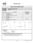
DESCRIPTION: Accent light Kit
APPLICATION: Maxima (2010)
PART NUMBER: 999F3 AW000 - Universal Accent Lighting Kit.
4.
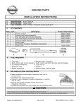
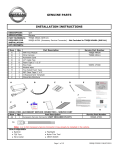
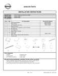
KIT CONTENTS:
Item
A
B
C
D
E
F
G
5.
QTY
1
1
1
1
1
1
Control module
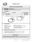
Encoder and harness assembly
Foot well lights and harness assembly
Cup holder lights and harness assembly
Harness Vehicle interface
Control Knob
Kit contents in back of Installation Instructions
Service Part Number
999F3 AW004
999F3 AW006
999F3 AW001
999F3 AW003
999F3 AW005
999F3 AW002
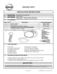
TOOLS REQUIRED
●
●
●
●
●
6.
Description
● Ratchet and 6" extension
Trim stick
8mm, 10mm and 11mm sockets ● 5/16", 3/16" and 9/32" drill bits, drill, drill stops.
● T-20 Torx bit
#2 Phillips screwdriver
● Scissors
Protective cloth
● Electrical tape, masking tape.
Needle nose plyers
● Grab-it tool (optional)
PRE-INSTALLATION CAUTION/NOTES
●
●
●
●
Dealer installation recommended. Instructions may refer to Service Manual
Installation may require special tools
This part is to be installed at a surface temperature no warmer than 65-100ºF
Remove and prepare templates located at the end of Installation Instructions
CAUTION
● This accessory must only be installed as specified in these instructions.
● Ensure at all times that parts are securely fitted and will not compromise the safe function of vehicle systems.
Riegner and Associates
Page 1 of 31
999F3 MW010II Rev. 07-14-2014
INSTALLATION INSTRUCTIONS - Accent lighting Kit
7. INSTALLATION OVERVIEW
8. CRITICAL STEPS
The following steps are critical and must be performed EXACTLY as specified to ensure
proper installation:
- Location of the lights must be followed exactly as described in this instruction.
- Posi-Tap™ instructions must be specifically followed as described.
Riegner and Associates
Page 2 of 31
999F3 MW010II Rev. 07-14-2014
INSTALLATION INSTRUCTIONS - Accent Lighting Kit
9. VEHICLE PREPARATION
1) Vehicle Preparation
a) Record customer radio presets.
b) Apply parking brake.
c) Turn off the ignition.
NOTE: USE CAUTION WHEN REMOVING / RE-INSTALLING TRIM COMPONENTS TO AVOID
DAMAGE, SCRATCHES, BREAKING OF CLIPS AND / OR INTERIOR TRIM PANELS.
MOVE ALL TRIM COMPONENTS TO A PROTECTED AREA.
WARNING
The battery is left connected as various parts of the car need to be
moved to enable components to be removed and replaced. Use caution
when activating parts of the car.
10.
ORDER OF INSTALLATION
a.
b.
c.
d.
e.
f.
g.
h.
i.
j.
Interior preparation - remove panels.
Install - Cup Holder installation.
Install - Encoder.
Reinstall - Center Console.
Install - Passenger Footwell light.
Reinstall - Glove Box and Footwell trim.
Install - Vehicle interface.
Install - Driver Footwell light.
System check.
Reinstall - Remaining Panels.
Riegner and Associates
Page 3 of 31
999F3 MW010II Rev. 07-14-2014
INSTALLATION INSTRUCTIONS - Accent Lighting Kit
11.
INTERIOR PREPARATION
Riegner and Associates
Fig. 1
1. Carefully remove the LH Instrument side
mask by the driver's door.
Fig. 2
2. Pull the fuse cover from the steering finisher.
Fig. 3
3. Remove the black #2 phillips screw in
the left side of the fuse cavity.
Page 4 of 31
999F3 MW010II Rev. 07-14-2014
INSTALLATION INSTRUCTIONS - Accent Lighting Kit
11.
INTERIOR PREPARATION
Fig. 4
Fig. 5
4. Carefully pull the steering finisher away
from the instrument panel.
5. Remove one (1) silver #2 phillips screw
holding the DDL (diagnostic Port) to the
panel.
Note: Place your hand behind the panel
to hold it as it is unscrewed.
Fig. 6
Riegner and Associates
6. Remove five (5) silver #2 phillips screws
holding the switch assembly to the
steering finisher.
Page 5 of 31
999F3 MW010II Rev. 07-14-2014
INSTALLATION INSTRUCTIONS - Accent Lighting Kit
11.
INTERIOR PREPARATION
Fig. 7
7. Disconnect A/C vent tube and electrical
connector from right side of panel.
Fig. 8
8. Disconnect courtesy light and two (2)
harness retaining clips from center of
panel.
Note: Remove the courtesy light bulb from
socket at this time. Bulb will not
be re-used.
Place all screws in a location where
they can be found later.
Fig. 9
Riegner and Associates
9. Remove the steering finisher and set aside.
Page 6 of 31
999F3 MW010II Rev. 07-14-2014
INSTALLATION INSTRUCTIONS - Accent Lighting Kit
11.
INTERIOR PREPARATION
Riegner and Associates
Fig. 10
10. Use a pry tool to remove the bottom
finisher from the shift knob and remove
the retaining clip.
Fig. 11
11. Depress the shift knob button and pull
the knob up. Set shift knob aside.
Fig. 12
12. Remove shifter display and trim.
Disconnect the display electrical connection.
Page 7 of 31
999F3 MW010II Rev. 07-14-2014
INSTALLATION INSTRUCTIONS - Accent Lighting Kit
11.
INTERIOR PREPARATION
Fig. 13
Fig. 14a
13. Remove three (3) #2 phillips screws,
from center console shifter assembly.
14. Carefully pry out both center footwell
panels from the driver and passenger
side center stack.
Fig. 14b
Riegner and Associates
Page 8 of 31
999F3 MW010II Rev. 07-14-2014
INSTALLATION INSTRUCTIONS - Accent Lighting Kit
11.
INTERIOR PREPARATION
Fig. 15
15. Disconnect the three (3) connectors
behind the passenger footwell panel,
under the center stack.
NOTE: Slide both seats all the way forward
at this time.
Fig. 16
16. Remove two (2) #2 phillips screws at
the rear of the center console.
NOTE: Turn ignition to "ON" position. Press on brake and pull shifter back to "D" position.
Turn ignition off.
Fig. 17
17. Carefully remove the center console
by grabbing the front and rear of the
assembly. Lift at the rear and pull back
slowly. Once the front of the console
is clear of the center stack, lift slowly
to clear the parking brake and shifter.
NOTE: Be careful not to damage the
headliner during removal.
Riegner and Associates
Page 9 of 31
999F3 MW010II Rev. 07-14-2014
INSTALLATION INSTRUCTIONS - Accent Lighting Kit
11.
INTERIOR PREPARATION
Fig. 18a
Fig. 18b
Fig. 19
18. Remove eight (8) #2 phillips
screws from the glove box
as shown.
NOTE: Remove the courtesy
light bulb from cross bar
socket at this time. Bulb
will not be re-used.
19. Carefully pull glovebox assembly out from
the dash and rest it on top of your legs.
Disconnect glovebox light and electrical
connector.
NOTE: Set the glovebox assembly aside.
Riegner and Associates
Page 10 of 31
999F3 MW010II Rev. 07-14-2014
INSTALLATION INSTRUCTIONS - Accent Lighting Kit
12.
INSTALLATION
Fig. 20
20. Place center console assembly upside down on work surface. Be carefull not to scratch the surface.
Use pry tool to carefully remove two (2) wire harness clips. Move harness aside.
Fig. 21
21. Remove four (4) #2 Phillips screws holding
the cup holder box to the center console.
NOTE: Place the screws in a secure place
for re-use.
NOTE: Print all templates at actual size.
Fig. 22
22. Apply template "A" and "B" on the side
of the cup holder as shown. The template
should be positioned with the letter "A"
or "B" in the upper left hand corner.
Drill two (2) 9/32 inch holes at the
locations indicated on the template.
Remove templates.
Install two (2) LED lenses through the
holes with the black retaining collar on
top of the cavity.
Riegner and Associates
Page 11 of 31
999F3 MW010II Rev. 07-14-2014
INSTALLATION INSTRUCTIONS - Accent Lighting Kit
12.
INSTALLATION
Fig. 23
23. Clean the light stick mounting area with
alcohol. Remove the pull tabs over the
tape on the end cup holder light stick.
Place the light stick over the black lens
retainer as shown.
Remove the pull taps over the tape of
the second cup holder light stick
(the one with wires at each end) and
place the light stick over the black lens
retainer as shown.
Fig. 24
24. Remove four (4) #2 Phillips screws from
storage bin. Carefully rotate the storage
bin up and out of the way allow access
to the armrest compartment.
NOTE: Place the screws in a secure place
for re-use.
Fig. 25
25. Apply template "C" to the armrest compartment
as shown. The template should be positioned
with the letter "C" in the lower right hand corner.
Using a 5/16" drill, carefully drill a hole for
the encoder.
Riegner and Associates
Page 12 of 31
999F3 MW010II Rev. 07-14-2014
INSTALLATION INSTRUCTIONS - Accent Lighting Kit
12.
INSTALLATION
Fig. 26
26. Install the encoder so that the shaft is
inside the rear storage area of the
armrest compartment.
Use 11mm nut to secure the encoder.
Install control knob over shaft of encoder.
NOTE: Be careful NOT to over tighten the
encoder nut.
Riegner and Associates
Fig. 27
27. Reinstall the storage bin using four (4)
#2 phillips screws.
Fig. 28
28. Reinstall the cup holder box using four (4)
#2 phillips screws.
Page 13 of 31
999F3 MW010II Rev. 07-14-2014
INSTALLATION INSTRUCTIONS - Accent Lighting Kit
12.
INSTALLATION
Fig. 29
29. Prepare the center console to be reinstalled into the vehicle. Dress the wires along the
existing harness with 4 inch cable ties. Use two (2) 11" cable ties at cup holder light loop.
Ideal cable tie spacing is 100mm to 120mm. Provide a 100mm service loop at the end
entering the area under the center stack.
NOTE: Trim all cable ties before you continue. Make sure cables do not invade shift cavity.
Shifter should still be in "D" position.
Fig. 30
30. Carefully load the modified center
console into the car. Position the
console over the parking brake and
shifter by gently moving the console
forward as it is lowered. Once the
console has cleared the parking brake
and shifter, pull back and align the two
pins over the shift console. If the
pins are aligned, the three retaining
screw holes will be in alignment.
Set the console over the two rear
retaining screw locations.
NOTE: Be careful not to damage the
headliner during reinstallation
of the center console.
13-16 N-m
Riegner and Associates
Page 14 of 31
999F3 MW010II Rev. 07-14-2014
INSTALLATION INSTRUCTIONS - Accent Lighting Kit
13.
REINSTALLATION - CENTER CONSOLE
Fig. 31
NOTE: The shifter should be moved back
into the "P" position.
31. Once aligned, install three (3) #2 phillips
screws securing the center console to the
shifter assembly.
Fig. 32
NOTE: Slide both seats all the way forward
at this time.
32. Install two (2) #2 phillips screws at the
rear of the console securing the center
console to the vehicle.
Fig. 33
33. Reconnect the display electrical connector
and then reinstall the shifter display trim.
13-16 N-m
Riegner and Associates
Page 15 of 31
999F3 MW010II Rev. 07-14-2014
INSTALLATION INSTRUCTIONS - Accent Lighting Kit
13.
REINSTALLATION - CENTER CONSOLE
Fig. 34
34. Reinstall the shift knob.
Fig. 35
35. Reinstall the retaining clip and collar.
NOTE: Be sure the shift collar is replaced
facing in the right direction.
Fig. 36
NOTE: Attach one (1) 58mm x 82mm
foam tape to the underside of the
accessory control module, covering
the screw in the center.
36. Place one (1) piece of foam tape over
the top of the accessory controller.
It should be on the opposite side of the
sticky foam tape covering the screw.
13-16 N-m
NOTE: Do NOT pull cover off tape on
controller at this time.
Riegner and Associates
Page 16 of 31
999F3 MW010II Rev. 07-14-2014
INSTALLATION INSTRUCTIONS - Accent Lighting Kit
15.
INSTALLATION
COMPLETELY READ STEPS 37-40 BEFORE INSTALLING BRACKETS.
Fig. 37
37. Prepare to mark drill locations at the glovebox opening. Measure and mark in from
the back rib, 2mm to 3mm. Mark a line 2mm to 3mm in from the edge of the slot on the
left side as shown. Mark a line even with the right edge of the glovebox opening as shown.
NOTE: Brackets will fit into the outermost openings outside the honeycomb structure behind
the support rail. Feel behind the crossbar to be sure of hole positioning before drilling.
38. Carefully drill a 3/16 inch hole at both locations.
NOTE: Do NOT drill past the bottom rib. Use a drill stop set to 4mm.
39. Attach two (2) U Nuts to the small 30mm X 15mm
"L" bracket at the long end.
Fig. 39
Riegner and Associates
Page 17 of 31
999F3 MW010II Rev. 07-14-2014
INSTALLATION INSTRUCTIONS - Accent Lighting Kit
15.
INSTALLATION
Fig. 40
13-16 N-m
40. Securely attach the two (2) "L" brackets with U nuts to the glovebox support rail
with two (2) #2 phillips screws.
Both brackets shown from behind support rail, installed and ready for passenger side light stick.
NOTE: Both brackets should be securely fastened to the support rail.
Riegner and Associates
Page 18 of 31
999F3 MW010II Rev. 07-14-2014
INSTALLATION INSTRUCTIONS - Accent Lighting Kit
15.
INSTALLATION
Cable Loop
.5
11.5
Clean here
41. Prepare the passenger side light stick. Clean the LED areas with alcohol wipe.
Fix a 12.5mm X 19mm X .7mm piece of double sided foam tape at
locations .5 to end of the stick AND at location 11.5 to the other end.
8
4
Clean here
42. Prepare the driver's side light stick. Clean the Non-LED side with alcohol wipe.
Fix a 12.5mm X 102mm X .7mm piece of double sided foam tape from
locations 8 to the end of the stick AND from location 4 to the other end.
Fig. 43
43. Push the drivers light stick through the
center stack to the drivers side footwell.
NOTE: The driver's side light stick should
be left in the driver's footwell for
later installation.
Riegner and Associates
Page 19 of 31
999F3 MW010II Rev. 07-14-2014
INSTALLATION INSTRUCTIONS - Accent Lighting Kit
15.
INSTALLATION
Fig. 44
44. Pull the tape covers from the two (2)
pieces of foam tape attached to the
passenger light stick. Place the light stick
over the "L" brackets with the LEDs
pointing down such that the tape rests
on the 'L' bracket. Secure each location
with two (2) 4 inch cable ties. Be sure
to turn cable ties upward away from
footwell.
As an optional step, you can secure the
cable with a cable tie at the center of the
light stick. Do NOT block LEDs.
NOTE: The cable should be behind the back
of the "L" bracket as shown.
Riegner and Associates
Fig. 45
45. Reconnect glovebox light and electrical
connector. Reinstall the glovebox
assembly.
Fig. 46
46. Route accessory harnesses under the
center stack. Plug the accessory harnesses
into the control module and allow to sit
under center stack.
Page 20 of 31
999F3 MW010II Rev. 07-14-2014
INSTALLATION INSTRUCTIONS - Accent Lighting Kit
16.
POSI TAP INSTRUCTIONS
Fig. 1
b)
a)
1) Tap vehicle wire.
a) Remove cap (slot side) from tap body.
b) Slide cap around vehicle wire.
c) Tighten the tap TIGHT with finger
pressure.
NOTE: Do not re-use the tap for subsequent
re-installation. Figures are not to scale
Fig. 2
2) Inspect the tap to ensure correct installation.
NOTE: Avoid putting pressure on the vehicle
wire and tap for the remainder of the
installation.
i. Straight and evenly spaced all the way around
ii. Tight and minimize gap (wire jacket should
be crushed)
Fig. 3
e) Insert wire to here
c)
a)
d)
f) Tighten
Fig. 4
3) Inspect the tap to ensure correct installation.
a) Remove tap (non-pierce) side from tap.
b) Remove the protective stub from the wire.
c) Insert wire through the non-pierce side
opening.
d) Spread the individual strands into fan
shape.
e) Insert wire into the tap body and ensure
that it is all the way in.
f) Tighten the tap TIGHT with finger
pressure.
4) Confirm the tapped accessory wire.
a) Inspect the tap to ensure correct
installation.
b) Test the signal to ensure that it is
working properly.
i. Straight and evenly spaced all around
ii. Tight and no gap and test the signal
Riegner and Associates
Page 21 of 31
999F3 MW010II Rev. 07-14-2014
INSTALLATION INSTRUCTIONS - Accent Lighting Kit
16.
Posi Tap Instruction
Fig. 5
Vehicle Harness
...
b)
17.
a)
5) Secure the tap.
a) Secure the tapped wire on the non-pierce
side to the body of the tap with electrical
tape (≥ 2 revolutions).
b) Secure the body to harness where vehicle
wire is being tapped with electrical tape
(≥ 2 revolutions).
Accessory
INSTALLATION
CAUTION
●
●
Color(s) given in illustration(s) are for reference only. Use location(s) where color deviates.
If a vehicle wire is being used by another accessory and a posi-Tap is present, tap
the accessory wire NOT the vehicle wire.
Fig. 47
47. Carefully loosen the Instrument Cluster
trim panel by removing the two (2) black
Philips screws at the lower left and right
corners.
Pull the panel towards the driver's seat
and free from the Instrument panel.
NOTE: Do NOT disconnect the switches.
Rotate the panel to the right,
out of the way.
Fig. 48
48. Remove the three (3) #2 Philips screws
that retain the Instrument Cluster.
One on top and one at the left and right
lower corners.
Do Not disconnect the Cluster. Rotate the
assembly to the right and up out out of
the way.
NOTE: Disconnect a white electrical
connector on the left side of the
cluster if necessary to allow the
assembly to rotate.
Riegner and Associates
Page 22 of 31
999F3 MW010II Rev. 07-14-2014
INSTALLATION INSTRUCTIONS - Accent Lighting Kit
17.
INSTALLATION
Fig. 49
49. The BCM is the box at the back of the cavity
with two (2) screws retaining it to the IP
frame.
Note: There may be special one-way screws
used to secure the BCM to the vehicle.
Use a 'Grab-it' or other tool to remove
the special screws.
50. Remove the fasteners that hold the BCM
in place.
Fig. 51
51. Pull the BCM forward and carefully turn it
over. Notice the connector to the left.
52. Identify the Yellow wire at the corner of
the connector as shown in the picture.
This wire is the room lamp circuit, LG02.
Fig. 52
Riegner and Associates
Page 23 of 31
999F3 MW010II Rev. 07-14-2014
INSTALLATION INSTRUCTIONS - Accent Lighting Kit
17.
INSTALLATION
Fig. 53
53. Use a large cable tie to guide the Brown
Accessory wire to the cavity where the
BCM is housed.
`
Fig. 54
54. Connect the Brown accessory wire from the
controller to the Yellow wire at the BCM
connector using a Posi-Tap.
55. Reinstall the BCM.
Yellow
Riegner and Associates
Brown
56. Reinstall the Instrument cluster and the
Instrument cluster trim.
Page 24 of 31
999F3 MW010II Rev. 07-14-2014
INSTALLATION INSTRUCTIONS - Accent Lighting Kit
17.
INSTALLATION
NOTE: There are four wires in the power harness for this kit. They are:
Brown - Room Lamp Circuit
Black - Ground
Green - B+ (battery)
Blue - Accessory
Fig. 57
57. Locate the Fuse Block and identify the
following two wires.
AA26 is a Yellow/Red wire.
White with a blue stripe
HA02 is a Violet/Yellow wire.
Violet with a yellow stripe.
NOTE: Each wire is in a separate connector.
Yellow/Red wire connector has 10 Pins
Violet Yellow wire connector has 12 Pins
58. Locate the Yellow/Red wire between Red/Blue
wire and Blue wire.
Use a posi-tap and connect the Green
Accessory wire to the Yellow/Red vehicle
wire by the fuse block.
Consult the Mechanization if needed.
59. Locate the Violet/Yellow wire. It would be
across from the Red/Blue wire.
Use a posi-tap and connect the Blue
Accessory wire to the Violet/Yellow vehicle
wire by the fuse block.
Consult the Mechanization if needed.
Page 25
999F3 MW010II Rev. 07-14-2014
INSTALLATION INSTRUCTIONS - Accent Lighting Kit
17.
INSTALLATION
60. Use an 8mm nut driver or equivalent to remove
one of the two bolts just under the fuse
panel. Place the bolt through the eyelet on
the Black Accessory wire and back into the hole.
Tighten bolt.
NOTE: If other accessories share thre 8mm ground bolt,
eyelets should be spaced 30 degrees apart.
NOTE: All controller wires should be connected.
OVER ALL - this is how the controller needs to be connected:
a. Brown from controller goes to LG02; a Yellow wire at the BCM.
b. Blue from controller goes to HA02, a Violet/Yellow wire above the fuses.
c. Green from controller goes to MA02 a White/Blue wire above the fuses.
d. Black from controller goes to ground; a small bolt to the lower right of the fuse block.
Riegner and Associates
Page 26 of 31
999F3 MW010II Rev. 07-14-2014
INSTALLATION INSTRUCTIONS - Accent Lighting Kit
17.
INSTALLATION
Fig. 61
61. Peel the cover of the tape on the
controller and place the controller on
the carpet under the center stack.
Loosely route power harness towards
controller.
Fig. 62
62. Bundle and dress the excess cables from
the encoder and forward cavity lights and
secure with cable ties as shown. Use two
(2) pieces of foam tape to hold the cables
to the HVAC unit as shown.
Note: Be sure cables do not touch footwell
panel, to prevent rattling.
Fig. 63
Riegner and Associates
63. Reinstall the passenger footwell panel
at the center stack.
Page 27 of 31
999F3 MW010II Rev. 07-14-2014
INSTALLATION INSTRUCTIONS - Accent Lighting Kit
17.
INSTALLATION
Fig. 64a
64. Use cable ties to secure the power
harness for the accessory under the
Instrument panel.
Fig. 64b
Note: Trim all cable ties. Plug the power harness into the controller. Verify four (4) cables
are plugged into the controller.
Fig. 65
65. Bundle the excess wire at the fuse block
as shown.
Note: Excess wiring MUST NOT block fuses.
Pull all excess wiring up and clear of
fuses. Use a larger cable tie if
necessary.
Riegner and Associates
Page 28 of 31
999F3 MW010II Rev. 07-14-2014
INSTALLATION INSTRUCTIONS - Accent Lighting Kit
17.
INSTALLATION
Fig. 66
66. Secure excess wire with foam tape and
cable ties.
Reinstall driver's footwell panel.
Prepare To Install Driver's Side Light Stick.
67. Using a metric scale or ruler, measure and mark 25mm from the bottom edge.
Mark a line that matches up with the right edge of the DDL opening.
Measure and mark 60mm from the right edge and 20mm from the bottom edge.
Use a 3/16 inch drill and drill both locations.
Fig. 67
Riegner and Associates
Page 29 of 31
999F3 MW010II Rev. 07-14-2014
INSTALLATION INSTRUCTIONS - Accent Lighting Kit
17.
INSTALLATION
68. Work on the steering finisher in the driver's floor area. Clean mounting area with alcohol
wipe. Peel tabs away from the adhesive tape. Place the light stick so that the left hole is
aligned with the 10.5 location and the right hole is aligned with the 1 location on the stick.
Fig. 68
69. Place a cable tie through both holes and tighten around the light stick to secure it to the
panel. Trim the cable ties and turn them inwards so the clipped end is on the inside of
the panel.
70. Reinstall the steering finisher, fuse cover and side mask.
Note: Trim all cable ties. Check installation. Check and clear any trouble codes.
Riegner and Associates
Page 30 of 31
999F3 MW010II Rev. 07-14-2014
INSTALLATION INSTRUCTIONS - Accent Lighting Kit
18.
CHECK OUT
(1) Open the rear storage area of the center console.
(2) Turn the vehicle ignition switch to the "ACC" position, push the lighting control knob and
confrm the Accent Lighting illuminates.
(3) Turn the lighting control knob and confirm that the color changes through 20 variations.
(4) Press and hold the control knob for 3 seconds and confirm that the Accent Lighting
enters the "Demo Mode" and cycles through colors. Press knob again to exit demo mode.
(5) Leaving the accessory ON, turn the Interior Room Lamp to "DOOR" and ignition switch
OFF. Open the door and confirm the Accent Lighting illuminates.
(6) Leaving the accessory ON, and the ignition switch OFF, close and lock the door using
CDL or Key Fob (if equipped). Confirm that the Accent Lighting turns off.
(7) Reset the radio presets to the recored settings.
(8) Place the Accent Lighting Quick Reference card in the glovebox.
(9) Check the trim for a proper, flush fit after re-installing the interior components.
(10) Clean the interior of the vehicle.
(11) Inspect the vehicle interior and exterior for damage.
(12) Check and clear trouble codes ( DTC ).
Riegner and Associates
Page 31 of 31
999F3 MW010II Rev. 07-14-2014
INSTALLATION INSTRUCTIONS - Accent Lighting Kit
19.
BILL OF MATERIALS
Nissan Universal Accent Lighting Kit - 999F3 AW000
Parts Contained in Bag Labelled 'Installation Kit'.
1 Cable tie 15" - Black
Qty
Part Number
4
2 Cable tie 11" - Black
2
3 Cable tie 4" - Black
13
4 Grey foam rectangle 80mm x 30mm x 5mm - Adhesive one side
6
5 Small bracket 28mm long
2
6 Medium bracket 54mm long
1
7 Large bracket 80mm long
1
8 Posi-tap connector - Red / Grey
3
999M1 VT000
9 Control knob (Black + white printing)
1
999F3 AW002
10 Alcohol preparation wipe
4
11 U' Nut
2
12 Module adhesive fixing 53mm x 74mm
1
13 Lens Retaining Ring 9mm OD - Black
2
14 Clear plastic lens - 7.5mm diameter
2
15 Pozi-drive self-tap screw 1/2" long - Black
2
16 Encoder lock nut
1
17 Quick reference guide
1
18 Double-sided adhesive fixing 12mm x 20mm (All on one backing paper)
4
19 Double-sided adhesive fixing 12mm x 102mm (All on one backing paper)
4
20 Parts list / Replacement template
21 Vehicle interface harness
1
999V2 AW000
1
999F3 AW005
22 Encoder and harness assembly
1
999F3 AW006
23 Cup-holder lights and harness assembly
1
999F3 AW003
24 Foot-well lights and harness assembly
25 Control module (within polythene zip bag)
1
999F3 AW001
1
999F3 AW004
999F3 AW007
Parts Not In 'Installation Kit' bag.
Riegner and Associates
BOM
999F3 MW010II Rev. 07-14-2014
INSTALLATION INSTRUCTIONS - Accent Lighting Kit
Maxima Mechanization
Riegner and Associates
Mechanization
999F3 MW010II Rev. 07-14-2014
INSTALLATION INSTRUCTIONS - Accent Lighting Kit
Templates must be
printed to scale
Riegner and Associates
10mm
L42A
CUP HOLDER
TEMPLATE
Template A
1 inch
999F3 MW010II Rev. 07-14-2014
INSTALLATION INSTRUCTIONS - Accent Lighting Kit
Templates must be
printed to scale
Riegner and Associates
10mm
L42A
CUP HOLDER
TEMPLATE
Template B
1 inch
999F3 MW010II Rev. 07-14-2014
INSTALLATION INSTRUCTIONS - Accent Lighting Kit
Templates must be
printed to scale
Riegner and Associates
10mm
L42A
ENCODER
TEMPLATE
Template B
1 inch
999F3 MW010II Rev. 07-14-2014