1
GENUINE PARTS
INSTALLATION INSTRUCTIONS
1.
2.
3.
DESCRIPTION: Trailer Hitch Harness Kit
APPLICATION: Infiniti JX
PART NUMBER: 999T8 YZ000- Trailer Hitch Harness Kit
4.
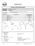
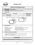
KIT CONTENTS:
Item
A
B
C
QTY
Description
1
Exterior 7-Pin Connector Harness
1
Relay Box and Harness
1
Misc. parts kit
Service Part Number
24340 3KA0A
24168 3JA0A
B
A
5.
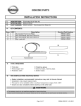
TOOLS REQUIRED
Ɣ Trim stick
Ɣ 10mm socket
Ɣ Ratchet with 2" and 12" extension
6.
ł Work gloves
ł Long needle nose pliers
ł Air ratchet
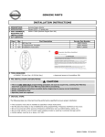
PRE-INSTALLATION CAUTION/NOTES
Ɣ
Ɣ
Ɣ
Ɣ
Dealer installation recommended. Instructions may refer to Service Manual
Installation may require special tools
This part is to be installed at a surface temperature no warmer than 65-100ºF
Remove and prepare templates located at the end of Installation Instructions
CAUTION
ł This accessory must only be installed as specified in these instructions.
ł Ensure at all times that parts are securely fitted and will not compromise the safe function of vehicle systems.
Page 1 of 12
999T8 YZ000 II 12-20-2011
INSTALLATION INSTRUCTIONS - Trailer Harness Kit
7.
INSTALLATION OVERVIEW
8. CRITICAL STEPS
The following steps are critical and must be performed EXACTLY as specified to ensure
proper installation:
- Location of the harness must be followed exactly as described in this instruction.
- Test the functionality of the kit before final clean up and reinstallation of interior panels.
Page 2 of 12
999T8 YZ000 II 12-20-2011
INSTALLATION INSTRUCTIONS - Trailer Harness Kit
9.
VEHICLE PREPARATION:
1)
2)
Apply parking brake
Confirm the vehicle is no longer in the default shipping state (Extended Storage Switch Pulled Up and BCM
in Transit Mode). Failure to confirm the vehicle has been removed from this state will result in the loss of
normal vehicle operation. The confirmation requires two checks:
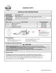
2a) Locate the Extended Storage Switch
2b) Turn the ignition switch from "OFF" to "ON" position. If
in the cabin fuse block. Once located,
turn indicators illuminate for approx. 1 minute, the
check that it is in the "Customer"
vehicle is in shipping mode. To exit shipping mode,
position. See below for reference.
return the ignition switch to "OFF" position.
Simultaneously push the wiper and turn signal stalks
downward and hold for 2 seconds.
INVENTORY - UP
CUSTOMER - DOWN
NOTE: Typical vehicle
condition shown here.
Switch is easily identifiable
by the permanent, pushpull fuse holder.
Actual position on the fuse
block may vary, vehicle to
vehicle.
3) Record customer
radio presets.
NOTE: USE CAUTION WHEN REMOVING / RE-INSTALLING TRIM COMPONENTS TO AVOID
DAMAGE, SCRATCHES, BREAKING OF CLIPS AND / OR INTERIOR TRIM PANELS.
MOVE ALL TRIM COMPONENTS TO A PROTECTED AREA.
WARNING
Disconnect negative battery terminal before
proceeding.
10.
Order of Installation
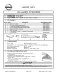
1. Remove panels and trim.
2. Install Harness
3. Connect Wiring
4. Replace all panels
Page 3 of 12
999T8 YZ000 II 12-20-2011
INSTALLATION INSTRUCTIONS - Trailer Harness Kit
11.
INTERIOR PREPARATION
Fig. 1
1. Open rear hatch.
Fig. 2
2. Open the rear cargo floor panel.
Carefully pull up the bottom portion of
the hatch door welt strip.
Fig. 3
3. Carefully pry off the small trim panel from
inside the striker loop at the center of the
rear kick plate.
Page 4 of 12
999T8 YZ000 II 12-20-2011
INSTALLATION INSTRUCTIONS - Trailer Harness Kit
11.
INTERIOR PREPARATION
Fig. 4
4. Pry off the rear kick plate along the bottom
of the hatch opening.
NOTE: There are six (6) clips around the
edge of the trim panel. Pry off leading
edge first for easier removal.
Fig. 5
REMOVAL OF OPTIONAL SUBWOOFER
If vehicle is not equipped with subwoofer,
proceed to step 8.
5. Unscrew the large retaining bolt from the
top of the subwoofer assembly.
Fig. 6
6. Carefully lift the subwoofer assembly out
of the storage compartment. Disconnect
the electrical plug.
Page 5 of 12
999T8 YZ000 II 12-20-2011
INSTALLATION INSTRUCTIONS - Trailer Harness Kit
11.
INTERIOR PREPARATION
Fig. 7
7. Remove the Subwoofer assembly and
set aside.
Fig. 8
8. Remove three (3) 10mm bolts from the
storage compartment unit.
Fig. 9
9. Fold down rear seat. Lift the storage
compartment assembly up and over so
it rests on the rear seat backs as shown.
Page 6 of 12
999T8 YZ000 II 12-20-2011
INSTALLATION INSTRUCTIONS - Trailer Harness Kit
11.
INTERIOR PREPARATION
Fig. 10
10. Locate the two cargo loops on the
driver side trim panel. Carefully pry
up the access panels in the center
of the loops.
Fig. 11
11. Remove two (2) 10mm bolts from the
cargo loop assemblies. Remove the
cargo loop assemblies and set aside.
Remove two (2) press fasteners from
inside edge of panel.
Fig. 12
12. Remove the carpeted trim panel
and set aside.
Page 7 of 12
999T8 YZ000 II 12-20-2011
INSTALLATION INSTRUCTIONS - Trailer Harness Kit
12.
INSTALLATION
Fig. 13
13. Locate the bracket along the inside
rear of the driver side compartment.
NOTE: Work gloves are recommended for
steps 13 through 18 due to sharp
metal edges on the surrounding
bracket.
Fig. 14
14. Fit the new relay box mounting bracket
into position as shown. Secure with
two (2) 10mm bolts.
NOTE: An air rachet with a 2" extension
will help with this installation step.
15. Install three (3) relays into relay box.
Fig. 16
16. Move the Relay Box and harness into
position near the mounting bracket.
Insert the two connectors from the Relay
Box into the existing vehicle connectors
above the mounting bracket.
Page 8 of 12
999T8 YZ000 II 12-20-2011
INSTALLATION INSTRUCTIONS - Trailer Harness Kit
12.
INSTALLATION
Fig. 17
17. Due to the tight spacing inside the bracket
area, the relay box assembly should be
installed as follows:
1) Rotate the assembly in a clockwise
direction to help move the assembly
into position near the bracket.
2) Rotate the assembly back in a
counter-clockwise direction before
final mounting.
Fig. 18
18. Snap the Relay Box into position on the
mounting bracket as shown.
Fig. 19
19. Use one (1) 17" cable tie to secure the
two harness relays to the inside of the
storage area bracket.
NOTE: Be sure to cut away the excess cable
tie strap.
Page 9 of 12
999T8 YZ000 II 12-20-2011
INSTALLATION INSTRUCTIONS - Trailer Harness Kit
12.
INSTALLATION
Fig. 20
20. Reinstall the carpeted trim panel and
both cargo loops.
21. Reinstall the storage compartment unit.
22. Reinstall optional Subwoofer Assembly
if necessary (see Fig. 5 & 6).
23. Reinstall the rear hatch Kick Plate and
small trim panel (see Fig 3 & 4).
24. Reinstall the hatch door welt strip (see Fig.2)
NOTE: It is recommended that the vehicle be raised on a hoist at this time.
Fig. 25
25. Locate the factory trailer harness connectors
located underneath the rear passenger
corner of vehicle. Remove the sealer plugs
from the connectors and discard.
NOTE: Use long nose pliers or vice-grips
to release the sealer plug clips
Fig. 26
26. Install the two (2) connectors on the
accessory harness to the two (2)
connectors on the factory harness.
Page 10 of 12
999T8 YZ000 II 12-20-2011
INSTALLATION INSTRUCTIONS - Trailer Harness Kit
12.
INSTALLATION
Fig. 27
27. Route the accessory harness along the
hitch and attach one (1) clip to the hole
in factory bracket as shown.
NOTE: Hitch assembly must be installed
on vehicle before proceeding.
Fig. 28
28. From the outside of the rear bumper,
align the seven pin standard barrel
connector key ways to match the hole
provided in hitch. Rotate the connector
90 degrees to lock into position.
Fig. 29
29. From the inside of the rear bumper,
connect the seven pin mating connector
on the connector harness to the back of
the seven pin standard barrel connector.
Page 11 of 12
999T8 YZ000 II 12-20-2011
INSTALLATION INSTRUCTIONS - Trailer Harness Kit
13.
CHECK OUT
(1) Inspect the vehicle for
unfinished work.
(2) Reconnect battery.
(3) Utilizing a volt meter, confirm the voltage
is at or near zero DC volts when checking
between 'GROUND' pin on the 7 Pin Tow
Connector (See Mechanization if necessary) and
an unpainted and clean area of the vehicle's body.
SAFETY NOTE - THE REMAINDER OF THIS
CHECK-OUT REQUIRES TWO INDIVIDUALS
TO COMPLETE FOR SAFETY PURPOSES.
(4) Confirm the vehicle's shifter is in the PARK position and place ignition switch into "ON" position.
The vehicle's engine does NOT need to be running for any of the following checks.
(5) Use a volt meter to confirm the voltage is at or near 12 DC volts when checking between 'GROUND' pin and '12V
POWER' pin on the 7 Pin Tow Connector (See Mechanization if necessary).
(6) Turn the light switch located on the steering column stalk to the PARK/TAIL LAMP position.
(7) Use a volt meter to confirm the voltage is at or near 12 DC volts when checking between 'GROUND' pin and
'PARKING LAMPS & LICENSE' pin on the 7 Pin Tow Connector (See Mechanization if necessary).
(8) Apply the brakes.
(9) Use a volt meter to confirm the voltage is at or near 12 DC volts when checking between 'GROUND' pin and the
'LEFT & RIGHT TURN/STOP' pins on the 7 Pin Tow Connector (See Mechanization if necessary).
(10) Release the brakes and turn hazard switch to "ON" position.
(11) Use a volt meter to confirm the voltage oscillates between zero and 12 DC volts depending on the state of the
vehicle lamps. This can be done by checking between 'GROUND' pin and the 'LEFT & RIGHT TURN/STOP' pins on the 7
Pin Tow Connector (See Mechanization if necessary).
(12) Set parking brake. Apply the brakes and shift the vehicle into the REVERSE position. Keep applying brakes during
the entire time the vehicle's shifter is in the REVERSE position and is being checked by the 2nd individual.
(13) Use a volt meter to confirm the voltage is at or near 12 DC volts when checking between 'GROUND' pin and the
'REVERSE' pin on the 7 Pin Tow Connector (See Mechanization if necessary).
(14) Return the vehicle's shifter position to PARK. After confirming the shifter is in PARK position, the brake pedal can
be released. The parking brake can also be released.
NOTE - CHECK-OUT STEPS 3 THRU 13 ASSUMES A TRAILER IS NOT AVAILABLE FOR VISUALLY CHECKING
THE SYSTEM IS OPERATIONAL. IF A TRAILER IS AVAILABLE FOR CHECK-OUT, CONNECT THE TRAILER TO
THE 7 PIN TOW CONNECTOR AND COMPLETE STEPS 3 THRU 13 WITHOUT A VOLT METER BY SIMPLY
CHECKING THE LAMP STATES OF THE TRAILER. IF ANY OF THE TRAILER LAMPS FAIL TO ILLUMINATE, A
VOLT METER SHOULD BE USED AS EXPLAINED ABOVE TO VERIFY THE ACCESSORY WIRING IS OPERATING
CORRECTLY.
(15) If this vehicle will be returned to a dealer lot or showroom for an extended period of time, be sure the
extended storage switch is placed in the "inventory" position. (Refer to section 9 - Vehicle Preparation)
Page 12 of 12
999T8 YZ000 II 12-20-2011
INSTALLATION INSTRUCTIONS - Trailer Harness Kit
14.
BILL OF MATERIALS
Trailer Harness Kit - 999T8 YZ000
Parts Contained in Bag Labelled 'Installation Kit'.
Qty
Part Number
1 BRKT-CLIP
1
24239 3JA2A
2 TIE-STRAP (17 INCH)
1
24216 10Y80
3 SCREW- 10MM, HEX HEAD, 16MM LENGTH
2
85-66616-2A
4 EXTERIOR SUB-HARNESS (FOR ATTACHING 7 PIN TOW CONNECTOR)
1
24340 3KA0A
5 7 PIN TOW CONNECTOR (STANDARD BARREL TYPE)
1
24340 ZR10A
6 INTERIOR SUB-HARNESS W/RELAY BOX
1
24168 3JA0A
7 RELAY-1M (MANUAL INSTALLATION INTO RELAY BOX)
2
25230 79917
8 RELAY-2M (MANUAL INSTALLATION INTO RELAY BOX)
1
25230 7996A
9 COMMON PAPER - ACCESSORY WEBSITE ADDRESS
1
10 WEB INSTRUCTIONS
999V2 AW000
999T8 YZ000 II
BOM
999T8 YZ000 II 12-20-2011
INSTALLATION INSTRUCTIONS - Trailer Harness Kit
15.
MECHANIZATION
Mechanization
999T8 YZ000 II 12-20-2011