1
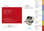
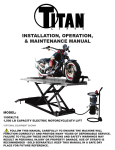
R-SERIES
SHOCK ABSORBER
INSTALLATION,
OPERATION, AND
SERVICE MANUAL
[email protected]
www.efdyn.com
7734 E. 11TH ST.
(800) 950-1172
TULSA, OK 74112
FAX (918) 835-3334
2
I.
General Instructions
The EFDYN R-Series Model shock absorbers are reliable units designed to
cushion a moving load to the most gentle stop possible. They are ruggedly built
and will perform for many years of trouble – free service provided adequate
maintenance procedures are followed.
A. Surface Finish
All standard shock absorbers are painted EFDYN Blue per EFDYN Spec.
1-3238-02-01. Shocks used in outdoor environments are painted with Anchor
Paint black epoxy #3900. THE PISTON ROD SHOULD NEVER BE PAINTED.
B. Serial Number
Every unit manufactured by EFDYN is assigned a serial number. It is
stamped on the unit. This number should always be given when ordering a unit for
an identical application or spare parts.
C. Fluid Filling
All self-contained (spring return, air charge return, and mechanical return)
shock absorbers are shipped filled with oil unless special conditions dictate
otherwise. Air return shock absorbers are shipped dry. (See Filling Instructions,
Section IV).
D. Spring Return
Spring return models incorporate internal or external springs, which return
the piston rod to the outward position with sufficient force to overcome friction. Do
not rely on the spring force to return outside members which might be part of the –
moving load.
E. Air Charged Shock Absorbers
Air charged shock absorbers are shipped filled with oil to proper level and
without air charge (piston rod in compressed position). Prior to usage unit must be
charged to air pressure specified.
II.
INSTALLATION
A. General
R-Series standard self-contained (spring return) shock absorbers may be
mounted horizontally or vertically with piston rod up. If a unit has been specified to
operate at an angle of more than five degrees either side of horizontal or vertical
centerline, bleeder screws will have not been relocated accordingly before
shipment. However, if an accumulator is used, a standard shock absorber may be
mounted at any angle.
B. Mounting Support
1. The supporting structure must be rigid and so constructed that deflection under full
stopping force is negligible.
Efdyn, Incorporated
th
7734 East 11 Street
Tulsa, Oklahoma 74112
www.efdyn.com
Toll Free: 800-950-11722
Phone: 918-838-1170
[email protected]
3
2. The moving load must be well guided and in line with the shock
absorber at point of impact. If it is subject to lateral wandering, side forces may be
imposed on the piston rod resulting in excessive bearing wear. If the contacting
surface on the load is soft in comparison to the cap, a depression may be formed
which could trap the bumper cap and result in a bent rod if the load shifts. To avoid
this, attach a hardened plate at the point of impact on the moving load.
C. Protecting Piston Rod
Trouble free performance depends largely on smooth functioning of the
piston rod. Utmost care should be taken during installation and operation to
prevent bending, denting, scratching or gouging.
D. Special Safety Measures
1. Mounting screws should be of high strength alloy steel.
2. External mechanical stops are recommended for the load, set to contact just
before the bumper cap on the piston rod strikes the shock absorber front head.
This added protection is desirable in order to prevent the bumper cap from
impinging against the front head.
3. Back up bar, keyed or welded to base, must be provided at rear of lug mounted
models to prevent shear loading on mounting bolts.
4. Run the load into the bumper at slow speed (after the shock absorber has been
mounted and filled) to test for proper operation.
III.
HYDRAULIC FLUIDS
Dexron®-III/ Mercon® Hydraulic Fluid
Typical specifications are:
Gravity API …………………………………………………31.0
Viscosity, Saybolt Universal Seconds
at 100 degrees F …………………………………..175
at 210 degrees F …………………………………..51
Viscosity, CP, Brookfield (CRC L-45)
At –40 degrees F ………………………………..17,500
Viscosity Index ASTM D-2270 …………………………….183
Flash, COC Degrees F ……………………………………..367
Pour Point, Degrees F (not less than) …………………….-60
Corrosion – ASTM D-665 ……………………………..…..Pass
Color ………………………………………………………….Red
Efdyn, Incorporated
th
7734 East 11 Street
Tulsa, Oklahoma 74112
www.efdyn.com
Toll Free: 800-950-11723
Phone: 918-838-1170
[email protected]
4
IV.
OIL FILLING
A. With shock absorber in a horizontal fill port up position, remove filler port plug.
B. Remove bleeder screw.
C. Pour oil into filler port until a steady flow of oil without air bubbles emerges from the
bleed screw hole. Let shock absorber oil level bleed down to the bleed screw hole.
D. Replace filler port plug and bleeder screw.
E. Force piston rod in slowly several times.
F. Remove port plug and bleed screw – recheck oil level, adding more if required. DO
NOT OVERFILL - This can cause distortion of the outer jacket tube during operation.
V.
OPERATION
A.
Uniform Deceleration
This principle governing the operation of EFDYN shock absorbers provides the
gentlest possible cushioning throughout the complete stopping range. The precision
non-adjustable orifices specifically engineered and designed for conditions of each
load range to ensure optimum performance.
1. Velocity
If the load to be stopped has no propelling force (such as gravity, air
cylinder, hydraulic or electric drive) then the stopping force results from
inertia only – velocity at impact does not affect uniform deceleration. Under
these conditions hydraulic pressure in the shock absorber will be
proportional to impact velocity which is limited to the maximum capacity
rating of the shock absorber.
2. Propelling Force
If any significant propelling force is present, any change in moving load
weight, velocity, or propelling force will adversely affect the stopping
characteristics of the shock absorber. For all practical purposes, a load
variation of 15% above or below the design load will not seriously alter the
uniform deceleration characteristics of the shock absorber.
B.
Operating Temperature
1. Range with Dexron®-III/ Mercon® Hydraulic Fluid ---- -40 to +190 F
2.
Temperature Rise: Hydraulic shock absorbers convert all the kinetic energy of
the moving load into heat during operation. This heat build-up causes a
temperature rise within the shock absorber which is proportional to the energy
absorbed, cycle rate, bore and stroke of the shock and ambient temperature.
Radiation from the sun or other hot bodies and contact area of mounting
members are factors to be considered.
Efdyn, Incorporated
th
7734 East 11 Street
Tulsa, Oklahoma 74112
www.efdyn.com
Toll Free: 800-950-11724
Phone: 918-838-1170
[email protected]
5
C.
VI.
Other factors Influencing Successful Operation
1.
Polyurethane rod packings are standard on all EFDYN shock absorbers.
Petroleum base and silicone fluids are compatible with these compounds. The
shock absorber should be flushed with a suitable flushing agent when changing
from one type of oil to another.
2.
A polyurethane wiper-scraper is provided on the piston rod to effectively exclude
contaminants from vital working parts.
3.
Hydraulic fluid used must be clean, free from contaminants and filtered to a
cleanliness level of 100 microns absolute.
4.
Do not use fire resistant fluids unless packing compatibility has been
determined. Special piston rod packing is required for phosphate ester fluids.
MAINTENANCE
EFDYN shock absorbers will provide many years of trouble-free service
provided they are properly maintained. To ensure optimum performance, they
should be inspected periodically for wear and proper fluid operating level. Heavyduty applications require more frequent maintenance.
Replacement of working parts should be made to prevent irreparable
damage.
The following service inspection schedule is recommended:
Class of Service
Inspection Schedule
Heavy Duty
(Foundries, Steel Mills, High
cycle applications, outdoor
service)
60 days
Moderate Duty
(Automotive plants, Packaging
Plants, Low cycle applications,
Indoor service)
A.
120 days
Oil Replacement
A small amount of oil wipage is normal at the piston rod gland. In fact, if a
controlled amount of lubrication were not present, the seals would run dry and
wear out prematurely. After long service, the piston rod seals will wear to the
extent that oil replacement will become necessary more frequently. Replacement
oil must be filtered to at least 100 microns (absolute) and be the same type as is in
the unit. (See Section IV)
Efdyn, Incorporated
th
7734 East 11 Street
Tulsa, Oklahoma 74112
www.efdyn.com
Toll Free: 800-950-11725
Phone: 918-838-1170
[email protected]
6
B.
Parts Replacement
1.
A new set of packing and seals may be ordered and installed if oil loss becomes
excessive after long service. These packing and seal kits consist of the
following parts:
Item No.
10
15
26
56
2.
Description
Rod Wiper Standard
Gland Seal
Bleeder Screw
Rod Seal (Standard)
No. Required
1
1
2
1
Replacement can be made as follows:
a. Remove bumper retaining screw and the bumper cap (taking care not to score
the piston rod).
b. Place unit in a vertical position with piston rod upward and remove snap ring at
the front head. (CAUTION – Piston rod assembly is spring-loaded. It is
recommended that the unit be placed under a press prior to removing the snap
ring).
c. With piston rod restrained against return spring force the gland may be
removed by compressing the rod and allowing the piston rod assembly to
bump out the gland on return.
d. Slowly relieve rod restraint and remove piston rod and gland assembly.
e. Remove gland and retainer assembly from piston rod.
f. Remove rod seal from gland, notice that rod seal lip ends face inward into
gland. Remove rod wiper from retainer and gland seal from gland.
g. Install new rod seal, rod wiper and gland seal.
3.
The gland Assembly (item no. 118), should be checked at the time of
disassembly. If there is evidence of excessive ware or scoring of gland bearing,
the Gland Assembly and Wiper Retainer (item no. 59) should be replaced.
4.
Inspect the piston ring and the piston bearing for wear or scoring. If these signs
are present, the parts should be replaced.
To replace Rod Seal Assembly (item no. 88):
5.
a. Remove bumper cap.
b. Hold piston and rod assembly vertically in bench vise by clamping on piston
nut.
c. Place “torpedo” (EFDYN assembly tool item #148) against matching holes.
d. Pre-assemble Gland Assembly (item #188), Rod Seal (item #56), Wiper
Retainer (item #59, Rod Wiper (item #10) and Wiper Retainer Snap Ring (item
#16) as a group and slide over “torpedo” onto piston rod.
e. Replace bumper cap and secure cap screw with a medium strength thread
locking fluid. Torque cap screw (item @21) to 1000 in lbs.
Efdyn, Incorporated
th
7734 East 11 Street
Tulsa, Oklahoma 74112
www.efdyn.com
Toll Free: 800-950-11726
Phone: 918-838-1170
[email protected]
7
6.
Replace Gland Seal (item #15) in groove of gland assembly.
7.
Before re-assembling unit, inspect the cylinder bore for wear marks or scoring.
Bore was originally honed to a 10 – 15 micro-finish. If the bore is scored, shock
absorber performance could be adversely affected by oil leakage past the piston
ring. Proceed as follows:
a. Remove springs and spring spacers.
b. Remove hydraulic oil from unit.
c. Inspect bore – re-hone if necessary.
d. Replace springs and spring spacers.
8.
To re-assemble shock absorber:
a. Place unit under arbor press.
b. Insert piston ring starting sleeve (item #86) in open bore of front head. Since
return spring will extend beyond the head, starting sleeve must be passed
over spring.
c. Place pre-assembled piston and rod assembly on spring and press in slowly
until piston has entered the cylinder bore about 3 ½ inches beyond the
starting sleeve.
d. Hold assembly in place and remove starting sleeve.
e. Press gland and rod seal assembly into head bore and insert rod wiper
retainer ring (item #16).
f. Release press and replenish oil as required.
g. Compress and retract piston rod several times to ensure ease of piston rod
return and proper assembly. The gland well around the retaining ring and
piston rod should be inspected for leakage or excessive rod wipage (heavy
film on rod) to ensure packing tightness.
h. Unit should be ready for operation.
Efdyn, Incorporated
th
7734 East 11 Street
Tulsa, Oklahoma 74112
www.efdyn.com
Toll Free: 800-950-11727
Phone: 918-838-1170
[email protected]
8
TROUBLE SHOOTING
DIFFICULTY
A. Piston rod fails to return out
ward when load is removed.
(continued)
POSSIBLE CAUSE
2) Dents or gouges on surface
of piston rod caused by hard
objects striking it.
3) Bent piston rod.
4) Broken piston ring. (Foreign
matter wedged between
piston and cylinder wall).
REMEDY
If a piston rod is bent, or the
surface is significantly
damaged it is usually best to
order a new piston rod
assembly rather than try to
straighten or smooth the
damaged part. Such repairs
are difficult to perform
effectively enough to prevent
further rod seal damage.
Remove piston rod assembly
and examine piston ring for
breakage; especially at thin
joint sections. If piston ring is
broken or shows evidence of
excessive ware or scoring,
examine hydraulic fluid for
contamination. If cylinder
walls are not scored, replace
piston ring, purge unit clean
and refill with clean fluid.
B. Improper Cushioning
1) Load meets little or no
a) Oil level low.
resistance during the stroke b) Load conditions not matched
and hammers heavily at end
to shock absorber orificing.
of stroke.
c) Worn or broken piston ring,
causing excessive oil bypass
to rod end of piston.
Refill properly-See Section IV.
Consult factory.
2) Load jars heavily at
beginning of stroke, but
finishes stroke gently.
Load conditions not matched
to shock absorber orificing.
Consult factory.
3) Load jars heavily at
beginning of stroke and
does not complete full
stroke.
a) Shock absorber is over filled
with fluid and there is no
room for piston rod
displacement. (This is apt to
rupture outer jacket tube or
blow seals).
Bleed off excess oil to proper
fill point. (See Section IV).
b) Load conditions not matched
to shock absorber orificing.
Consult factory.
Efdyn, Incorporated
th
7734 East 11 Street
Tulsa, Oklahoma 74112
www.efdyn.com
Remove piston rod assembly
and examine piston ring. If
ware or damage is evident
replace ring.
Toll Free: 800-950-11728
Phone: 918-838-1170
[email protected]
9
4)
DIFFICULTY
Load cushions softly but jars a)
at end of stroke and then
b)
bounces back.
c)
C.
Excessive ware or scoring of
piston rod and / or rod
bearing.
Efdyn, Incorporated
th
7734 East 11 Street
Tulsa, Oklahoma 74112
POSSIBLE CAUSE
Improper load conditions.
REMEDY
Consult Factory.
Excessive aeration of the
fluid (soft, springy action)
1. Low oil level.
Refill properly. (See Section
IV). Install external
accumulator.
2. With spring returned, selfcontained units, duty cycle
may be too high.
Mounting structure too
flexible for transmitted
stopping forces.
Hydraulic fluid is
contaminated with abrasive
particles.
www.efdyn.com
Stiffen unit mounting
structure or use shock
absorber with longer stroke.
In cases of emergency,
operate at reduced velocity.
Purge and refill with clean
fluid.
Toll Free: 800-950-11729
Phone: 918-838-1170
[email protected]
10
"R" Series Part List
ITEM NO.
1
Jacket Tube
2
Flange
3
Piston Bearing
4
Pressure Tube
5
Piston Ring Retainer
6
Piston
7
Piston Rod
8
Bumper Cap
10
Rod Wiper
11
Fill Port Plug
12
Piston Ring
13
Return Spring
15
"O" Ring-Gland
16
Retaining Ring-Gland
21
Cap Screw-Bumper
26
Bleed Screw
28
Gland
33
Rod Bearing
46
Front Head
56
Rod Seal
59
Wiper Retainer
138
Efdyn, Incorporated
th
7734 East 11 Street
Tulsa, Oklahoma 74112
DESCRIPTION
Fill Port Bushing
www.efdyn.com
Toll Free: 800-950-1172
10
Phone: 918-838-1170
[email protected]
11
Efdyn, Incorporated
th
7734 East 11 Street
Tulsa, Oklahoma 74112
www.efdyn.com
Toll Free: 800-950-1172
11
Phone: 918-838-1170
[email protected]