1
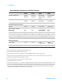
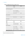
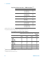
3 Calibration Procedures Output Voltage Quick Check 10 V Q ± 45 mV 0V Q ± 20 mV -10 V Error from Nominal (1 year) ± 45 mV Analog Output Adjustment Install the 34952A module in the mainframe and allow a 1 hour warm- up before performing these procedures. This adjustment procedure sets a zero adjustment and a gain adjustment constant for each DAC output. You must perform all the adjustments on one analog output channel before adjusting the other analog output channel. 1 Install the module(s) in the instrument. 2 Unsecure the instrument for calibration (see page 47). 3 Connect channel 6 DAC output to the DMM input. Set the DMM to measure DC volts. 4 The calibration procedure makes two adjustments per channel. After sending the first command, measure the module output. Send the measured value to the module and advance to the next point. This procedure is summarized as follows: a Send the following command to begin the procedure. CALibration:BEGin:VOLTage 1,(@<channel>) b Measure the module output. c Send the measured value to the module with the following command: CALibration:POINt? <value> d The command returns a “+1” to indicate it is ready for the next point. e Measure the module output. f Send the measured value to the module with the following command: CALibration:POINt? <value> g The command returns a “+0” to indicate the calibration on the channel is completed. 5 Repeat steps 3 and 4 for channel 7. 34980A Service Guide 73