1
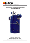
Fulton Boiler Works, (Great Britain) Ltd.)
INSTALLATION, OPERATION, MAINTENANCE
AND PARTS MANUAL
JFS Series - OIL FIRED
STEAM BOILER
This Manual must be available to the boiler operator at all times.
January 2008
In case of Emergency
This boiler has been designed and constructed to meet all of the essential requirements of the applicable
European Directives and subject to proper maintenance should not give occasion to any hazardous
conditions. If such a condition should occur during commissioning or during subsequent operation of
this product, what so ever the cause, then the fuel supply to the boiler should be isolated immediately,
until such time that the fault has been investigated by a competent person and rectified.
WARNING
Steam Boilers are a potential hazard possibly fatal if not properly maintained.
Only Corgi registered personnel are allowed to work on the gas components of this boiler.
It is vitally important that the instructions givenin this manual are strictly adhered to.
Failure to carry out the routine maintenance checks could result in a drastic reduction in the life expectancy of
the boiler.
Continual improvement in boiler design and fittings may result in some of the components used being different
to those in this manual, if in any doubt about individual components or their operation, contact Fulton Service
Department.
NOTE
The Pressure System Safety Regulations 2000
Fulton Boilers fall within the scope of the Pressure Systems Examination Scheme.
Regular inspections are therefore required by a 'Competent Person'.
The scope of the examination and the actual intervals between examinations is at the discretion of the competent person.
It is the responsibility of the user to provide a written scheme of examination for those parts of the system in
which a defect may give rise to danger.
Instructions in this manual are provided for the safe operation and maintenance of the boiler and do not cover
periodic statutory inspections.
For further information contact:
(a)
SAFed
SAFETY ASSESSMENT FEDERATION Limited.
Nutmeg House,
60 Gainsford Street,
Butlers Wharf,
London, SE1 2NY.
(b)
Health and Safety Executive local office.
(c)
Your Competent Person.
JFS Series Oil 01 2008
LIST OF CONTENTS
TITLE
SECTION
INTRODUCTION
1
General
1.1
Technical Data
1.2
INSTALLATION
General
Siting
Ventilation
Flue Outlet
Water Supply
Blowdown Valves
Main Steam Valve
Steam Safety Valve
Water Level Gauge Set
Oil Supply
Electrical Requirements
Steam Pressure Gauge
Commissioning the Boiler
Cleaning Steam Lines and Pressure Vessels
2
2.1
2.2
2.3
2.4
2.5
2.6
2.7
2.8
2.9
2.10
2.11
2.12
2.16
2.17
OPERATION
General
Boiler Controls
Control Panel - Indicator Lights
Filling the Boiler - All Models
Starting the Burner - All Models
Daily Operating Tests
Pump Check
First Low Water Level Check
2nd. Low Water Check Blowdown Procedures
Evaporation Checks
Troubleshooting
3
3.1
3.2
3.3
3.4
3.5
3.6
3.6.1
3.6.4
3.6.5
3.7
3.8
3.9
Maintenance Log
MAINTENANCE
General
Daily
Weekly
Monthly
Three Monthly
Six Monthly
4
4.1
4.2
4.3
4.4
4.5
4.6
GENERAL DATA
5
SPARE PARTS
6
JFS Series Oil 01 2008
SAFETY
The instructions provided for the operation and maintenance of the boiler MUST be observed.
Failure to do so could result in damage to the boiler and serious personal injury.
WARNING
It is the responsibility of the installer to ensure all parts
supplied with the boiler are fitted in a correct and safe
manner.
WARNING
Only qualified persons should be allowed to
operate and maintain the boiler and its
equipment. Boilers should always be drained through
an approved Blowdown Vessel.
WARNING
Do not try to do repairs or any other maintenance
work you do not understand. Obtain a Service Manual
from Fulton or call a Fulton Service
Engineer
WARNING
Do not change the boiler fuel without consulting the
boiler manufacturer.
WARNING
Understand the electrical circuit before connecting or
disconnecting an electrical component. A wrong connection can cause injury and or damage.
WARNING
A defective boiler can injure you or others. Do not operate
a boiler which is defective or has missing parts. Make
sure that all maintenance procedures are completed
before using the boiler.
WARNING
HYDRAULIC TEST RISK OF BRITTLE FRACTURE
Hydraulic testing requires specialist equipment and is
normally only required by engineering surveyors / inspectors. The material the boiler is manufactured from,
has not been impact tested, as it is not a requirement
of BS2790 (boiler construction standard). In order to
ensure the material / pressure vessel does not suffer
from brittle fracture, hydraulic testing should not be
carried out below 5OC.
WARNING
The importance of correct boiler water and feed water
cannot be over emphasised, see the relevant section
in this manual.
CAUTION
LOW FEED WATER TEMPERATURE
Low feed water temperature can result in thermal shock
to the boiler pressure vessel. Return the maximum
amount of condensate and if necessary pre-heat the
feed water. If in doubt consult FBW.
CAUTION
Obey all laws and local regulations which affect you
and your boiler.
WARNING
Non-approved modifications can cause injury and
damage. Contact your Fulton dealer before modifying
the boiler.
WARNING
LIFTING EQUIPMENT
Make sure that lifting tackle complies with all local
regulations and is suitable for the job
You can be injured if you use faulty lifting equipment.
Make sure the lifting equipment is in good condition.
WARNING
Operating the boiler beyond its design limits can damage the boiler, it can also be dangerous. Do not operate
the boiler outside its limits. Do not try to up grade the
boiler performance by unapproved modifications.
WARNING
DANGER FROM HOT SURFACES
Steam Boilers have high temperature surfaces, that if
touched may cause serious burns. Only competent
and qualified personnel should work on or in the locality of a steam boiler and ancillary equipment. Always
ensure the working area and floor are clear of potential
hazards, work slowly and methodically.
WARNING
DANGER FROM INCOMPLETE COMBUSTION
The importance of correct burner adjustment to achieve
low emissions, safe, clean and efficient combustion is
paramount. Poor combustion, where unburnt oil forms
carbon monoxide is both a health hazard, and the
potential risk to the boiler from overheating, caused
by re-burning of the unburnt gas in the secondary
flue passes.
CAUTION
WATER SOFTENER and CHEMICAL TREATMENT
The chemicals required to operate the water softeners and
chemical treatment plants are NOT SUPPLIED by Fulton.
It is the responsibility of the operator to ensure adequate
supplies of chemical are available at all times (including
commissioning).
Costly repairs could be required should the plant
operate without chemicals or the wrong dosage of
chemicals.
JFS Series Oil 01 2008
Optional Variations (where fitted)
Appendix
Spirax High Integrity Level Controls
C
LIST OF ILLUSTRATIONS
TITLE
Oil Fired Steam Boiler
General Arrangement
Typical Installation
Boiler Flue Connection
Boiler Feed Water Arrangements
Boiler Blowdown
Main Steam Valve
Safety Valve
Water Gauges
Oil Supply
Ignition Electrodes
Boiler Top
Steam Pressure Gauge
Nozzle and Ignition Assembly
Commissioning the Boiler
Pressure Control
JFS33 Control Panel
Sight Gauges
Boiler Maintenance
Handhole
Burner Assembly
Flue Cleaning
Boiler Dimensions
Supply Circuit
Ancillary Supply Circuit
Spirax Level Control Circuit
LC Level Control Circuit
TDS and Blowdown Control Circuit
JFS (6J - 30J) Burner Control Circuit
FIG. NO.
SPARE PARTS
Refer to Fulton for required spare parts.
JFS Series Oil 01 2008
1
2
3
4
5
6
7
8
9
10
11
12
13
14
15
16
17
18
19
20
21
22
23
24
25
26
27
28
29
1
1
Steam
Pressure
Gauge
Feed Water
Isolation
Ball Valve
Ultraviolet
Flame Detector
Feed Water
Non-return
Valve
Steam Supply
Valve
Ignition Electrodes
Safety Valve
Oil Feed Line
Water Level
Probes
Water
Column
Probes
Oil Pump
Main Air
Intake
Manifold
Boiler
Control Panel
Sight Gauge
Blowdown
Valves
Feed Water
Pump
Isolator Switch
Water Column
Blowdown valves
Control Box
Isolator Switch
Steam Pressure
Control
Boiler Blowdown
Valve
Cleanout Door
(flame turn around)
Cleanout Handhole
(Water Jacket)
FIG.1 OIL FIRED STEAM BOILER
1
JFS Series Oil 01 2008
1
1
INTRODUCTION
1.1 General
SECTION 1
The Fulton JFS Series Oil Fired Steam Boiler is a vertical two-pass boiler of simple and efficient design and construction, incorporating a larger heat transfer surface than standard boilers it meets the peak demand for steam over a relatively short period of time, ideal for applications such as sterilisers and autoclaves.
The larger steam release surface area, results in a more stable water level under peak load
conditions, producing higher quality steam.
Every care has been taken in the manufacture of the boiler to ensure that quality and reliability standards are maintained. Satisfactory performance can only be ensured if the installation
recommendations, operating routines and maintenance schedules laid out in this manual are
adhered to.
Particular attention should be paid to electrical installation and water treatment.
1.2 Technical Data
for a full specification refer to Section 5.
JFS Series Oil 01 2008
2
2
Steam Pressure
Gauge
Flame Detector
Feed Water
Isolation
Ball Valve
Feed Water
Non-return Valve
Ignition Electrodes
Main Steam Valve
Safety Valve
Water Level
Probes
Oil Feed
Water
Column
Probes
Oil Pump
Main Air
Intake
manifold
Boiler Control
Panel
Sight Gauge
Blowdown Valve
Feed Water Pump
Isolator Switch
Control Box
Door Lock
Water Column
Blowdown Valve
Control Box
Isolator Switch
Steam Pressure
Control
Boiler Blowdown Valve
Cleanout Door
(flame turn around)
Cleanout Handhole
(Water Jacket)
FIG. 2 GENERAL ARRANGEMENT
3
JFS Series Oil 01 2008
2
2
INSTALLATION
SECTION 2
2.1
General
The installation of a JFS Series Oil Fired Steam Boiler should be carried out by competent personnel in
accordance with all relevant safety regulations. It is the responsibility of the installer to ensure that these
regulations are complied with.
2.2
Siting
The boiler house should be sufficiently large to allow easy and safe access to all parts of the boiler for
installation, operation and maintenance purposes. Reference should be made to Section 5 - General
Data to ascertain the relevant dimensions and special note taken of the vertical clearance required for
the removal of the burner.
The flooring must be level, laid in a non-combustible material and be of sufficient strength to support the
boiler.
2.3
VENTILATION
Adequate fresh, clean air is necessary for safe and efficient combustion, and should be provided at high and low level in accordance with IGE/UP/10 Edition 2. It is essential that only fresh air is allowed to enter the combustion air system. Foreign substances, such as combustible and volatile materials in the combustion system can create hazardous conditions.
Note:
(a)
Ensure there is adequate ventilation in the boiler room. Lack of ventilation will create a high temperature and cause control lockout.
(b)
Do not keep exhaust fans running with windows, doors and vents closed, this will interfere with the necessary boiler draught.
(c)
Do not store chemicals such as perclorethylene in the boiler house, the fumes may damage the boiler and flue and cause the burner to lock out on flame failure.
Ventilation requirements
Boiler Model
22
33
55
High Level (cm2)
Low Level (cm2)
420
560
700
835
1115
1395
JFS Series Oil 01 2008
4
5
D
H = 1.5 DX
WA TER
COLUM N
BLOWDOWN
LINE
STANDARD BOILER
TRIM SUPPLIED
WHEN ORDERING
THE BOILER
FIG. 3 TYPICAL INSTALLATION
JFS Series Oil 01 2008
VEN T
SLUDG E
COCK
FILL
FLEXIBLE LINK
OVERFLOW
STRAINER
FEED WA TER
PUMP
ISOLATING
VA LVE
STAINLESS
STEEL
TANK
SET
CHECK
VA LVE
ISOLATING
VA LVE
SIGHT GLASS
OIL RETURN LINE
FITAN ISOLATING VA LVE IN
OIL RETURN LINE ONLY
IF OIL
TANK OR PIPE WORK
ISABOVE BURNER LEVEL
CONDENS ATE RETURN
CLEANOU T
DOOR
FEED WA TER
CHECK VA LVE
BOILER BLOWDOWN
VA LVE
FLUE
SPIGOT
BALL
VA LVE
DRAUGHT
STABILISER
(WHERE
FITTED)
PIPE SAFETY VA LVE
TO SAFE AREA, FITTIN
G
UNIONS AND DRAIN
STEAM SUPPL Y
D = Diameter of flue
Flue
H
Cowl
TO OIL STORAGE T ANK
DRAIN
FU LTON
BLOWDOWN
SEP ARA TO R
OVERFLOW
TO DRAIN
NOTE: A BREAK TANK MAY
BE REQUIRED CHECK TH E
LOCA L WA TER AUTHORITY
BYE-LAW S
MAKE-U P SUPPL Y
CONNECTIONS
OIL FEED
LINE
OIL FIL
TER
(METAL CART RIDGE)
FIRE VA LVE LINE
2
2
2
2
2.4
Flue Outlet
The boiler is supplied with a stainless steel flue spigot that should be inserted into the flue outlet in the back of the boiler and secured with the three angle clips supplied loose in the trim box.
The height and type of flue will generally be subject to local planning regulations and approvals. The following
information is intended to provide assistance where the installation of a simple flue is required. Where multi-
boiler flues or difficulties are experienced, specialist
advice should be obtained.
The flue diameter must be the same or larger than the flue flange provided with the boiler and the outlet should be at least 1 meter higher than the nearest ridge to avoid
down draughts. Where a chimney cowl is fitted, care
should be taken to ensure that the distance between the lowest point of the cowl and the top of the flue is 1.5X the diameter of the flue, and that it is of the terminal cone
type.
Note:
1.
2.
3.
2.5
FIG. 4 BOILER FLUE CONNECTION
If the flue layout is such that it may produce an excessive up-draught, a draught stabiliser
may be required.
Avoid fitting 90deg. elbows whenever possible, if unavoidable compensate by increasing the flue diameter.
Ensure all flue pipes from the boiler to the main flue have a rising pitch.
Water Supply
The quality of the water used in the boiler will affect the life and performance of the boiler. Feed water contains solids and dissolved gases, these may promote encrustations of scale; foaming, priming, surging; corrosion and pitting; or caustic embrittlement. To prevent this happening it is strongly
recommended that a reputable water treatment concern is consulted prior to commissioning the boiler.
Note: see Section 5 Water Treatment.
Feed Water
Check
Feed Water
Stop Valve
Valve
Dip Pipe
Connect the feed water pump discharge to the check valve inlet with 25 mm. bore pipe (this may be reduced to 15 mm, where the discharge pipework is shorter than 4m in total. the pump suction pipework must remain at 25mm
minimum diameter and be as short as possible), insert the stop valve supplied, between the boiler and the check valve.
Feed
It is essential to protect the feed water pump Water
from damage by foreign matter, a strainer should
Supply
therefore be fitted in the pump suction pipework
Care should be taken to ensure the pipework is properly aligned and not placing any strain upon FIG. 5 BOILER FEED WATER ARRANGEMENT
the feed water pump.
Note: 1.
The boiler feed water pump may contain an inhibitor and this should be flushed from the pump prior to fitting the pump to the
boiler. Failure to do so may result in water bounce or foaming due to the inhibitor forming a
seal in the boiler.
2.
If the boiler is to be operated with little or no condensate return, consideration should be given to pre-heating the feed water. If in doubt consult Fulton Boiler Works.
3.
The feed water inlet connection on some boilers is located on the left hand side of the boiler below the sight glass assembly.
JFS Series Oil 01 2008
6
2
2
2.6
Blowdown Valves
There are three blowdown valves on the boiler
(four if two water gauge sets are fitted), the
boiler blowdown valve at the rear of the boiler, the water column blowdown valve and the water gauge blowdown valve.
All of these valves must be connected to a
blowdown receptacle of approved design.
Regulations exist covering such items and care must be taken to ensure compliance with these regulations. If in doubt regarding blowdown
arrangements, consult your Fulton agent.
FIG. 6 BOILER BLOWDOWN
2.7
Main Steam Valve
The main steam stop valve should be inserted in the steam line approximately 12in. (305 mm) from the top of the boiler.
FIG. 7 MAIN STEAM VALVE
7
JFS Series Oil 01 2008
2
2
2.8
Steam Safety valves
Safety Valves are factory fitted and preset, they MUST NOT be adjusted. The discharge outlet should be piped to a safe discharge point and the piping so arranged that any condensate trapped in the pipework will drain away from the valve.
(a)
The lift pressure is indicated on the safety valve. (Do not adjust).
(b)
The safety valve fitted to the boiler is designed to prevent the boiler exceeding it's design pressure.
(c)
Any system connected to the boiler not capable of accepting boiler pressure must be protected by a separate safety valve set to the required pressure.
Long radius fittings to be used with a minimum of 6 diameters to the first fitting.
(d)
WARNING
Factory fitted safety valves are preset to protect the
boiler only and must not be used to protect any other
items not capable of accepting boiler pressure.
FIG. 8 SAFETY VALVE
2.9
Water Gauge Set
(The design may vary from that illustrated)
Boilers are normally supplied with two
complete water gauge sets. The water gauge blowdown cock should be connected to the
auxiliary blowdown line from the water column blowdown valve in soft copper tubing.
The connection to the gauge cock is
6mm (0.25in.).
Numbers may vary due to individual countries regulations.
FIG. 9 WATER GAUGES
JFS Series Oil 01 2008
8
2
2
Oil supply
Ignition
Transformer
Electrical
Connection Box
Oil Supply
Valves
Adjustable
Air Control
Oil Pump
Flame detector
location
Ignition
electrodes
FIG.10 OIL SUPPLY
Secondary air
damper
FIG.11 IGNITION ELECTRODES
Flame Detector
Safety Valve
Water Level
Probes
Burner Assembly Cover
Oil Supply
Connections
Ignition Electrodes
FIG. 12 BOILER TOP COMPONENTS
9
JFS Series Oil 01 2008
Steam Supply
Pipe
2
2
2.10 Oil Supply
The positioning of the oil storage tank will be dependent on site conditions and local regulations. The
burner fuel pump is of the bypass type requiring the installation of feed and return lines between the oil
storage tank and the boiler. These lines should be in tubing of a minimum bore of 10 mm.
A fire valve, stop valve and check valves should be inserted in the oil feed line.
To avoid blockages in the fuel pump and burner nozzle, a metal cartridge oil filter should be fitted.
Fibrous cartridge filters are not recommended.
The final connections between the fuel pump and the feed and return lines should be made with the flexible fuel lines supplied. If the oil storage tank is positioned higher than the boiler, a non-return
valve should be fitted to the return line.
To overcome suction problems at the fuel pump, all vertical lifts in the feed pipe should be made as
close to the boiler as possible. The burner fuel pump pressure is preset at the factory and should not
require adjustment.
2.11 Electrical Requirements
An individual wiring diagram for the boiler is located on the inside cover of the control box.
When referring to the electrical specification of the boiler, the reference number located on the rear inside wall of the control box and the wiring diagram number should be quoted.
The audible alarms provided are mounted on the side of the control panel, if not audible they should be repositioned where they can be heard by a person competent to take the appropriate action should the alarm be activated.
Unless otherwise specified, the alarms supplied will be mains voltage models. Unless otherwise specified all models are supplied with burner motors and feed water pump motors arranged for operation on a three phase supply.
The power ratings and requirements are given in Technical Data - Section 5.
JFS Series Oil 01 2008
10
2
2
Steam Pressure Gauge
Plug
Steam Cock
Test Point
Syphon
F03210
FIG. 13 STEAM PRESSURE GAUGE
2.12 STEAM PRESSURE GAUGE
The steam pressure gauge assembly should be assembled in accordance with Fig. 9 using a suitable sealant on all joints.
The gauge should be facing towards the electrical control box and/or the operator of the boiler.
Screw the assembly into the top of the boiler and connect the copper tube from the pressure controller located on the side of the control box to the nipple provided on the assembly.
2.16 Commissioning the Boiler
It is essential that the commissioning procedures listed below are carried out by a Fulton Service
Engineer who will have the necessary experience and testing equipment to ensure that the installation
is not only correct, but is operating safely and at optimum efficiency.
FLUE COMMISSIONING
Prior to initial firing of the boiler, the flue must be checked for leaks.
This is done by BOTH of the following methods:
Visual Inspection
Check joints between all flue sections for quality of seals. Where the flue passes through the structure of the building use your judgement as to the integrity of this section of the flue.
Smoke Test
With the flue capped, the drain stabilizer pipe (if fitted) blanked and a smoke generator inserted into the flue, there should be no smoke visible from the flue.
If either of these tests fail or at any time during boiler operation, there is doubt about the integrity of the flue, shut down the boiler and contact Fulton Boiler Works Immediately.
11
JFS Series Oil 01 2008
2
2
2.16 COMMISSIONING THE BOILER - continued
INSPECTION
(a)
(b)
Ensure the boiler has been washed out after installation.
Conduct a water analysis before operating the boiler.
Examine the probes in the water column and the boiler shell.
Replace any damaged probes.
(c)
Replace the burner and reconnect the cooper oil line(s) to the oil nozzle assembly, ensuring
these connections are tight. Reconnect the ignition leads and replace the sensor.
Ensure all wiring connections are correct and all terminal screws are tight.
(d)
Remove the burner and check the electrodes have not been damaged and that their settings are correct. If the burner is fitted with a photocell, remove it and check for damage.
High Fire Oil Supply
Low Fire (Start)
Oil Supply
Burner Plate
Electrodes
Electrodes
View on
arrow 'A'
5mm
12mm
Electrode settings
relative to nozzles
130mm
5mm
Electrode Tips
Bent to align with
Low Flame (Start)
oil supply nozzle
Arrow 'B'
Nozzle Manifold
5mm
High Fire Oil Supply
300mm
5mm
80O Spray
Arrow 'A'
80O Spray
12mm
5
300mm
Fuel Nozzle
View on arrow 'B'
12mm
Low Fire Oil Supply
SINGLE NOZZLE
SINGLE-STAGE LIGHT
10E - 30E
DOUBLE NOZZLE
TWO-STAGE LIGHT
40E - 60E
Note: Always place the highest value nozzle
(engraved on the side of the nozzle) into the low
fire oil supply port in the manifold.
FIG. 14 NOZZLE AND IGNITION ASSEMBLIES
JFS Series Oil 01 2008
12
2
2
Steam Pressure
Gauge
Feed Water
Non-return Valve
Feed Water
Stop Valve
Flame Detector
Main Steam Valve
Ignition Electrodes
Oil Feed Line
Safety Valve
Water Level
Probes
Air Intake
Manifold
Boiler Control
Panel
Sight Gauge
Blowdown
Valves
Feed Water Pump
Isolator Switch
Control Box
Door Lock
Water Column
Blowdown Valve
Control Box
Isolator Switch
Steam Pressure
Control
Boiler Blowdown Valve
Cleanout Door
Cleanout Handhole
(Water Jacket)
FIG. 15 COMMISSIONING THE BOILER
13
JFS Series Oil 01 2008
2
2
2.16 COMMISSIONING THE BOILER - continued
(e)
A barometric type draught stabiliser (if fitted in the flue) should be set for a draught of
- 0.01in. to - 0.02in. (- 0.025mb to - 0.050 mb) of water column pressure with the burner off.
(f)
Open all the valves in the water feed line.
(g)
Open all the valves in the feed water line.
FEED PUMP
Close the isolating valve on the discharge side of the pump. Remove the priming plug from the
pump head and slowly fill the pump with water. Replace the priming plug and tighten securely. See the correct rotation of the pump on the motor fan cover. Start the pump and check the direction of rotation.
Vent the pump by means of the vent valve in the pump head. At the same time, open the discharge
isolating valve a little. Continue to vent the pump. At the same time, open the discharge isolating
valve a little more.
Close the vent valve when a steady stream of water runs out of it.
Completely open the discharge isolating valve.
The bypass valve located in the drain plug may be opened during the filling procedure, close the
bypass when the operation is stable.
DO NOT ALLOW THE PUMP TO RUN DRY.
(h) Open all the valves in the water feed line.
Switch on the feed water pump motor and fill the boiler.
The operation of the pump controls should be checked by using the boiler blowdown valve (located
at the rear of the boiler).
When the water sight level gauge is reading two thirds full, the pump will stop.
Open the boiler blowdown valve and slowly drain the boiler. When the water level falls below
the PUMP ON probe, the pump should start. If the pump does not start check the probe connections.
Close the boiler blowdown valve.
(i)
Close the boiler blowdown valve.
(j)
Start the burner as detailed in Section 3 - Operation. Allow time for the fuel pump to prime itself.
(k)
After the burner has been firing for approximately five minutes, adjust the main air control gate to obtain a clean combustion.
(l)
Observe the flame through the peephole between the electrodes and adjust the primary air
control so that the flame cannot be seen 'backing up' the blast tube. Adjust the air main
control to obtain a full swirling flame shape brushing the wall of the furnace by observing the flame through the eye glass in the burner plate.
(m)
Check the operation of the low water safety controls as detailed in Section 3 - Operation.
JFS Series Oil 01 2008
14
2
2
2.16 COMMISSIONING THE BOILER - continued
(n)
Adjust the steam pressure control to suit the boiler application. It should be borne in mind that boiler are designed to operate most efficiently at their maximum operating temperature. When boilers are to be operated below a pressure of 80 psi (5.5 bar) consideration should be given to the fitting of a pressure reducing set (see Section 2.8 - Steam Safety Valves).
If the pressure control is fitted with a differential scale:
(see OEM literature in section 5)
(i)
Set the main scale pressure to the pressure
indicated on the boiler data plate.
(ii)
Set the differential scale to it's minimum pressure.
If the pressure control has a fixed differential,
e.g. no adjustable differential scale, set the main
scale to the maximum pressure required.
Note: When boilers are fitted with a sequence control:
(i)
(ii)
Set the main scale and differential scale as above.
Set the set-back pressure control to the required
set-back pressure.
FIG. 16 PRESSURE CONTROLLER
Note: In order to utilize the maximum flash steam capability of the boiler it is essential that the boiler is
operated at the maximum working pressure (10.34 bar) and then pressure reduced down to the required system
pressure.
2.17 CLEANING STEAM LINES AND PRESSURE VESSELS
During the first week of boiler operation, clean all oil and dirt from the boiler, the steam line and
condensate return line.
(a)
Disconnect the condensate return pipe adjacent to the condensate return tank.
(b)
Direct the returns to a floor drain or other safe discharge point and make safe.
(c)
Leave in this position for one week to allow all impurities to flush through.
(d)
Drain the boiler completely each day.
(e)
15
After the week is completed, drain and flush the condensate return tank, removing all installation sediment. Reconnect the condensate return pipe to the condensate return tank.
JFS Series Oil 01 2008
3
3
OPERATION
SECTION 3
3.1
GENERAL
DRYING OUT TIME
The refractory casing of the boiler is made from a material that uses a high proportion of water in the mixing process. Whilst some of this water is driven off by chemical reaction and the initial test
firing, the refractory is still 'wet' when the boiler is delivered. For the first few days after the boiler is commissioned and in service, water will be seen running from the bottom of the casing and from around some branch pipes. This is perfectly normal and part of the final drying process.
3.2
BOILER CONTROLS
The following brief description of the controls used on the JFS Series oil fired boiler is intended to provide the operator with a basic understanding of the operating principles, which is essential for the continued efficient operation of the boiler.
The following instructions are given for the guidance of the operator in the use of the JFS Series oil fired boiler and to provide adequate information to ensure that when the boiler is put into use it will be done safely and without risk to health.
Where original equipment Service Manuals are supplied, they must be read and understood in
conjunction with this manual. All Warnings and Cautions must be observed.
WARNING
The control circuit live light is derived from a single phase.
It is possible that with the control phase down or a defective
bulb the other phase could be live.
Always Isolate the supply before investigating any fault.
Note:
All the controls are of the ‘fail-safe’ type and are wired in series; failure of any one will automatically shut down the boiler.
Low Water Safety Relays and Feed Water Pump relays
These relays operate in conjunction with probes suspended in the boiler and water column to automatically maintain the level of water in the boiler and to cut-off the burner should the water level fall to an unsafe level.
Steam Pressure Control(s).
Located on the control panel box and connected to the steam pressure gauge assembly by copper tubethe
pressure regulator controls the on/off cycle of the burner, shutting the burner off when maximum
pressure is reached and switching it on when the steam pressure falls.
Burner Programmer
This is the main control in the panel box. The programmer, in conjunction with a sensing device, ‘supervises’ the ignition sequence, proves the flame is satisfactory and finally ‘monitors’ the established flame. Should any fault occur, either during the ignition sequence or during normal running, the programmer will immediately go to ‘lockout’ and the burner will shut down.
JFS Series Oil 01 2008
16
3
3
3.2
BOILER CONTROLS continued.
Fuel Pump
Mounted on the burner scroll and driven by the burner motor, the fuel pump delivers oil to the burner nozzles at the correct pressure to allow complete atomisation and therefore combustion.
PUMP CONTROL
Pump Interrupt/Pump Run Switch.
Fitted on the left side of the control panel, used to override (switch off) the pump controls during evaporation tests.
STAR T
PUMP
LO W
WA TER
CIRCUIT
BURNE R
ALAR M
ON
ON
FLAME FAILURE
OIL
OIL
VA LVE
VA LVE
IGNITION
OFF
L/W RESET
ONLY
PUMP
OF F
& BOILER
ALARM
6-30J oil
FIG. 17 JFS33 CONTROL PANEL
17
JFS Series Oil 01 2008
3
3
3.3
INDICATOR LIGHTS
Indicator lights are fitted to the control panel as an additional aid to the operator. The meaning and operating sequence of these lights is as follows:
Start / Low Water Reset
This switch is used to start the boiler and to reset the low water alarm. When the switch is pressed to initiate the start-up sequence, the low water alarm lamp also illuminates and the low water audible alarm sounds. Keeping the switch depressed for approximately 2 seconds cancels the low water alarm and initiates the burner start sequence.
Illumination of this switch and sounding of the audible alarm at any other time other than at switch on indicates that the boiler has gone to a lockout (safe condition) due to low water. Once the water in the boiler has been restored to a safe operating level, pressing the switch will reset the controls.
Circuit On
Indicates that power is being supplied to the control panel.
Low Water Alarm (1st. low water).
This light will energise, when the boiler is switched on and the water level is between 1st. low water and 2nd. low water. A light will illuminate and a pulsing alarm sound.
Low Water Reset (2nd low water).
The 1st. low water light and alarm are replaced by the 2nd. low water light and a continuous alarm, indicated by the low water reset switch.
The second alarm must be reset, the first alarm will be automatically reset by the return to normal water level.
Ignition
Burner On
This lamp indicates that the burner is running and that the flame is being monitored by the
burner programmer.
Flame Failure Alarm (reset)
This switch will illuminate if the burner goes to a lockout condition due to flame failure. Pressing the switch will reset the burner controller.
WARNING
No more than two attempts should be made to start the boiler by resetting the
flame failure alarm (reset) Further attempts could cause the boiler and flue
system to fill with vaporized oil which could cause an explosion.
This lamp indicates the ignition transformer has been energised, it will remain illuminated for
5 - 10 seconds approximately during the ignition sequence.
Oil Valve
The two lamps provide a visual indication that the magnetic oil valves have been energised.
JFS Series Oil 01 2008
18
3
3
3.4
FILLING the boiler - All Models
Carry out the following procedure on the initial start up of the boiler and on every subsequent occasion when restarting the boiler after a shut down:
(a)
Ensure that the main steam stop valve is OPEN.
(b) Ensure that the steam pressure gauge isolating valve is OPEN.
(c) Ensure that the oil flow and return valves are OPEN, that there is an adequate oil supply in the oil tank, and that the burner oil pump has been vented.
(d) Ensure that all the valves in the water feed line are OPEN.
(e) Ensure that the main blowdown valve is CLOSED.
(f)
Ensure that the water level gauge isolating valve(s) is OPEN.
(g)
Ensure that the water level gauge blowdown valve(s) is CLOSED.
(h)
Ensure that the column blowdown valve is CLOSED.
(i)
Ensure that the boiler and pump switch is in the OFF position.
(j)
Ensure that all appropriate electrical isolators are switched ON.
(k)
Ensure the pump interrupt switch is in the PUMP RUN position.
CAUTION
The feed pump seals are water cooled.
The pump must never be allowed to run whilst dry, irreparable damage may result.
Ensure the pump is fully primed before energising the motor.
(l)
Press the boiler/pump switch to the PUMP ONLY position.
Note:If the boiler water level is below its correct level, the water pump will operate. When the water reaches the correct level (two thirds up the water level gauge sight glass), the pump will stop. If the water level is above the top of the water level gauge sight glass, drain off until the level is in the middle of the water level gauge sight glass.
3.5
Starting the Burner
(a)
CLOSE the main steam stop valve.
(b) Press the control switch to the PUMP AND BOILER position. The low water audible alarm will sound, and the low water reset switch and low water alarm lamp will illuminate.
(c)
Press the low water reset switch for 2 seconds maximum. The audible alarm will silence and the alarm lamps will extinguish. The burner start sequence will commence.
(d)
After a maximum of one minute, the burner should be firing and the burner on lamp should illuminate.
19
JFS Series Oil 01 2008
3
3.5
3
Starting the Burner - continued.
(e)
When the boiler has achieved the required (set) pressure, the main steam isolating valve should be slowly opened allowing steam to enter the system distribution pipework.
WARNING
The system should be raised to temperature slowly to allow
for expansion and to avoid thermal shock and water hammer.
This can be achieved by one of two methods.
1.
Crack open the main steam valve and allow the system to heat up slowly, (minimum
15 minuets) before fully opening the main steam valve.
2.
Open the main steam valve when starting the boiler, allowing the boiler and system to heat up together.
Note: This can lead to water logging of the steam lines until full pressure is achieved.
3.6
Daily OPERATING TESTS (3.6 - 3.7)
Visually inspect the steam and feed water pipework, valves and fittings for signs of leakage. If leaks are suspected shut the system down and evacuate the system to atmospheric pressure before
attempting to repair the leaks. The following procedure should be carried out by a competent person to ensure the correct functioning of the water level and low water safety controls. Where possible, the boiler should not be under steam pressure during these tests, (see 3.6.5.g.2.).
Note: Ensure that the water level is maintained during the pressure build up. If any part of the equipment is not operating correctly, the fault should be investigated before the boiler is used. Ensure that all blowdown pipework is safe and discharged to a blowdown receptacle.
3.6.1. Pump Check
With the burner firing and the pump not running, lower the water level in the boiler by opening the main boiler blowdown valve.
As the water level falls, visible in the sight glass, and before the low water lock out position is reached the water pump should start to run. When this happens close the main boiler blowdown valve.
The water pump should continue to run and re-fill the boiler to the correct level and stop.
3.6.4 First Low Water Level (for boilers fitted with Spirax High Integrity Level Controls, see Appendix 'C')
(a)
Ensure the following:
The burner is firing.
The water level is correct in the boiler.
The water pump is not running.
(b)
Switch the pump off (Pump Interrupt) at the pump interrupt/pump run switch.
(c)
OPEN the main blowdown valve.
(d) When the water level nears the bottom of the water level gauge sight glass, the low water alarm should sound, the low water alarm lamp should illuminate and the burner should stop firing. When this happens, CLOSE the blowdown valve IMMEDIATELY.
(e)
Switch the pump to RUN at the main pump interrupt/pump run switch. The pump should run and refill the boiler. When the water level in the boiler rises above the first low water level, the low water level lamp should extinguish, the audible alarm should silence and the burner start sequence should commence automatically.
The pump should run until the boiler water level is correct and then stop.
JFS Series Oil 01 2008
20
3
3
3.6.5 2nd. Low Water Check
(for boilers fitted with Spirax High Integrity Level Controls, see Appendix 'C')
(a)
Ensure the following:
The burner is firing.
The water level is correct in the boiler.
The water pump is not running.
(b)
Switch the pump OFF at the pump override switch.
(c)
OPEN the main blowdown valve.
(d)
When the water level nears the bottom of the water level gauge sight glass, the LOW WATER ALARM lamp should illuminate, the low water audible alarm should sound and the burner should stop firing.
(e)
Continue to blow down. As the water level falls nearer the bottom of the water level gauge sight glass, the LOW WATER RESET switch should illuminate and the second audible low water alarm should sound.
(f)
CLOSE the main blowdown valve and switch the pump ON at the pump override switch.
The water pump should now start to run and refill the boiler. Once filled to the correct level the water pump should stop. The low water alarm should continue to sound, the LOW WATER
RESET switch and LOW WATER ALARM lamp should remain illuminated and the burner should NOT start.
(g)
When the water level in the boiler is correct, the burner can be restarted by depressing the LOW WATER RESET switch for a maximum of 2 seconds.
1.
The First and Overriding low water checks can be carried out in one operation to reduce the blowdown time and possible interruption to the steam supply.
2.
Where the water level tests are to be carried out at full pressure, evaporate the water down to 1st. low level as in 3.8, blowdown the boiler from 1st. to 2nd. low water.
The purpose of adopting this procedure is to prevent steam and water being expelled from the blowdown vessel vent because of prolonged blowdown.
21
JFS Series Oil 01 2008
3
3
3.7
BLOWDOWN PROCEDURES (Daily tests)
Keep the boiler, water gauge, water column and interconnecting pipework free from sludge and scale buildup by blowing down in the following manner:
Note: Where a boiler is operating continuously at steam pressure, advice should be sort from Fulton
regarding the appropriate blowdown procedure.
(a)
Start the boiler and generate not more than 10psi of steam.
(b) Shut off both the burner and the pump.
Boiler Blowdown
(a)
Fully OPEN the boiler main blowdown valve for not more than 5 seconds.
(b) CLOSE the valve.
Note: Where high levels of suspended solids are produced, longer and/or more frequent blowdown may be
required.
Water Column Blowdown
Note: The water column contains the pump ON/OFF probe, which is not safety locked.
(a)
Switch the pump off at the pump interrupt/pump run switch.
(b)
Open the water column blowdown valve for 5 seconds.
(c)
Close the water column blowdown valve.
Wait for 10 seconds for the water in the boiler to stabilise after blowdown.
Switch the pump on at the pump interrupt/pump run switch.
(d)
JFS Series Oil 01 2008
22
3
3
3.7
BLOWDOWN PROCEDURES (Daily tests) - continued.
Water Gauge Blowdown
(a) Blowdown the water gauge, set 1.
1. Open the gauge glass blowdown valve A
2. Close (for approx. 3 seconds) the top gauge valve B
3. Open valve B
4. Close (for approx. 3 seconds) the bottom gauge valve C
5. Open valve C
6. Close valve A
Repeat for gauge set 2
On completion of the blowdown procedure ensure that all
isolation valves are OPEN and all blowdown valves CLOSED.
Note: Where a Boiler is operating continuously at steam
pressure, advice should be taken from a Fulton agent
as to the appropriate blowdown procedure.
Water Level Gauge
Set 2
WORKING
POSITION
STEAM
BLOWDOWN
B
B
B
WATER
BLOWDOWN
B
C
C
C
A
A
A
C
F03200
Water Level Gauge operating positions.
A
Water Level Gauge
Set 1
Fig. 18 WATER LEVEL SIGHT GAUGE BLOWDOWN
23
JFS Series Oil 01 2008
3
3
3.8
EVAPORATION CHECKS
With the boiler running under normal load conditions, and the pump stopped having just completed a refill cycle:
(a)
Ensure that the boiler water level is correct.
(b)
Switch the pump OFF at the pump interrupt / pump run switch.
If it is required to check the second low water alarm, wait a further period for the LOW WATER RESET switch to illuminate.
When the check is complete, proceed as follows:
(a)
Switch the pump ON at the pump interrupt / pump run switch.
(b)
Press the low water reset switch. The pump will start to refill the boiler.
If the pump starts to run at any time during the test then the test must be abandoned and restarted from the beginning.
The water level in the boiler will lower through natural evaporation. When the level nears the bottom of the water level gauge sight glass, the first low water alarm will sound, the low water alarm lamp will illuminate and the burner will shut down.
JFS Series Oil 01 2008
24
3
3
3.9
TROUBLESHOOTING
Problem
Cause
Remedy
Ignition Failure 1. Oil tank empty 2. Power Supply
3. Ignition Electrodes
4. Transformer
5. UV Detector
6. Loose wire connection
7. Burner Control
8. Oil nozzle clogging
9. Faulty Oil Pump
Refill the oil tank. A slight delay in the re-priming of the fuel pump may cause the burner
programmer to require resetting before the boiler operates satisfactorily.
Check fuse or Circuit breaker.
Reset or replace as required.
Check electrodes for carbon build-up, clean if required. Check settings adjust if required. Check for cracks in porcelain, if found, replace.
Check voltage between transformer leads at terminal block to be sure transformer is live.
Check for ignition interference.
Check connections to all components.
Check voltage between pilot terminal and neutral and ignition terminal and neutral. Check must be made before control locks out on safety. If no power, replace control.
Check oil nozzle(s), clean or replace as necessary.
Check to see if oil is being pumped to the boiler nozzle. Repair or replace as necessary.
Flame Failure 1. Power Supply
(see note )
2. Ignition Electrodes
3. Main Air Adjustment 4. UV Scanner
5. Contact open on
air safety switch
6. Scanner wiring
reversed at panel
7. Oil Supply
8. Oil Valve
9. Oil Pump 10.Loss of Oil Prime
Check fuse or Circuit breaker.
Reset or replace as required.
Check electrodes for carbon build-up, clean if required. Check settings adjust if required. Check for cracks in porcelain, if found, replace.
Check air adjustment. Air may be blowing flame away from the UV detector. Open primary air until fire brushes the furnace wall.
Check for dirt on scanner, clean as required.
Check for proper location of detector.
Adjust to proper setting
Change to correct terminals.
Check oil level in supply tank, ensure it is not below intake line. Fill tank with oil. Check for clogged nozzle. Clean or replace. Check oil filter and replace if necessary.
Check the voltage between oil valve neutral at terminal block to be sure oil valve is getting power.
Check for clogged strainer or filter. Remove and clean. Check for slipping or broken coupling. Tighten or replace.
Check for seized pump shaft. Replace.
Check all lines for possible air leak in intake line and tighten. Check the intake line is not restricted, replace.
Note: One of the most common causes of flame failure is dirt/sediment in the oil filter, oil lines, solenoid
valves or nozzle, caused by a new delivery of oil. If the oil tank level is allowed to fall near to the bottom of
the tank it is highly probable that sediment on the bottom of the tank will be disturbed and mixed in with the
new oil delivery, especially if the delivery rate is too fast.
25
JFS Series Oil 01 2008
3
3
3.9
TROUBLESHOOTING - continued.
Problem
Cause
Remedy
Boiler Fails to Start 1. No Power
2. Pressure Control
Check fuse or circuit breaker. Reset or replace as necessary.
Disconnect all power to the controller. Disconnect the wires from the controller. connect an ohmmeter between the switch terminals. Lower the set point of the controller, the switch should make. raise the set point and re-check, switch should break. if the controller operates improperly, replace it.
Burner Cut-off 1. Oil tank empty 2. Power Supply
3. Ignition Electrodes
4. UV Detector
5. Faulty Air Switch
6. Faulty Level Control
7. Oil Nozzle
8. Transformer
9. Burner Control
10.Pressure Control
Refill the oil tank. A slight delay in the re-priming of the fuel pump may cause the burner
programmer to require resetting before the boiler operates satisfactorily.
Check fuse or Circuit breaker.
Reset or replace as required.
Check electrodes for carbon build-up, clean if required. Check settings adjust if required. Check for cracks in porcelain, if found, replace.
Check for dirt on detector, clean as required.
Check for proper location of detector.
Check for faulty air switch by jumpering the two air switch leads at the terminal block. If the boiler starts and runs with the jumper in place, the air switch should be replaced.
Check the level control relays are securly mounted on their bases. Check the power supply to each. The relays may be checked by swopping positions and checking they are both functioning.
Check for clogged nozzle, clean or replace.
Check voltage between transformer neutral at terminal block to be sure transformer is being powered.
Check voltage between pilot terminal and neutral and ignition terminal and neutral. Check must be made before the control locks out on safety. If no power replace control.
Disconnect all power to the controller. Disconnect the wires from the controller. connect an
ohmmeter between the switch terminals. Lower the set point of the controller, the switch should make. raise the set point and re-check, switch should break. if the controller operates improperly,
replace it.
JFS Series Oil 01 2008
26
3
3
3.9
TROUBLESHOOTING - continued.
Problem
Cause
Poor Combustion 1. Refractory Bricks
2. Stainless Steel Ring 3. Main Air Adjustment 4. Secondary Air Adjustment.
5. Draft
6. Dirty Flue 7. Negative Room Pressure
8. Oil Nozzle
9. Oil Pump Remedy
Check the bricks are not plugged with soot or broken into pieces. Clean and replace as required.
Check to ensure the ring is present and fits
securely against the furnace wall.
Check air adjustment. Open main air until fire brushes the furnace wall.
Check main air adjustment to see if it has moved. Adjust as necessary and tighten in position. Check CO2 and O2 level.
Check draft is neutral.
Consider installing a barometric damper if the draft is too strong.
Check flue for Carbon build-up or blockage. Clean flue passages with brush.
Ensure no exhaust fans are running in the boiler room.
Check for blocked nozzle, clean or replace as necessary.
Check for blocked strainer or filter. Remove or clean. Check for slipping or broken coupling. Tighten or replace. Check for seized pump shaft. Replace.
Burner back fires 1. Refractory Bricks Check the bricks are not plugged with soot or broken into pieces. Clean and replace as required.
2. Ignition Electrodes Check electrodes for carbon build-up, clean if required. Check settings adjust if required. Check for cracks in porcelain, if found, replace.
3. UV Detector Check for dirt on scanner, clean as required.
Check for proper location of detector.
4. Draft Problem Check draft is neutral.
Consider installing a barometric damper if the draft is too strong.
5. Negative Room Pressure Ensure no exhaust fans are running in the boiler room.
6. Primary Air Adjustment Check air adjustment. Air may be blowing fire away from flame detector.
7. Oil Valve(s) Check for leaking oil valve(s) and replace.
8. Loss of Oil Prime Check all lines for possible air leak in intake line and tighten. Check for possible restricted intke line. Replace.
9. Loose Oil Fittings Check all fittings and tighten.
10.Blocked Oil Filter Check and clean or replace.
11.Blocked screen in Oil Pump Check and clean or replace.
12.Blocked Flue Check flue is not blocked, clean as required.
Check draft at flue.
13.Vacuum on Pump Check for too high a vacuum on the pump. Check oil lines and distance from tank to boiler. Repaire or replace as necessary.
14.Hole in suction line Check and replace as necessary.
27
JFS Series Oil 01 2008
3
3
3.9
TROUBLESHOOTING - continued.
Problem
Cause
Boiler will not 1. Oil tank empty maintain pressure
2. Oil Nozzle
3. Oil Valve
4. Oil Pump 5. Dirty Flue 6. Pressure Control
7. Scale buildup in boiler
8. Refractory Bricks
9. Steam Traps blowing through
10.Boiler size
Remedy
Refill the oil tank. A slight delay in the re-priming of the fuel pump may cause the burner
programmer to require resetting before the boiler operates satisfactorily.
Check for blocked nozzle. Clean or replace.
Check voltage between oil valve leads at terminal block to be sure oil valve is getting power.
Check for blocked strainer or filter. Remove and clean. Check for slipping or broken coupling, tighten or replace. Check for seized pump shaft. Replace the pump.
Check flue for Carbon build-up or blockage. Clean flue passages with brush.
Disconnect all power to the controller.
Disconnect the wires from the controller.
Place an OHM meter between the switch terminals. Lower the set point of the controller, the switch should make. Raise the set point and recheck, switch should break. If the controller operates improperly, replace it.
Consult Fulton.
Check the bricks are not plugged with soot, cracked or broken into pieces. Clean and replace as required.
Check traps, clean or replace as required.
Boiler may be undersized.
JFS Series Oil 01 2008
28
3
3
3.9
TROUBLESHOOTING - continued.
Problem
Cause
Boiler is Surging 1. Steam Traps blowing through.
2. Scale buildup or
lime deposits.
3. Too much water treatment.
4. Too much of a load.
Remedy
Check traps, clean or replace as required.
Call water treatment company and consult
the factory.
Dump the return tank and flush the system.
Test the water treatment.
Check total equipment load against the boiler output. Decrease amount of equipment being used.
Boiler Rumbles 1. Draft Problem
2. Too much main air.
3. Air or water in the oil.
Boiler pushing 1. Steam Traps
water with steam 2. Too much water treatment.
Check draft is neutral. Consider installing a barometric damper if the draft is too strong.
Adjust main air.
Check tank and lines for water or leaks.
Pump will 1. Dirty Probes.
not cutoff 2. Relay failed. 3. Earth connection.
Clean or replace as required.
Check relay is secure on its base, if so
replace the relay.
Check for tightness and clean.
Pump runs but 1. Vapour locking
does not put of pump.
water in the boiler 2. Blocked feed water line
Allow system to cool down, check steam traps
and check to be sure return lines are not
insulated. Check return tank temperature, if it is above 82OC vapour locking of the pump will occur. Inspect check valves. Clean and replace as needed. Replace pump with multi-stage centrifugal pump able to cope with 121OC.
Check feed water line is not blocked, clean as required.
Water pump runs 1. Scale on probes.
intermittently 2. Bad pump contactor.
3. Pump Motor damaged.
Check probes, clean as required.
Check to ensure the contactor is live.
Check to ensure the contactor coil is being pulled in. Replace as required.
Check the pump circuit is live. If the circuit is live but the pump is not running, replace the pump.
Boiler contiues 1. Oil Valve defective
after shut down
Oil fumes coming 1. Bad draft condition
out around the oil
pump housing 2. Venting of room
on shut down Boiler flooding 1. Pump does not shut off.
2. Relay failed. 3. Earth connection.
4. Vacuum created
with the boiler off.
Check traps. Clean or replace as required.
Dump the return tank and flush the system.
Test the water treatment.
Check the valve is opening and closing.
Clean or replace as required.
Check the draft with a gauge, should read neutral.
May need to install a barometric damper.
Ensure the boiler room doors are closed and the recommended vents are clear.
Dirty probes, clean or replace as required.
Check relay is secure on its base, if so
replace the relay.
Check for tightness and clean.
As the boiler cools it pulls water from the system.
To prevent this, add an anti-vacuum valve on the steam gauge assembly piping, this valve closes under pressure and opens under vacuum.
29
JFS Series Oil 01 2008
3
3
Fault
Ignition
Failure
Flame
Failure
Burner
Cutoff
Poor
Combustion
Cause
Burner
Back
Fires
Boiler
will not
Maintain
Pressure
Boiler
will not
Maintain
Water
Power Supply
Oil Supply
Refractories
S.S. Ring
Ignition Electrodes
Oil Nozzle
Main Air Adjustment
Oil Valves
Oil Pump
Photoelectric Cell
Low Water Probes
Low Water Control
Pressure Controller
Burner Programmer
Draught
Transformer
Sec. Air Adjustment
Loss of Priming Oil
Steam Overload
Feed water Pump
Bad Traps
Dirty Flues
FIG. 16 FAULT FINDING CHECK LIST
JFS Series Oil 01 2008
30
3
3
This log should be completed regularly as a record of boiler maintenance.
MAINTENANCE LOG
31
Date
Action
JFS Series Oil 01 2008
Remarks
Sig.
4
4
MAINTENANCE
SECTION 4
4.1
General
To ensure the efficiency of the boiler, carry out the regular maintenance instructions detailed below.
If any fault is found during these operations contact your Fulton representative.
CAUTION
It is essential that regular checks are made to ensure that scale buildup is not taking place within the boiler. Such checks will ensure that water treatment
being applied to the boiler feed water is effective.
The lower hand hole doors should be removed after one month of operation and the interior of the
boiler thoroughly examined. If scale or sludge build up is observed, it should be removed and the water treatment supplier advised.
New gaskets must be fitted every time a handhole door is removed.
Subsequent interior examinations should be carried out on a regular basis until satisfactory conditions are observed. Thereafter, inspections should be carried out at three monthly intervals.
WARNING
Prior to the commencement of any work requiring the removal of cover
plates and the opening of the control panel box, the electrical supply
to the boiler must be isolated.
Steam Pressure
Gauge
Feed Water
Ball Valve
Feed Water Nonreturn Valve
Flame Detector
Steam Supply
Line
Ignition Electrodes
Oil Feed Line
Safety valve
Outlet
Water Level
Probes
Water Column
Level Probes
FIG. 19 BOILER MAINTENANCE
JFS Series Oil 01 2008
32
4
4
The following procedures are designed to prevent the buildup of scale, silt or sludge in the bottom of the boiler, water gauge and water column pipework. In addition to these procedures, the advice of a water treatment specialist should be sought and followed.
Note: for boilers fitted with Spirax High Integrity Level Controls see Appendix 'C'.
4.2
DAILY.
Some of the following procedures should be carried out as part of the normal operating routines of the boiler, others are required to be done as part of the boiler maintenance programme.
1. Blowdown the Boiler.
2. Blowdown the Water Column.
3. Blowdown the Water Level Gauge.
All boiler operating routines and tests should be recorded and kept as a boiler history.
4.3 WEEKLY (including daily)
WARNING
Ensure the fittings around the steam safety valve(s) are secure.
The safety valve will be very hot, do not operate the safety valve without protection.
4. Ensure that the pipe from the safety valve outlet is not damaged and that it continues to a safe blowdown point.
5. The water level and safety cut-off controls must be tested under operating conditions by
interrupting the water feed supply.
To carry out this test, use the feed pump interrupt switch to isolate the feedwater pump and lower the water level in the boiler by evaporation. Lower the water level passed both the1st. and 2nd. low water levels ( see section 3).
On completion, switch off (pump run) the pump interrupt switch and check that the water level is restored to normal.
33
JFS Series Oil 01 2008
4
4.4
4
Monthly (including weekly)
WARNING
Ensure the main electrical supply is isolated before starting work.
6.
Inspect the hand holes in the boiler. If any leakage is evident proceed as follows:
Note: Use only genuine Fulton replacement parts.
a.
Using the special tee handle wrench, remove the handhole assembly.
b.
Remove the old gasket and thoroughly clean the mating faces of the plate and boiler.
c.
Fit the handhole assembly as follows:
1.
Place the new gasket on the handhole plate and ensure that it is seating correctly.
Do not use any grease, lubricant or adhesive.
2.
Position the plate in the boiler, set the crab and tighten the securing nut only
sufficiently to provide a snug fit. Verify the position of the plate in the boiler to
ensure that there is uniform space between the periphery of the door and the boiler inspection opening. Tighten the nut hand tight only. Using the special wrench,
tighten the nut a further quarter of a turn. DO NOT OVERTIGHTEN.
d.
7.
If the gasket leaks as the pressure is building up, tighten the securing nut only sufficient to stop the leakage.
Inspect the flanged joint covering the rear inspection port in which the blowdown valve is fitted, if any leakage is evident replace the gasket.
8.
Clean the sight glass. If any leakage is evident, renew the gasket.
9.
Clean any strainers in the feed water line.
10.
Check and clean the UV detector.
11.
Clean any water traps and strainers fitted in the fuel line.
12.
Check the operation of any steam traps fitted on the condensate return system.
13.
Check boiler and feedwater quality (see water treatment in section 5).
14.
Remove, clean and adjust the oil nozzle and electrode assembly.
4.5
THREE MONTHLY (including monthly)
15.
Drain and isolate the boiler.
16.
Remove the lower hand hole assemblies and inspect the interior of the pressure vessel for scale and sludge build up.
17.
Remove the feedwater pipe from the top of the boiler. Ensure the pipe is not blocked, clean as required.
JFS Series Oil 01 2008
34
4
4
Handhole Cover
Plate
Gasket
Crab
FIG. 20 HANDHOLE
Ignition
Transformer
Burner
Scroll
Air Gate
Ignition Leads
Burner Motor
Burner Plate Screws
Photocell
Electrodes
Fan
Oil Feed Pipe
Air Damper
Burner Plate
Burner Top Plate
Rubber
Spider
Coupling
Fuel Pump
Oil Line
Oil
Nozzle
Air
Deflector
Plate
FIG 21 BURNER ASSEMBLY
35
JFS Series Oil 01 2008
Electrode
Holder
4
4.6
4
Six Monthly (including three monthly)
It should be noted that after a Fulton boiler has been in operation for several months, pieces of burned metal
will be found in the space at the bottom of the boiler. These pieces of metal are the remains of a light gauge
metal form which was used during manufacture for forming the boiler insulation. This is normal and does not
affect the efficiency or the life of the boiler in any way.
18.
19.
20.
Remove the cover plates and clean-out door. Clean out the flue passes. Check the
refractories for soot or breakage, inspect the stainless steel ring. When replacing the cover plates and clean-out door, use furnace cement to ensure a tight seal, thus preventing the escape of hot gases.
Apply a small quantity of oil to the bearings of the burner motor and the feed water pump motor.
Drain and flush the feed water tank. Clean any filters in the tank, in the feed water line or in
the feed water pump.
21. Remove and clean the water probes, take care not to crack the porcelain. After replacement
of the probes, check the operation of the low water cutoff relay and of the feed water pump.
22.
Remove the air gate and clean the fan.
23. Test the flue using the following procedure:
Visual inspection
Check joints between all flue sections for quality of seals. Where the flue passes through the structure of the building use your judgement as to the integrity of this section of the flue.
Smoke test
With the flue capped and a smoke generator inserted into the flue, their should be no smoke visible.
If either of these tests fail, shut down the boiler and contact Fulton Boiler Works immediately.
24. Remove the water gauge and water column. Rod through the top connections of both to
ensure the holes in the baffle plates (approx. 6mm dia.) inside the boiler are not obstructed.
26. Check the burner combustion to ensure that excess air and carbon monoxide values are within normal limits (see combustion values in section 5).
Cleaning the Flues
Remove the cleanout door to the flue passes and to the bottom of the boiler.
FIG. 22
FLUE CLEANING
JFS Series Oil 01 2008
36
JFS Series Oil 01 2008
C
C
Appendix ‘C’
Spirax High Integrity Level Controls
The daily testing of boiler water level controls is a mandatory requirement as defined in the Health & Safety
Executive Guidance Note PM5.
The level of supervision is dependent upon the type of level controls (limiters) fitted.
Boilers fitted with self monitoring high integrity controls (limiters) should be tested daily by a qualified boiler attendant, but may be supervised during the silent hours and weekends by a Competent Person trained to respond to an alarm.
Daily testing of the controls is required which can be by simulation, with a weekly test by interrupting the feed
water pump and lowering the water by evaporation.
Daily Test
1st. Low water1. With the burner firing
2. Press and hold the 1st. Low Water test button until (minimum 15 seconds) the low water alarm sounds, and the low water indicator lamp illuminates, and the burner shuts down
3. Release the test button
4. After approximately 17 seconds the low water alarm will cancel, the low water lamp will
extinguish, and the burner will restart
2nd. Low Water
1. With the burner firing
2. Press and hold the 2nd. Low Water test button until (minimum 15 seconds) the low water alarm sounds, and the second low water reset switch illuminates, and the burner shuts down
3. Release the test button
4. After approximately 17 seconds the second low water relay will reset.
5. To cancel the second low water level alarm and light, depress the second low water reset switch
6. The burner will restart.
JFS Series Oil 01 2008
38
C
C
Spirax High Integrity Level Controls, continued.
Weekly Test (Daily test plus)
1st. Low Water
1. With the burner firing
2. Switch the pump interrupt switch to the pump interrupt position.
3. By evaporation lower the water level in the boiler until the first low water alarm sounds and the low water indicator lamp illuminates, and the burner shuts down
4. Switch the pump interrupt switch to the pump on position.
5. The pump will start and restore the water level to the normal position and switch off.
6. After approximately 17 seconds from restoring the first low water level the low water alarm will cancel, the low water lamp will extinguish, and the burner will restart
2nd. Low Water
1. With the burner firing
2. Switch the pump interrupt switch to the pump interrupt position
3. By evaporation lower the water level in the boiler until the low water alarm sounds, the second low water reset switch illuminates, and the burner shuts down.
4. Switch the pump interrupt switch to the pump on position.
5. The pump will start and restore the water level to the normal position and switch off.
6. After approximately 17 seconds from restoring the second low water level the second low water relay can be reset.
7. To cancel the second low water level alarm and light, depress the second low water reset switch
8. The burner will restart.
Note: These tests can be carried out consecutively, however it is possible that if the boiler is under load
conditions the second low water alarm will occur immediately after the burner has shut down on first low
water, without the apparent loss of any more water. The reason is the collapse of the steam bubbles at the
water level surface when the heat is removed.
The degree of collapse could be such that the water level will disappear from the bottom of the site glass before the alarm sounds. Should this happen the second low water level alarm should be checked by lowering
the water level slowly by partially opening the main
Pump Interrupt Switch
39
JFS Series Oil 01 2008
5
5
GENERAL DATA
SECTION 5
Dimensions (mm)
A
22
440 1750 1955 2295 390 2060 1880 985 310 220 152
1295 950 2800 350
33
440 2065 2395 2640 390 2455 2225 1175 425 220 203
1600 1235 3250 350
55
440 2175 2500 2795 390 2610 2380 1390 500 220 305
1890 1600 3500 350
B
C
D
E
F
G
H
J
K
L
M
N
P
Q
FIG. 23 BOILER DIMENSIONS
JFS Series Oil 01 2008
40
5
5
WARNING
It is the responsibility of the installer to ensure all parts supplied
with the boiler are fitted to the boiler in a correct and safe manner.
Connection Sizes (DN) (F=female, M=male) All connections BSP
Model
22
33
55
Steam Outlet
Feed Water
Safety Valve (discharge)
Main Boiler Blowdown
Water Column Blowdown
Sight Glass Blowdown
32F
15M
32F
25F
20F
8F
32F
15M
32F
25F
20F
8F
32F
15M
32F
25F
20F
8F
Output (kg/h, F&A 100OC)
Standard Working
Pressure (bar)
160
240
320
10.34
10.34
10.34
Firing Rates
Input (kW/h)
Input (BTU/h x 1000)
Input 35 sec. oil (US gal/h)
Input 35 sec. oil (litre/h)
Nozzle Size (US gal/h)
Nozzle Spray Angle
Oil Pressure (barg)
Oil Pressure (psig)
124
425
3.1
11.4
2.25
80o/S
13.1
189
187
637
4.7
17.6
3.5
80o/S
12.1
176
250
849
6.2
23.5
5.2
80o/S
10.6
154
Capacities and Weight
450
740
1172
1320
1900
2925
370
740
1120
4.7
4.7
4.9
Specification
Water Content (litre)
Weight Empty (kg)
Weight Operating (kg)
Electrical Requirements
FLC @ (Amp)
400V 3ph 50Hz Oil Boiler Combustion Values
41
CO2 range
CO
O2 range
Excess air
Smoke
11.5 - 12.5%
less than 100ppm
5 - 4%
30 - 20%
3 max.
JFS Series Oil 01 2008
5
5
IMPORTANT
Recommended Water Conditions
It is very important that a strict water management program is followed
to ensure trouble free boiler operation.
The following are recommended for feedwater and boiler water.
FEEDWATER (water entering boiler)
pH Value
8.5 to 9.5 tested at room temperature, Hardness
less than 2.0mg/kg in the form of CaCO3,
Suspended Solids
None
Chloride
Less than 50mg/kg
Organic Matter
Less than 5mg/kg
Oil
None
BOILER WATER (water inside boiler)
9.5 - 11.5, tested at room temperature
Not detectable
Less than 100mg/kg
Less than 500mg/kg
pH Value
Hardness
Suspended Solids
Chloride
Oxygen Scavenger,
Sodium Sulphite or Tannin
Phosphate
Total Alkalinity
Caustic Alkalinity
Total Dissolved Solids (TDS)
Iron Silica
Dissolved Oxygen
mg/kg CaCO3 PO4 SiO2 1 Grain hardness therefore 70ppm For practical purposes mg/kg
Milligrams per Kilogram
Calcium Carbonate
Phosphate
Silica
17.118ppm
4.10 grains hardness.
ppm
It is critical that the boiler water pH be alkaline (9.5 - 11.5) whenever water is in the boiler.
Daily boiler blowdown is essential to help prevent formation of deposits and reduce
Total Dissolved Solids (TDS).
Consult your Water Treatment specialist to establish the frequency and duration
of blowdown required to achieve the required water conditions.
=
=
=
=
=
=
=
JFS Series Oil 01 2008
20 to 50mg/kg
Less than 50mg/kg, in the form of PO4
Less than 1000mg/kg
Less than 300mg/kg as CaCO3
Less than 2000ppm
Less than 1mg/kg
Less than 150mg/kg, in the form of SiO2
None
42
5
5
FIG. 22 BOILER SUPPLY CIRCUIT
43
JFS Series Oil 01 2008
5
5
FIG. 23 ANCILLARY CONTROL CIRCUIT
JFS Series Oil 01 2008
44
5
5
FIG. 24 SPIRAX LEVEL CONTROL CIRCUIT
45
JFS Series Oil 01 2008
5
5
FIG. 25 LC LEVEL CONTROL CIRCUIT
JFS Series Oil 01 2008
46
5
5
47
FIG. 26 TDS and BLOWDOWN CONTROL CIRCUIT
JFS Series Oil 01 2008
5
5
FIG. 27 6J - 30J BURNER CONTROL CIRCUIT (Oil Boilers only)
JFS Series Oil 01 2008
48
STANDARD BOILER CONTROLS TESTS - LOG
WEEKLY TEST
Boiler No.
Water treatment
Softened water
Yes/No
Yes/No
Salt/Brine level correct
Yes/No
Yes/No
Signature of operator
Log examined by
pH
Boiler water test
TDS
Pressure gauge reading
Time test carried out
Main boiler blowdown
duration/seconds
Yes/No
Yes/No
Date
Yes/No
Yes/No
Yes/No
Yes/No
Yes/No
Yes/No
Yes/No
Yes/No
Water Level Control
Feed pump, start/stop
Yes/No
Yes/No
Yes/No
Yes/No
Yes/No
Yes/No
Yes/No
Test by lowering water level
1st. low water alarm
Burner cut out
and alarm sounded Yes/No
Yes/No
Yes/No
Yes/No
Yes/No
Yes/No
Yes/No
2nd. low water alarm
Burner lock out
and alarm sounded
Yes/No
Yes/No
Yes/No
Yes/No
Yes/No
Yes/No
Yes/No
Flame failure
device tested
Date
DAILY TEST
The following tests are to be performed in accordance with the maintenance schedule in the Fulton Service Manual.
Water gauge blowdown
test satisfactory
Yes/No
Yes/No
Yes/No
Yes/No
Yes/No
Yes/No
Yes/No
Water Level (by sight)
1st. gauge
2nd. gauge
JFS Series Oil 01 2008
LOG10802-1
Date
6
6
SPARE PARTS
SECTION 6
Consult Fulton Boiler Works for spare parts for the
JFS Range of Boilers tel: 0117 9723322
In order to ensure spare parts are correct, please complete the
details below and have them at hand when ordering parts or
making enquires regarding the boiler.
1.
Boiler number
2.
Boiler type
3.
Type of fuel used
5.
Wiring Diagram No.
6. Commissioning Date
WARNING
The type, size and lift pressure of the safety valve fitted to a boiler is specific to that boiler.
When ordering new safety valves it is important that, as well as the information requested
above, the following additional information is given:
Boiler design pressure (located on the boiler data plate).
Make and type (e.g. fig no.) of safety valve fitted.
JFS Series Oil 01 2008
Material & Workmanship Warranty
5 Year
Warranty
On the Fulton Boiler Pressure Vessel
Fulton Boiler Works (Great Britain) Ltd. will repair or replace FoB factory any Fulton pressure
vessel which within five (5) years of the date of delivery is found to be defective in workmanship,
or material, provided this equipment is operated and maintained by the buyer for the purpose
for which it was designed and in accordance with the Manufacturer’s Handbook. This
Warranty does not cover damage or failures that can be attributed to corrosion, scale or dirt
accumulation or to low water conditions. This Warranty is good only in the United Kingdom
of Great Britain and Northern Ireland. This Warranty does not include labour or delivery
charges of any kind.
Fulton Boiler Works, (Great Britain) Ltd.
General Warranty
The Fulton general Guarantee is given in lieu of
and in exclusion of any warranty expressed or
implied, statutory or otherwise, as to the state,
condition, performance, quality or fitness of the
goods. Save thereunder we shall be under no
obligation or liability of any kind to you in
regard
to the goods. In the case of new goods
manufactured and supplied by us we will make
good any defect developing therein under proper
use within 12 months of delivery, provided that
after investigation in our sole discretion we are
satisfied that the defect arose from faulty design,
materials or workmanship and from no other
Defective goods or parts must be returned to
us as soon as possible after discovery of the
defect, Costs of carriage and of detaching and
incorporating parts will be borne by you. In all
cases at the termination of such 12 months all
liability on our part will cease.
No liability whatsoever is to be incurred by us in
respect of gauge or sight-glasses, packing glands
or electric motors or any goods or accessories not
of our manufacture. But so far as we are able, we
shall let you have the benefit of any guarantee or
warranty given to us in respect thereof.
Fulton
Fulton Boiler Works (Great Britain) Ltd.
Broomhill Road,
Bristol, BS4 4TU,
England.
Telephone 0117 972 3322
Fax: 0117 972 3358
e -mail: [email protected]
web site: www.fulton.com
FM 28400