1
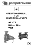
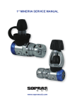
Service Manual
Balanced Diaphragm
First Stage
Copyright 2002, Cressi-sub
Revised 3/2002
○ ○ ○ ○ ○ ○ ○
2
Balanced Diaphragm First Stage Service Manual
Contents
BEFORE STARTING ....................................................................................... 3
DISASSEMBLY ................................................................................................ 3
PARTS CLEANING AND LUBRICATION ....................................................... 7
CLEANING METAL PARTS ............................................................................................ 7
CLEANING COMBINATION METAL/PLASTIC PARTS .................................................. 7
CLEANING PLASTIC-ONLY PARTS .............................................................................. 7
LUBRICATION ................................................................................................................ 7
Types of Lubricant ..................................................................................................... 7
O-rings ....................................................................................................................... 8
Threaded parts .......................................................................................................... 8
REASSEMBLY ................................................................................................. 8
ADJUSTMENT PROCEDURE ....................................................................... 12
FINAL ASSEMBLY AND TESTING ............................................................... 12
TABLE 1 - TROUBLESHOOTING ................................................................. 14
TABLE 2 - REQUIRED TOOLS ..................................................................... 14
EXPLODED PARTS DIAGRAM..................................................................... 15
○ ○ ○ ○ ○ ○ ○
BEFORE STARTING
WARNING
This manual is not a training document. It is meant to be a
guide for experienced technicians who have also received
factory training at a Cressi-sanctioned repair seminar. Do not
attempt to repair this or any regulator without the proper training.
Before starting, Cressi recommends that you read through the entire manual
to familiarize yourself with all the required tools and techniques. Use this
manual as a guide during the servicing process to avoid missing any critical
steps. Make sure the work area is clean and that you work over a cushioned
work surface so critical parts do not get damaged.
Pay close attention to all warnings and cautions as they will alert you to any
potential hazard that may cause damage or injury. Also, pay attention to the
notes as they provide important tips and reminders.
DISASSEMBLY
CAUTION
The following steps require that the first stage be secured in a
vise. Never secure the first stage directly in the vise as it will
damage the body. Instead, thread a vise-mounting tool into one
of the HP ports (located closest to the yoke), and tighten the
mounting tool in the vise. Vise mounting tools are available
from third party accessory companies, or you can use the
following homemade tool: Thread a high-pressure adapter (3/8”
female to 7/16” male) onto an expired CO2 cartridge. Screw the
cartridge into the HP port on the first stage. Mount the CO2
cartridge in the vise. DO NOT thread the CO2 cartridge without
the adapter into a LP port. If the threads of the CO 2 cartridge
break off, it will ruin the first-stage body.
1.
Mount the first stage, adjustment screw facing upward, into
a vise as described in the
caution above (see figure 1).
Using a 6mm hex wrench,
unscrew and remove the adjustment screw (1). Remove the
main spring (3).
Figure 1. Mount first stage in vise and
remove adjustment screw
3
○ ○ ○ ○ ○ ○ ○
4
Balanced Diaphragm First Stage Service Manual
2.
Place the two pins of an adjustable
face spanner wrench into the two
holes in the spring retainer (2) as
shown in figure 2. Rotate counterclockwise and remove. Lift out the
spring pad (4)
Figure 2. Remove spring retainer
CAUTION
DO NOT attempt to pry out the diaphragm. Doing so will
damage the sealing area underneath the diaphragm, causing the regulator to leak when pressurized.
3.
4.
Attach an air nozzle to a low pressure source (25 to 30 psig). If any of
the first stage ports are open, plug
them with spare port plugs, leaving
one of the low pressure (LP) ports
open. Make sure the dust cap (27) is
in place and secured with the yoke
screw. While keeping a finger over
the diaphragm, insert the air nozzle
into the open LP port and add a
quick blast of LP air. The diaphragm
(5) will partially pop out as shown in
figure 3. Completely remove the
diaphragm by lifting it out with your
fingers.
Figure 3. Remove diaphragm with a
short blast of low pressure air
Lift out the pin support (6) and pin (7) as shown in figures 4 & 5.
Figure 4. Remove the pin support
Figure 5. Remove the pin
○ ○ ○ ○ ○ ○ ○
5.
Loosen the vise and turn the regulator so the yoke screw (25) is facing
upward. Tighten the vise so the first stage is secure. Unscrew the yoke
screw from the yoke (23) and remove the dust cap (27) from the yoke
screw. Remove the O-ring (26) located on the outside of the dust cap.
6.
Using a large adjustable wrench or
1 inch wrench, unscrew the yoke retainer
(24), as shown in figure 6, and remove
the yoke (23). Remove the first stage
from the vise and work over the workbench.
Figure 6. Remove yoke retainer
CAUTION
The parts underneath the filter are under spring tension. Keep
pressure applied to the filter when removing the retaining clip
to prevent parts from ejecting from the first stage and causing
injury.
7.
Using needlenose pliers, squeeze the inside “legs” of the retaining clip
(22) while at the same time keeping downward pressure against the filter
(21) as shown in figure 7. Slowly relax the pressure against the filter and
remove the retaining clip. Lift out the spring (20) as shown in figure 8.
Figure 7. Remove filter retaining clip
and filter
Figure 8. Remove balance chamber
spring
5
○ ○ ○ ○ ○ ○ ○
6
Balanced Diaphragm First Stage Service Manual
8.
Turn the first stage over so the balance chamber (19) slides partially
out. Grab it with your fingers and remove it from the first stage (figure
9). If the balance chamber stays inside the first stage, you may gently
grasp it with needlenose pliers and remove it from the first stage.
Using an O-ring tool, remove the O-ring (17) and backup ring (18)
located inside the balance chamber (see figure 10).
Figure 9. Remove balance chamber
9.
Figure 10. Remove O-ring and backup
ring from balance chamber
Turn over the first stage. The high pressure seat assembly (13/14),
spring (15), and balance chamber sleeve (16) will come out as one
assembly (see figure 11). Separate the HP seat and balance chamber
sleeve from the spring. Remove the seat sleeve (14) from the HP seat
(13) as shown in figure 12.
HP Seat
Spring
HP Seat
HP Seat
Sleeve
Figure 11. Remove HP seat assembly
10. Using a 4mm hex wrench, remove
all the port plugs (see figure 13).
Remove the O-ring from each port
plug and discard.
Figure 13. Remove port
plugs with 4mm hex wrench
Balance
Chamber
Sleeve
Figure 12. Separate parts
○ ○ ○ ○ ○ ○ ○
PARTS CLEANING AND LUBRICATION
CLEANING METAL PARTS
1.
Wash all the metal parts in a hot, soapy water solution. Use a soft bristle
toothbrush to clean the threads and remove any flaky corrosion.
2.
After washing in the hot, soapy water, rinse all the parts in fresh water.
3.
Place the metal parts in an ultrasonic cleaner with an appropriate cleaning solution. Avoid using harsh acids such as muriatic acid in ultrasonic
cleaners. Clean the parts for 5 to 15 minutes, depending on the amount
of corrosion.
4.
Remove the parts from the ultrasonic cleaner and rinse them in fresh
water. Blow-dry the parts using low-pressure filtered air.
CLEANING COMBINATION METAL/PLASTIC PARTS
Some parts have plastic and metal molded together, such as the yoke screw
(26). In general, avoid cleaning these parts in an ultrasonic cleaner with an
acidic cleaning solution. Doing so may chemically attack the plastic. The yoke
screw threads may be held in the ultrasonic cleaner, but do not submerge the
plastic yoke knob.
1.
Wash the parts in a hot, soapy water solution. Use a soft bristle toothbrush to clean the threads and remove any flaky corrosion.
2.
After washing in the hot, soapy water, rinse all the parts in fresh water.
3.
Blow-dry the parts using low-pressure filtered air.
CLEANING PLASTIC-ONLY PARTS
Avoid placing plastic parts in an ultrasonic cleaner with an acidic cleaning
solution. To properly clean plastic parts, perform the same steps listed above.
LUBRICATION
Types of Lubricant
Cressi recommends using only food-grade silicone grease or, more preferably, Christo-lube MCG 111.
CAUTION
DO NOT use spray silicones as the aerosol propellants may
chemically attack the rubber compound.
7
○ ○ ○ ○ ○ ○ ○
8
Balanced Diaphragm First Stage Service Manual
O-rings
All O-rings should be treated with a thin film of lubrication. Do not overlubricate the O-rings with large amounts of grease. Simply place a small
amount of grease between your thumb and forefinger and run the O-ring
between them.
Threaded parts
You may lightly lubricate first two threads. As you tighten parts together,
the lubricant will spread to the other threads.
REASSEMBLY
1.
Slide a new HP seat sleeve (14) over a new HP seat (13) as shown in
figure 14. Make sure it is pressed all the way onto the seat (figure 15).
Figure 14. Install sleeve onto HP seat
2.
Figure 15. Make sure sleeve captures
entire plastic disk
Pass the seat spring (15) over the shaft of the HP seat and press it
onto the backside of the seat sleeve (figure 16). Press the balance
chamber sleeve (16) into the other end of the spring (figure 17). Insert
this assembly into the first stage body, HP seat first, as shown in
figure 18.
Figure 16. Install seat spring
Figure 17. Press balance
chamber sleeve into spring
Figure 18. Install assembly
into first stage body
○ ○ ○ ○ ○ ○ ○
3.
Install a new backup ring (18) and lubricated O-ring (17) into the balance
chamber (19) as shown in figures 19 & 20. Insert the balance chamber
assembly into the balance chamber sleeve as shown in figure 21.
Figure 19. Install backup
ring
4.
Figure 20. Install O-ring
Place the balance spring (20) onto the balance chamber (figure 22). Set
the filter (21) on top of the spring with the cup of the filter facing upward
as shown in figure 23.
Figure 22. Install balance spring on top
of balance chamber
5.
Figure 21. Install balance
chamber into sleeve.
Figure 23. Place filter, cup facing
upward, onto spring
Grasp the inner “legs” of the retaining clip (22) with needlenose pliers
and squeeze the legs together. Align the outer edges of the retaining clip
and filter. Press down on the filter with the tips of the needlenose pliers to
compress the springs (figure 24). It may be necessary to press one side
of the retaining clip into the first stage using your finger or a small dowel.
When the retaining clip is in place, release the pressure on the needlenose pliers. Inspect the retaining clip to make sure it is properly seated
all the way around the groove (figure 25).
Press down
on clip if
necessary
Figure 24. Install filter retaining clip
Figure 25. Inspect retaining clip to make
sure it is properly seated
9
○ ○ ○ ○ ○ ○ ○
10
Balanced Diaphragm First Stage Service Manual
6.
Turn the regulator over. Insert the pin (7) into the small hole located in
the center of the first stage body (figure 26). Place the pin support (6)
onto the pin (figure 27). Press the pin support a few times. It should
have a smooth, springy feel.
Pin
Figure 26. Install pin
7.
Press a new diaphragm (5) into the first stage. Using your finger, work
the edges of the diaphragm into place so it is evenly seated in the
groove below the threads (figure 28). Place the spring pad (4) in the
middle of the diaphragm (figure 29) and place the main spring (3)
onto the spring pad (figure 30).
Figure 28. Install
diaphragm
8.
Figure 27. Install pin support
Figure 29. Place spring pad
in center of diaphragm
Figure 30. Place main
spring onto spring pad
Thread the spring retainer (2) onto the first stage body until handtight
(figure 31). Thread the adjustment screw (1) into the spring retainer
and tighten using a 6mm hex wrench (figure 32). Tighten the adjustment screw until it is flush with the end of the spring retainer.
Figure 31. Thread spring retainer onto
body until handtight
Figure 32. Screw in adjustment screw
until flush with spring retainer
○ ○ ○ ○ ○ ○ ○
9.
Place the yoke (23) over the first stage inlet (figure 33). Thread the retaining nut (24), wrench flats facing upward, onto the first stage inlet until
hand tight (figure 34).
Figure 33. Place yoke onto first stage
body
Figure 34. Thread yoke retainer onto inlet
boss
10. Thread the vise mounting tool back
into one of the high pressure ports.
Mount the first stage into a vise with
the yoke facing upward. Attach a
1 inch crows-foot to a torque wrench.
Tighten the retaining nut to 20 footpounds (figure 35).
Figure 35. Tighten retainer to 20 footpounds
11. Loosen the vise and turn the
regulator over so the spring retainer is facing upward. Using the
adjustable face spanner wrench,
tighten the spring retainer until it
stops (figure 36).
Figure 36. Tighten spring retainer with
adjustable face spanner wrench until it
stops
11
○ ○ ○ ○ ○ ○ ○
12
Balanced Diaphragm First Stage Service Manual
12. Place a new o-ring (26) onto the dust cap (27). Pass the loop of the
dust cap over the yoke screw threads. Thread the yoke screw into the
yoke.
ADJUSTMENT PROCEDURE
1.
Install new O-rings (8 & 11) on the LP and HP port plugs. Install only
two LP port plugs and both HP port plugs. Leave the other two LP
ports open for the testing procedure to follow.
2.
Attach a second stage to one of the open LP ports. This will act as an
over pressure valve in case of a high-pressure leak. Attach a LP test
gauge (0-400 psi) to the other open LP port. (Note: A test gauge with
a relief valve is highly recommended.)
3.
Attach the first stage to a fully charged cylinder (2500 to 3000 psi).
Crack open the relief valve on the test gauge and slowly open the
cylinder valve. After the cylinder valve is fully open, close the test
gauge relief valve. The intermediate pressure (IP) should be 140±5
psi.
4.
If the IP does not fall within this range, use a 6mm hex wrench to turn
the adjustment screw (22) and adjust the IP. Turning clockwise increases IP, turning counterclockwise decreases IP. After making an
adjustment, cycle the regulator by purging the second stage several
times and reread the IP. After IP is set, continue to observe it to make
sure IP remains constant.
FINAL ASSEMBLY AND TESTING
1.
Close the cylinder valve and purge the air from the regulator system.
Remove the first stage from the cylinder and remove the second
stage and test pressure gauge, and the port plugs if necessary.
2.
Install the customer’s second stages, inflator hose(s) and pressure
gauge back into the first stage, using the same configuration as when
you received the regulator in for service.
3.
Reattach the first stage to the cylinder and slowly open the cylinder
valve to pressurize the regulator. Dip the entire first stage into a water
bath and watch for leaks. Any streaming bubbles means there is a
leak somewhere. Note the location of the leak and refer to the troubleshooting guide for possible remedies. If there are no leaks, close the
cylinder valve, purge the regulator, and remove from the valve.
○ ○ ○ ○ ○ ○ ○
4.
Dry off the first stage. Blow out any moisture in the dust cap with lowpressure air. Place the dust cap over the inlet fitting and tighten the yoke
screw to secure the dust cap in place.
13
○ ○ ○ ○ ○ ○ ○
14
Balanced Diaphragm First Stage Service Manual
TABLE 1 - TROUBLESHOOTING
Problem
Cause
Solution
Air leak from spring retainer
a. Spring retainer (2) not tight
b. Diaphragm sealing area damaged
c. Diaphragm (5) worn or damaged
a. Tighten spring retainer
b. Replace body (12)
c. Replace diaphragm
I.P. Creep
a. HP seat (13) worn or damaged
b. HP seat sealing surface damaged
c. O-ring (17) worn or damaged
d. Backup ring (18) worn or damaged
e. Balance chamber scratched internally
a. Replace HP seat
b. Replace body (12)
c. Replace O-ring
d. Replace backup ring
e. Replace balance chamber (19)
TABLE 2 - REQUIRED TOOLS
Tool Description
1.
One inch open end wrench
2.
Needlenose pliers
3.
O-ring tool
4.
Adjustable spanner wrench
5.
3/8”-7/16” vise mounting tool
6.
4mm hex wrench
7.
6mm hex wrench
8.
Torque Wrench
9.
1-inch crows-foot
Used for
Removing yoke retainer (24)
Removing filter retaining clip (22)
Removing O-rings
Removing/installing spring retainer (2)
Mounting first stage into vise
Removing/installing all port plugs
Removing/installing adjustment screw (1)
Tightening yoke retainer (24)
Used with torque wrench
○ ○ ○ ○ ○ ○ ○
EXPLODED PARTS DIAGRAM
25
27
26
23
22
20
18
16
15
14
21
24
13
12
19
17
6
11
5
4
10
3
7
8
2
1
9
Key # Description
1.
Adjustment Screw
Key # Description
16.
Sleeve, Balance Chamber
2.
Spring Retainer
17.
O-ring
3.
Main Spring
18.
Backup Ring
4.
Spring Pad
19.
Balance Chamber
5.
Diaphragm
20.
Spring, Balance Chamber
6.
Pin Support
21.
Filter
7.
Pin
22.
Retaining Clip
8.
O-ring, LP Port (x3)
23.
Yoke
9.
Port Plug, LP (x3)
24.
Yoke Retainer
10.
Port Plug, HP (x2)
25.
Yoke Screw
11.
O-ring, HP Port (x2)
26.
O-ring
12.
Body
27.
Dust Cap
13.
HP Seat
29.
O-ring
14.
Sleeve, HP seat
30.
Filter
15.
Spring, HP seat
Parts in bold are to replaced
during each overhaul
15
PROFESSIONAL UNDERWATER EQUIPMENT
1 Charles Street, Westwood, NJ 07675
Tel: 800-338-9143 Fax: 800-493-2680