1
AAON
®
RM SERIES
HEATING • COOLING & COMBINATION
ROOFTOP UNITS
USERS
INFORMATION
MANUAL
7-2003
! WARNING
▲
FOR YOUR SAFETY
WHAT TO DO IF YOU SMELL GAS
• EXTINGUISH ANY OPEN FLAME.
If the information in this manual is not followed
exactly, a fire or explosion may result causing
property damage, personal injury or loss of life.
• DO NOT TOUCH ANY ELECTRICAL SWITCH.
• DO NOT TRY TO LIGHT ANY APPLIANCE.
• DO NOT USE ANY PHONE IN YOUR BUILDING.
FOR YOUR SAFETY
• IMMEDIATELY CALL YOUR GAS SUPPLIER FROM A
NEIGHBOR'S PHONE.
FOLLOW THE GAS SUPPLIER'S INSTRUCTIONS.
DO NOT STORE OR USE GASOLINE OR OTHER
FLAMMABLE VAPORS AND LIQUIDS IN THE
VICINITY OF THIS OR ANY OTHER APPLIANCE.
• IF YOU CANNOT REACH YOUR GAS SUPPLIER,
CALL THE FIRE DEPARTMENT.
1
AAON®
TABLE OF CONTENTS
SECTION
PAGE NUMBER
OWNER'S INFORMATION ………………………………………………………………………………3 - 4
HEATING / COOLING SYSTEMS …………………………………………………………………… 4 - 5
Gas Unit Lighting Instructions
PERIODIC INSPECTION PROCEDURES…………………………………………………………… 6 - 7
SERVICE, TROUBLE SHOOTING & MAINTENANCE …………………………………………… 8
Lubrication
Cleaning
FILTER INSTALLATION / REPLACEMENT ……………………………………………………… 9
SERVICING …………………………………………………………………………………………… 10 - 12
Rooftop Unit Replacement Parts
SEQUENCE OF OPERATIONS ……………………………………………………………………… 13
Heating
Cooling
Optional Economizer
VAV Systems …………………………………………………………………………………… 14
Power Exhaust Options
! IMPORTANT
▲
! WARNING
▲
The Clean Air Act of 1990 bans the
intentional venting of refrigerant (CFC's and
HCFC's) as of July 1, 1992. Approved
methods of recovery, recycling or reclaiming
must be followed. Fines and/or incarceration
may be levied for non-compliance.
Improper installation, adjustment, alteration,
service or maintenance can cause property
damage, personal injury or loss of life.
Installation and service must be performed
by a qualified installer, service agency
or the gas supplier.
Owner should pay particular attention to the words: NOTE, CAUTION AND WARNING.
NOTES are intended to clarify or make the installation easier. CAUTIONS are given to prevent
equipment damage. WARNINGS are given to alert owner that personal injury and/or equipment damage
may result if installation procedure is not handled properly.
It is the intent of AAON, Inc. to provide accurate and current specification information. However, in the interest of product improvement,
AAON, Inc. reserves the right to change pricing, specifications and/or design of it's products without notice, obligation or liablity.
R15700 (7-03)
© 2003 AAON, Inc., all rights reserved throughout the world.
AAON & AAONAIRE are registered trademarks of AAON, Inc., Tulsa, OK.
2
OWNER'S INFORMATION
The units are designed as self-contained heating, cooling
or combination units for outdoor installation only, using
the refrigerant shown on the rating plate, chilled water,
natural or propane gas, electric resistance, steam or hot
water heating.
!
▲
WARNING
Electric shock hazard. Can cause injury or
death. Before attempting to perform any
service or maintenance, turn the electrical
power to unit to OFF at disconnect switch(es).
Unit may have multiple power supplies.
WARNING
Failure to observe the following instructions will result
in premature failure of your system, and possible voiding of the warranty.
DIRECT EXPANSION (DX) COOLING UNITS
Never cut off the main power supply to the unit, except
for complete shutdown. When power is cut off from the
unit, compressors with crankcase heaters cannot prevent refrigerant migration. The compressor will cool
down, and liquid refrigerant will accumulate in the
compressor. The compressor is designed to pump only
refrigerant gas and damage may occur when power is
restored.
If power must be cut off for more than an hour, turn the
thermostat system switch to "OFF", and leave it off until
the main power switch has been turned on again for at
least twenty four hours on units with compressor crankcase heaters. This will give the crankcase heater time to
clear liquid accumulation out of the compressor before it
is required to run.
Always control the system from the thermostat, or control panel, never at the main power supply (except in an
emergency or complete shutdown of the system).
AIRFLOW IS TO BE ADJUSTED AFTER
INSTALLATION TO OBTAIN AN AIR
TEMPERATURE RISE WITHIN THE RANGE
SPECIFIED ON THE RATING PLATE.
DUE TO JOB SPECIFICATION REVISIONS,
IT MAY BE NECESSARY TO ADJUST OR
CHANGE THE SHEAVE OR PULLEY TO
OBTAIN THE DESIRED AIRFLOW
AT THE TIME OF INSTALLATION.
▲! CAUTION
START-UP TECHNICIAN MUST CHECK BLOWER
MOTOR AMPERAGE TO ENSURE THAT THE
AMPERAGE LISTED ON THE MOTOR NAMEPLATE
IS NOT EXCEEDED.
CAUTION: While the following incorrect operations
may not cause damage to the system, they will impair
the performance, and may cause the built-in safety
devices to cut the system off completely.
During the cooling season, if the air flow is reduced due
to dirty air filters or other reasons, the cooling coils will
get too cold and result in excessive liquid return to the
compressor. As the liquid concentration accumulates,
oil is washed out of the compressor, leaving it starved for
lubrication.
The compressors must be on a minimum of 4 minutes
and off for a minimum of 5 minutes. The cycle rate must
not exceed 8 starts per hour.
1. LOW AMBIENT OPERATION
The cooling section of a direct expansion (DX) unit
will not operate properly when the outdoor temperature is below 55°F. Outside air intake options are
necessary if operation below 55°F is expected.
2. MULTIPLE UNIT OPERATION
When several units are used in conditioning the
space, and any are combination heating-cooling
units, all system thermostat switches must be set at
either heating, cooling, or set at "off". Do not run
part of a system switched to an opposite mode.
Cooling only units should be switched to "off" at the
thermostat during the heating season.
THE COMPRESSOR LIFE WILL BE SERIOUSLY
SHORTENED BY RESULTING REDUCED LUBRICATION, AND THE PUMPING OF EXCESS AMOUNTS
OF LIQUID OIL AND REFRIGERANT.
GAS OR ELECTRIC HEATING
The system is designed to heat a given amount of air each
minute it operates. If the amount of air heated is greatly
reduced (approximately 1/3 capacity), the heat exchanger / heater coil temperature will increase above
acceptable level and result in shut down by a high
temperature safety switch incorporated either in the
heat exchanger or the heater area.
WIRING DIAGRAMS
A complete set of unit specific wiring diagrams in both
ladder and point-to-point form are laminated in plastic
and located inside the control compartment door.
GAS HEAT UNITS - WARNING: If, due to safety switch
shut off or gas supply shut off failure; ALWAYS CLOSE
MANUAL GAS VALVE TO UNIT PRIOR TO ANY
ELECTRICAL SERVICE.
PROLONGED OVERHEATING OF THE HEAT
EXCHANGER WILL SHORTEN ITS LIFE.
3
CONDENSATE PIPING
A drain trap is to be connected to the drainpan. If codes
require a condensate drain line, it should be the same
pipe size as the drain nipple and should pitch downward
toward drain.
The condensate drain pipe ("P" trap) is factory supplied
and shipped in the control access compartment for field
installation. An air break should be used with long runs
of condensate lines.
OWNERS INFORMATION continued
!
IMPORTANT NOTICE:
All gas-fired heat exchangers are completely tested at
the factory before shipment. This will remove nearly all
of the oils that have been used in the manufacturing
process, however, trace amounts may remain. When
performing the initial start-up at the jobsite, it is highly
recommended that people or any other living animals,
that may be sensitive to the residual odors or gases, NOT
be present in the conditioned space during the start-up.
In all cases, including the initial factory firing and
testing, any of the gases will be under the acceptable
level of concentration for human occupancy.
WARNING
Those sensitive to odors or gases from
trace amounts of residual oils
should NOT be present in the
conditioned space during the start-up
of a gas-fired installation.
NOTE: In case emergency shut down is required, turn
off the main manual gas shut-off valve and disconnect
main electrical power to unit. These devices should be
properly labeled by the installer.
HEATING & COOLING SYSTEMS
NORMAL OPERATION
GAS HEATING SYSTEM
The heating section is for use with natural gas supply
pressure of 6" to 10.5" Water Column. The unit may also
utilize propane gas with a supply pressure to the valve
of 11" to 12" Water Column. The rating plate on the
furnace must be inspected to make sure the unit is
stamped for proper gas. A 1/8" pressure tap should be
field supplied by the installer in the piping just ahead of
the gas valve. The pressure tap on the outlet end of the
gas valve can be checked to verify manifold pressure of
3.2" to 3.5" for natural gas.
Combustion air is supplied by a centrifugal blower
which draws in outside air through a protected opening.
This induced draft blower introduces the air to the
burner tubes which assures even primary and secondary
air flow.
All heating system and related safety controls are 100%
tested on each unit prior to shipment.
HEATING
Set the thermostat system switch to "HEAT".
Set the thermostat fan switch to "AUTO" or "ON".
Set the thermostat temperature at the desired point.
COOLING
Set the thermostat system switch to "COOL".
Set the thermostat fan switch to "AUTO" or "ON".
Set the thermostat temperature at the desired point.
AIR CIRCULATION
Set the thermostat system switch to "OFF".
Set the thermostat fan switch to "ON".
Do not change temperature setting.
With these settings, the air circulating blower will run
continuously but the air will not be heated or cooled.
SYSTEM OFF
Set the thermostat system switch to "OFF".
Set the thermostat fan switch to "AUTO".
Do not change temperature setting.
With these settings, the system is shut down, with the
exception of the control system power (24 Vac), and the
crankcase heater of the compressor (approx. 60W).
The units are equipped with a direct spark ignition
system which proves the burner operation during each
call for heat. Power to the ignition control is 24 Vac to
reduce hazards. Burner ignition is by a high intensity
spark.
When heat is called for, the cooling system is inoperable
except for the indoor blower motor. Heating is accomplished by firing gas into the heat exchanger assembly.
DO NOT TURN OFF THE MAIN POWER SWITCH.
NIGHT AND VACANT WEEKEND OPERATION
To reduce the operation time during low load periods,
it is recommended that the temperature setting be
increased five degrees during these periods of the cooling
season, and decreased ten degrees during the heating
season.
4
GAS UNIT LIGHTING INSTRUCTIONS
FOR YOUR SAFETY READ BEFORE OPERATING
WARNING: IF YOU DO NOT FOLLOW THESE INSTRUCTIONS EXACTLY, A FIRE OR EXPLOSION MAY
RESULT CAUSING PROPERTY DAMAGE, PERSONAL INJURY OR LOSS OF LIFE.
A.
B.
•
•
•
This appliance does not have a pilot. It is equipped with an
ignition device which automatically lights the burner.
Do not try to light the pilot by hand.
•
If you cannot reach your gas supplier, call the fire department.
C.
Use only your hand to push in or turn the gas control knob.
Never use tools. If the knob will not push in or turn by hand,
don't try to repair it, call a qualified service technician. Force
or attempted repair may result in a fire or explosion.
D.
Do not use this appliance if any part has been under water.
Immediately call a qualified service technician to inspect the
appliance and to replace any part of the control system and
any gas control which has been under water.
BEFORE OPERATING smell all around the appliance area
for gas. Be sure to smell next to the floor because some gas
is heavier than air and will settle on the floor.
WHAT TO DO IF YOU SMELL GAS
Do not try to light any appliance.
Do not touch any electric switch; do not use any phone
in your building.
Immediately call your gas supplier from a neighbor's phone.
Follow the gas supplier's instructions.
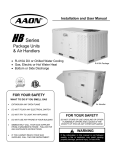
OPERATING INSTRUCTIONS
1.
STOP! Read the safety information above this label.
5.
Open control access panel.
2.
Set the thermostat to lowest setting.
6.
3.
Turn off all electric power to the appliance.
Push in gas control knob slightly and turn clockwise
to "OFF".
NOTE: Knob cannot be turned to "OFF" unless knob is pushed
in slightly. Do not force.
4.
This appliance is equipped with an ignition device which
automatically lights the burner. Do not try to light the pilot by
hand.
7.
WAIT five (5) minutes to clear out any gas. Then smell for gas, including
near the floor. If you smell gas, STOP! Follow "B" in the safety
information above on this label. If you don't smell gas, go to the next step.
8.
Turn gas control knob counterclockwise
GAS CONTROL KNOB
SHOWN IN "ON"
POSITION
GAS INLET
ON
OFF
to "ON".
9.
Close control access panel.
10.
Turn on all electric power to the appliance.
11.
Set thermostat to desired setting.
12.
If the appliance will not operate, follow the instructions
"To Turn Off Gas To Appliance" and call your service
technician or gas supplier.
TO TURN OFF GAS TO APPLIANCE
1.
Set the thermostat to lowest setting.
4.
Push in gas control knob slightly and turn clockwise
"OFF". Do not force.
2.
Turn off all electric power to the appliance if service
is to be performed.
5.
Close control access panel.
3.
Open control access panel.
to
The air cooled condenser coil(s) are constructed of copper
tubes and mechanically bonded aluminum fins and air
pulled through by propeller fans. The evaporator coil is
draw through type constructed of copper tubes and
mechanically bonded aluminum fins.
ELECTRIC HEATING SYSTEM
Heating is accomplished by passing electrical current
through a specified amount of resistance heaters which
produce the required heat. The indoor blower motor
energizes at the same time as the heaters.
The refrigeration section of these appliances has been
found acceptable with applicable provisions of "ANSI /
UL 1995" and current "C.S.A. Standard C22.2" by E.T.L.
STEAM OR HOT WATER HEATING SYSTEM
Heating is accomplished by passing steam or hot water
through the steam or hot water coil assembly.
NOTE: Crankcase Heater Operation
Some units are equipped with a compressor crankcase
heater, which should be energized at least 24 hours prior
to setting the thermostat for cooling operation.
COOLING SECTION • DX
All direct expansion refrigeration systems are factory
assembled, charged with refrigerant, tested and operated. On all units 8 ton and larger the refrigerant
system includes multiple circuit evaporator and condenser coils providing two or more stages of cooling.
These systems are provided with liquid line filter driers,
expansion valves and fully hermetic compressors.
Compressors are equipped with a positive pressure
forced lubrication system.
5
COOLING SECTION • CHILLED WATER
or NON-COMPRESSORIZED UNIT
Chilled water or non-compressorized units have factory
installed coils. Systems are provided with internal
header connections for field piping. Coils are constructed of copper tubes and mechanically bonded aluminum fins.
PERIODIC INSPECTION PROCEDURES
GAS HEATING UNITS
1.
The flow of combustion and ventilating cannot
be obstructed in any way. The indoor blower, evaporator
coil and filters must be inspected monthly.
2.
Once each year, prior to the heating season, a
qualified technician must inspect all flue product carrying areas of the furnace and main burners for continued
safe operation.
WARNING:
At least once each year, a qualified service technician should check out all of the items listed
under the servicing and trouble shooting and maintenance section of this manual.
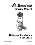
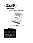
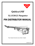
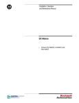
Heat Exchanger prior to installation in unit.
Note dimple construction.
3.
If the induced draft blower/motor assembly requires replacement, an airtight seal between the blower
housing and the burner box must be restored. High
temperature silicone sealant must be used to ensure a
good seal.
4.
GAS BURNERS
THE BURNERS SHOULD NEVER REQUIRE
CLEANING.
If cleaning is necessary, it indicates faulty operation of
the unit. The cleaning should be done only by a qualified
service agency after consultation with an AAON Service
Representative.
It is recommended that if the gas burners require cleaning,
call an AAON Service Engineer at (918) 583-2266.
5.
HEAT EXCHANGER
The necessity for cleaning the exchanger could indicate
faulty operation and should only be checked by a qualified service agency after they have discussed the problem with a Service Representative.
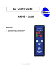
Combustion Motor
Burner Assembly
Flame Sensor
Burner
Horn (typ)
Manifold
Spark Rod
6
Flue Outlet
PERIODIC INSPECTION PROCEDURES Continued
!
▲
WARNING
HEATING • ELECTRIC
1. Set thermostat in the heat mode.
Electric shock hazard. Can cause injury or
death. Before attempting to perform any
service or maintenance, turn the electrical
power to unit to OFF at disconnect switch(es).
Unit may have multiple power supplies.
2. Set thermostat to call for heat to engage all electric
heat strips. Check blower for proper rotation and
voltage.
3. Measure the amperage and voltage. Compare them
to the nameplate data.
COOLING
1. Main Power Switches are on and power is to the unit.
HEATING • STEAM OR HOT WATER
1. Set thermostat in the heat mode.
2. Set thermostat in cooling mode and place the "fan"
switch to on. Check blower for correct operating
direction, amperage and voltage.
2. Check supply blower for proper rotation and voltage.
3. Check boiler or hot water operations according to the
manufacturer's instructions and recommendations.
3. PACKAGED UNITS - Check compressor(s)
operation. Check the amperage and compare to the
nameplate data (check amperage load side of the
compressor contactor).
4. Check control flow valves for correct operation and
settings according to the manufacturer's instructions and recommendations.
4. DX COIL UNITS - If applicable check remote condenser as per the manufacturer's recommendations.
ELECTRIC, STEAM, HOT WATER, COOLING &
CHILLED WATER UNITS
5. CHILLED WATER UNITS - Check remote chiller
operations as per the manufacturers instructions.
Check coolant flow valves for correct operation and
settings.
1. Blower, coils and filters should be inspected monthly.
2. Once a year, before unit is turned on for the heating
season, a qualified service technician should inspect
the unit for proper operation.
HEATING • NATURAL GAS
1. Before turning on the main electrical power switch,
be sure that all gas supply lines have been purged of
air.
3. All valves and steam traps should be inspected
according to the manufacturer's instructions and
recommendations.
2. Turn gas valve to "ON" position.
3. Turn main electrical power switch to "ON" and set
the thermostat to call for heat. The vent motor
should operate. The control will automatically
supply energy to the spark gap and the gas valve
after the thermostat contact closes.
WARNING: All of the items listed under the service,
trouble shooting and maintenance section of this manual
should be performed once a year.
4. The sensing probe detects the presence of the flame.
(Should no flame be detected in 10 seconds, the
ignition system will recycle. If no flame is detected
in 3 tries, the ignition system will lockout.)
5. Adjust thermostat to a low temperature setting to
open contacts. The main gas flames should be
extinguished.
NOTE: The evaporator blower is controlled by the
ignition system. In the fan "Auto" mode the blower
comes on 45 seconds after flame is proved and goes off
120 seconds after the thermostat opens.
7
SERVICING, TROUBLE SHOOTING & MAINTENANCE
!
▲
LUBRICATION
All original blower motors and bearings are furnished
with an orginal factory charge of lubrication. Some
applications will require that bearings be re-lubricated
periodically. The schedule will depend on the operating
duty, temperature variations or other harsh atmospheric
conditions.
WARNING
ELECTRIC SHOCK HAZARD.
Shut off all electrical power to unit to avoid
shock hazard or injury from rotating parts.
Bearings should be re-lubricated when at normal operating temperatures, but not during operation. Rotate
the fan shaft manually and add minimum lubricant
required to purge the seals. DO NOT OVERLUBRICATE.
CLEANING
Inspect unit interior at the beginning of each heating
and cooling season and as operating conditions require.
COILS
Evaporator coil(s) should be inspected and cleaned annually to ensure there is no obstruction to air flow.
Recommended lubricants are:
SHELL OIL - DOLIUM R
CHEVRON OIL - SRI No. 2
TEXACO INC. - PREMIUM RB
Condenser coil(s) should be inspected monthly. Clean
condenser coils annually or as required by location and
outdoor air conditions.
SERVICE
If the unit does not function properly and service is
required, service technicians qualified and experienced
in both gas, electric heating and air conditioning are
permitted to provide service to keep warranties in effect.
The service technician should call the factory if assistance is required.
CONDENSATE DRAIN
Check and clean annually at start of cooling season.
BLOWER
Inspect blower and blower section to keep free of dust or
debris.
SERVICE TECHNICIAN MUST PROVIDE THE
MODEL AND SERIAL NUMBER OF THE SPECIFIC
UNIT TO CUSTOMER SERVICE TO ASSURE A CORRECT DIAGNOSIS.
TURN OFF POWER BEFORE ATTEMPTING TO
CLEAN BLOWER WHEEL.
AAON, Inc.
Phone: 918-583-2266
Fax:
918-382-6364
Customer Service Department
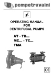
COMMON CAUSES OF REDUCED AIR FLOW
A.
DIRTY FILTERS - Filters must be inspected and
replaced on a regular basis. It is strongly recommended
that the media be replaced monthly. Clean filters are
your best protection against premature system breakdown.
Do not operate the unit without the filters in place.
Operation of the unit without filters will result in a
clogged evaporator coil - a very expensive service problem to resolve.
B.
OBSTRUCTION TO AIR FLOW - Supply and
return air grilles must be kept clear so air can be freely
discharged from and drawn into the system.
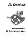
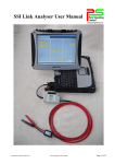
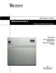
Typical slide-out blower section
8
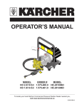
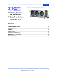
FILTER INSTALLATION / REPLACEMENT
!
▲
Before inspecting or replacing the filters, be sure the
unit IS NOT operating. The filters are located in the
filter access section of the unit. Open filter access door,
and pull filters straight out to inspect. Inspect ALL
filters each time. Replace filters with the size indicated
on each filter or as shown in the filter chart below. Arrow
on replacement filters must point towards the blower.
Monthly inspection is required to maintain optimum
efficiency.
WARNING
Before attempting to perform any service
or maintenance, turn the electrical power
to unit to OFF at disconnect switch(es).
Unit may have multiple power supplies.
IT IS IMPORTANT TO KEEP COILS, BLOWER AND FILTERS CLEAN !
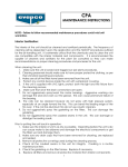
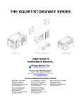
Slide-out
filters
Optional
Economizer
Optional R/A
smoke detector
location
NOTE: CHART REFLECTS STANDARD FACTORY SUPPLIED FILTERS AND SIZES.
CONTACT FACTORY FOR SPECIAL OPTIONAL FILTER PACKAGES.
FILTERS
FILTER SIZE
16" x 20"
Standard 2" Throwaway
16" x 20"
Optional 2" or 4" Pleated
2 -5
6&7
4
4
4
UNIT SIZE
8 & 10
13 & 15
6
6
16 - 30
6
20" x 25"
6
Optional 2" or 4" Pleated
FILTERS SHOULD BE REPLACED EVERY 30 DAYS OR AS REQUIRED.
9
SERVICING
POSSIBLE CAUSE
TROUBLE
ELECTRIC HEATING
SYSTEM OFF
1. Check power at line side of contactor(s).
2. Thermostat not set for heating.
EVAPORATOR MOTOR WILL NOT RUN
1. Overload relay tripped.
2. Heater Relay not energized.
3. Blower Contactor not energized.
4. Capacitor shorted or open (PSC motors only).
BLOWER DOESN'T DELIVER AIR
1. Blower running backwards.
2. Dirty air filters.
3. Dirty coils.
4. Duct obstruction.
5. Belts loose (if applicable).
BLOWER COMES ON, BUT LITTLE OR NO
HEAT
1. One or more heater contactors are open.
2. Limit switches are open.
3. Heater relay open.
4. Heat strips burned out.
GAS HEATING
SYSTEM OFF
1. Check power and gas supply.
2. Check thermostat switches and settings.
3. Check 24 volt power to ignition control.
BURNER WON'T COME ON
1. Check for power at main gas valve.
2. Defective gas valve.
3. Loose or broken connection to gas valve.
4. Check limit controls for open.
5. Check continuity of differential pressure switch with motor
turning. If open, replace differential pressure switch.
6. Defective ignition control.
COMBUSTION AIR BLOWER WON'T RUN
1. Thermostat not calling for heat.
2. Relay not closing. (No power to motor)
3. Motor stuck or winding open.
4. Internal motor overload open.
BURNER GOES "OFF" ON HIGH LIMIT
1. Unit blower not coming on. (Check fan control)
2. Blower motor running backward.
3. Filters dirty.
4. Ducts obstructed or dampers closed.
5. Manifold gas pressure too high.
IGNITION ON, BURNER WON'T LIGHT
1. Hand valve "off" (turn to on)(main gas valve).
2. Gas off or very low pressure.
3. Check for power at main gas valve.
4. Check continuity of differential pressure switch with motor
turning. If open, replace differential pressure switch.
5. Sparker sensor out of adjustment.
6. Main orifice blocked.
SUPPLY FAN BLOWER WON'T RUN
1. Defective Ignition Control.
2. Refer to cooling trouble shooting page.
10
SERVICING Continued
POSSIBLE CAUSE
TROUBLE
STEAM AND HOT WATER HEATING
SYSTEM OFF
1. Check power at line side of contactor(s).
2. Thermostat not set for heating.
BLOWER MOTOR WILL NOT RUN
1. Overload relay tripped.
2. Heater Relay not energized.
3. Blower Contactor not energized.
BLOWER DOESN'T DELIVER AIR
1. Blower running backwards.
2. Dirty air filters.
3. Dirty coils.
4. Duct obstruction.
5. Belts loose (if applicable).
1. Check steam traps, valves, and steam or hot water
supply in accordance with manufactures instructions.
BLOWER COMES ON, BUT LITTLE OR NO HEAT
2. Faulty thermostat.
COOLING PACKAGE and UNITS with REMOTE CONDENSERS
SYSTEM OFF
1. Check power at lineside of contactor(s).
2. Thermostat not set for cooling.
3. High pressure control tripped.
4. Low pressure switch open (loss of charge).
CONDENSER FAN WILL NOT RUN
1. Overload thermal protector open in motor.
REFER TO MFG'S
2. Motor run capacitor open or shorted.
INSTRUCTIONS
3. Motor failed.
IF REMOTE
CONDENSER
4. Fan or shaft stuck.
EVAPORATOR BLOWER WILL NOT RUN
1. Overload thermal protector open in motor.
2. Relay not closing.
3. Motor failed.
4. Capacitor shorted or open (PSC motors only).
5. Stuck shaft or blower wheel.
COMPRESSOR SHORT CYCLES
1. Check for low refrigeration charge.
2. Compressor overload setting.
3. Ambient temperature too low.
4. Filters dirty or air flow restricted.
5. Evaporator blower not running.
FAN MOTOR RUNS HOT AND CUTS OUT
1. Line voltage too high.
COMPRESSOR WILL NOT START
1. Line voltage too low.
2. Limit switches are open.
3. Overload or pressure control tripped.
BLOWER DOES NOT DELIVER AIR
1. Blower running backwards.
2. Dirty filters.
3. Duct obstruction.
4. Belts loose (if applicable).
11
REFER TO MFG'S
INSTRUCTIONS
IF REMOTE
CONDENSER
REFER TO MFG'S
INSTRUCTIONS
IF REMOTE
CONDENSER
SERVICING Continued
POSSIBLE CAUSE
TROUBLE
COOLING - CHILLED WATER
SYSTEM OFF
1. Check power at line side of contactor(s).
2. Thermostat not set for cooling.
EVAPORATOR BLOWER WILL NOT RUN
1. Overload thermal protector open in motor.
2. Contactor not closing.
3. Motor failed.
FAN MOTOR RUNS HOT AND CUTS OUT
1. Line voltage too high.
BLOWER DOES NOT DELIVER AIR
1. Blower running backwards.
2. Dirty air filters.
3. Duct obstruction.
4. Belt loose (if applicable).
BLOWER COMES ON, BUT LITTLE OR NO
COOLING
1. Check supply water and temperature.
2. Check water control valves operation.
3. Check water temperature rise entering and leaving
unit to determine if adequate water is flowing.
ROOFTOP UNIT REPLACEMENT PARTS
Replacement parts for AAON equipment may be obtained from AAON. When ordering parts, always reference the
unit model number, serial number and part number.
AAON, Inc.
Customer Service Department
2425 South Yukon Ave • Tulsa, Oklahoma 74107
Phone: 918-583-2266 • Fax: 918-382-6364
ALWAYS USE AAON SPECIFIED PARTS
12
SEQUENCE OF OPERATIONS
I.
GENERAL INFORMATION
A.
HEATING
B.
1.
Natural Gas
When the thermostat calls for heating, W1 makes R to
the heat relay (HR). All N.O. (Normally open) contacts
close and all N.C. (normally closed) contacts open. The
combustion motor starts and as the pressure decreases in
the flue outlet box the ignition control is energized. The
control sends 24 VAC to the main gas valve and high
voltage to the ignitor. If a burner flame has been detected
after 10 seconds, the spark is extinguished and the flame
continues. If a flame has not been detected after 10
seconds, the gas valve closes, the spark ceases and the
induced draft blower continues to purge the heat exchanger. After 45 seconds of purge, the ignition system
will attempt to light the burners again. Should no flame
be detected after 3 attempts, the ignition control locks out
the system.
COOLING
1.
Packaged Units
When the thermostat calls for cooling from the space, 'Y1'
makes 'R' to 'CC1' through the LPS (low pressure switch),
HPS (high pressure switch) and optional GOT (guarantee off timer).
2.
DX Only - Coil Units
When the thermostat calls for cooling from the space, the
condensing unit is energized (refer to manufacturers
instructions for sequence of operation). The evaporator
blower contactor is energized simultaneously with the
condensing section.
3.
Chilled Water Coil Units
The blower contactor is energized to provide supply air on
a signal from the space thermostat. All other controls are
by others.
On a fault the gas train is shut down by a main limit
located in the heat exchanger area or by an auxiliary
limit mounted in the supply air fan housing.
C.
OPTIONAL ECONOMIZER
When cooling is called for and the unit has the economizer option installed, temperature switch ECS (or Enthalpy) allows the economizer operation when the outside air reaches the required setpoint. (Some options use
dry bulb sensing and some options use enthalpy sensing
to determine the outside air (O.A.) condition).
When the economizer is in operation 'Y1' controls the
opening and closing of the dampers, 'Y2' is then able to
control the compressors which 'Y1' normally controls. A
modulating economizer is also available. The operation
is the same as the standard economizer except that the
motor modulates the damper position to maintain a
preset mixed air temperature.
2.
LP (Propane) Gas
The sequence for LP Gas is the same as above but upon
non-proof of burner the gas train will enter a 100%
lockout condition.
3.
Electric
When the thermostat calls for heat 'W1' makes 'R' to the
heat relay 'HR'. All N.O. contacts close, and all N.C.
contacts open. The heat relay makes 'R' to the first stage
of electric heat.
On a fault condition the main limit located in the supply
air or the auxiliary limit located in the supply air fan
housing will remove power from all contactors.
If additional heating is required a second set of elements
can be turned on by 'W2'.
OPTIONAL - When available the electric heat can be
sequenced to provide a constant discharge air temperature.
4.
Steam or Hot Water
This option adds a steam coil down stream of the cooling
coil (if supplied). Connections and controls are provided
by others.
13
SEQUENCE OF OPERATIONS Continued
II. VAV (Variable Air Volume) SYSTEMS
POWER EXHAUST w/ FULL MODULATING ECON.
In the unit "OFF" or in the minimum economizer
position, the power exhaust is off. As the economizer
begins to modulate open, an end switch (adjustable)
closes which starts the power exhaust fan motor.
The power exhaust operates until the economizer
modulates below the end switch setting or the unit is
shut off.
NOTE: VAV BOXES AND CONTROLS ARE
SUPPLIED BY OTHERS FOR FIELD INSTALLATION.
When a call for cooling is received, the controller board
stages on compressors to maintain a field set supply air
temperature. As different zones become satisfied their
VAV boxes will close. This in turn causes the supply duct
pressure to rise. The VAV controller board senses this
increase in pressure and modulates the supply fan speed
to maintain the required field set supply air pressure
setpoint.
POWER EXHAUST w/ FULL MODULATING ECON.
WITH BUILDING PRESSURE CONTROL
In the unit "OFF" or in the minimum economizer position
the power exhaust is off. As the economizer begins to
modulate open, an end switch (adjustable) closes which
starts the power exhaust fan motor. The amount of
exhaust air is controlled by a set of dampers in response
to the unit mounted building static pressure controller.
The power exhaust operates until the economizer modulates below the end switch setting or the unit is shut off.
Normally VAV units are cooling only units. There are
certain applications where electric or gas heat is used to
provide morning warmup. When gas or electric heat is
used for morning warmup the airflow will not be allowed
to vary. The fan speed control will be disabled until a call
for cooling is received, then the heating system will be
locked out and VAV will be enabled.
III. POWER EXHAUST OPTIONS
(NOTE: Static pressure sensing tubing is field supplied
and installed).
When space over pressurization occurs, due to economizer operation, a power exhaust will be utilized to
provide relief.
A. When three position economizer is called for, an
On/Off power exhaust will be used.
POWER EXHAUST w/ 3 POSITION ECON.
In the unit "OFF" or in the minimum economizer
position, the power exhaust fan is off. When the unit
goes to 100% outside air operation, the power
exhaust fan motor starts and operates until the unit
is shut off or the economizer goes back to minimum
position.
The end switch located on the economizer outside air
damper section, is field adjustable to allow for differences
in building design. The switch engages and disengages
the power exhaust motor(s) through a contactor. The end
switch is included in the 24 VAC circuit.
B. Full modulating economizer, a full modulating power
exhaust will control the amount of actual exhausted
air by means of a building sensing pressure control
which opens or closes according to desired pressure
in the space.
14
15
RM SERIES
AAON
®
USERS
INFORMATION
MANUAL
AAON, Inc.
2425 South Yukon
Tulsa, Oklahoma 74107
ph: (918) 583-2266 • fax: (918) 583-6094
R15700 (7-03)
16