1
AAON
®
HA SERIES
HORIZONTAL DISCHARGE
COOLING UNITS
USERS
INFORMATION
MANUAL
MANUFACTURED IN THE U.S.A
1
2
AAON ®
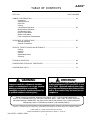
TABLE OF CONTENTS
SECTION
PAGE NUMBER
OWNER'S INFORMATION …………………………………………………………………………… 04
Unpacking
Setting the Unit
Electrical
Cooling
Low Ambient Operation ………………………………………………………………………… 05
Multiple Unit Operation
Condensate Piping
Electric Heat Option
Blower Information
Filter Installation / Replacement
SEQUENCE OF OPERATIONS ……………………………………………………………………… 06
Normal Operation
General Information
SERVICE, INSPECTIONS & MAINTENANCE ……………………………………………………
Cooling
Heating
Service
Replacement Parts
Cleaning
07
TROUBLE SHOOTING ………………………………………………………………………………… 08
COMPRESSOR CHECKOUT PROCEDURE ………………………………………………………
09
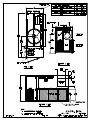
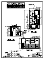
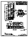
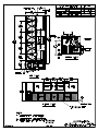
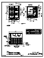
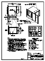
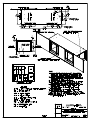
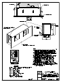
DIMENSIONAL DATA …………………………………………………………………………………
11
! IMPORTANT
▲
! WARNING
▲
The Clean Air Act of 1990 bans the intentional
venting of refrigerant (CFC's and HCFC's) as of
July 1, 1992. Approved methods of recovery,
recycling or reclaiming must be followed. Fines
and/or incarceration may be levied for noncompliance.
Improper installation, adjustment, alteration,
service or maintenance can cause property
damage, personal injury or loss of life.
Installation and service must be performed by
a qualified installer or service agency.
Owner should pay particular attention to the words: NOTE, CAUTION AND WARNING.
NOTES are intended to clarify or make the installation easier. CAUTIONS are given to prevent
equipment damage. WARNINGS are given to alert owner that personal injury and/or equipment
damage may result if installation procedure is not handled properly.
It is the intent of AAON, Inc. to provide accurate and current specification information. However, in the interest of product improvement,
AAON, Inc. reserves the right to change pricing, specifications and/or design of it's products without notice, obligation or liablity.
© 2000 AAON, Inc., all rights reserved throughout the world.
AAON & AAONAIRE are registered trademarks of AAON, Inc., Tulsa, OK.
HA USERS • P92200 • 2000
3
OWNER'S INFORMATION
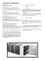
The HA Series units are designed for fast, easy installation as a self-contained cooling unit for outdoor installation only.
COOLING SECTION • DIRECT EXPANSION (DX)
All direct expansion refrigeration systems are factory
assembled, charged with refrigerant, tested and operated. On 13 - 25 ton units the refrigerant system includes
dual circuit evaporator and condenser coils providing
two stages of cooling. On 30 - 40 ton units the refrigeration system includes a four circuit evaporator coil and
two dual circuited condensor coils providing two or four
stages (optional) of cooling. These systems are provided
with liquid line filter driers, expansion valves and fully
hermetic compressors. Compressors are equipped with a
positive pressure forced lubrication system and crankcase heater. The air cooled condenser coil(s) is constructed of copper tubes with aluminum fins, the air is
pulled through with propeller fans. The evaporator coil
is draw through, made of copper tubes with aluminum
fins.
UNPACKING
When received, the unit should be inspected and
checked for damage that might have occurred in transit.
If damage is found, it should be noted on the carrier's
Freight Bill. A request for inspection by the carrier's
agent should be made in writing at once.
Before lifting the unit, be sure that all shipping material
has been removed from the unit.
Once shipping material has been removed, check inside
the unit control compartment for the field installed "PTrap" condensate connector. Also check the inlet air
opening for the filter rails and filters that are shipped
loose with the unit for field installation.
NOTE: Crankcase Heater Operation
Some units are equipped with a compressor crackcase
heater, which should be energized at least 24 hours prior
to setting the thermostat for cooling operation.
SETTING THE UNIT
If cable or chains are used to hoist the unit, care should
be taken to prevent damage to the cabinet.
Secure hooks and cables at all lifting points / lugs
provided on the unit. Hoist the unit to a point directly
above the pad, and lower unit into place. Make sure unit
is properly seated on the pad.
Never cut off the main power supply to the unit, except
for complete shutdown. When power is cut off from the
unit, any compressors using crankcase heaters cannot
prevent refrigerant migration. This means the compressor will cool down, and liquid refrigerant will accumulate in the compressor. Since the compressor is designed
to pump refrigerant gas, damage may occur when power
is restored.
If power must be cut off for more than an hour, turn the
thermostat system switch to "OFF", and leave it off until
the main power switch has been turned on again for at
least twenty four hours for units with compressor crankcase heaters. This will give the crankcase heater time to
clear any liquid accumulation out of the compressor
before it is required to run.
Always control the system from the thermostat, or control panel, never at the main power supply (except for
emergency or for complete shutdown of the system).
ELECTRICAL
A complete set of unit specific wiring diagrams in both
ladder and point-to-point form are provided with the
unit.
Check the unit data plate to make sure it agrees with the
power supply. The power and control wiring may be
brought to the unit through a hole in the side of the unit.
Protect the branch circuit in accordance with code requirements and connect power to the unit according to
the wiring diagram provided with the unit. If the control
wires are to run inside the same conduit, use 600 volt
wire or as required by applicable code. The unit must be
electrically grounded in accordance with the National
Electric Code.
Power wiring is to the unit terminal block or compressor
contactor. All wiring beyond this point is done by the
manufacturer.
After connecting the control wiring to the unit, power
may now be applied to the unit. Be sure that the
evaporator blower and condenser fan(s) rotate in the
proper direction (this applies only to units having three
phase blower motor).
!
▲
The refrigeration section of these appliances has been
found acceptable with applicable provisions of "ANSI /
UL 1995" and current "C.S.A. Standard C22.2" by E.T.L.
! CAUTION
▲
WARNING
On three phase units the rototation must be
checked on ALL MOTORS AND COMPRESSORS.
SCROLL COMPRESSORS ARE DIRECTIONAL.
Electric shock hazard. Can cause injury or death.
Before attempting to perform any service or
maintenance, turn the electrical power to unit to
OFF at disconnect switch(es). Unit may have
multiple power supplies.
Failure to observe the following instructions will
result in premature failure of your system, and
possible voiding of the warranty.
Rotation must be checked on start-up by a
qualified service technician using
suction and discharge gauges.
Scroll compressors will FAIL if run in the wrong
direction. Blower and condenser rotation
should be checked and only be altered if
necessary at the power connection.
4
OWNER'S INFORMATION
During the cooling season, if the air flow is reduced due
to dirty air filters or any other reason, the cooling coils
will get too cold and will cause excessive liquid to return
to the compressor. As the liquid concentration builds up,
oil is washed out of the compressor, leaving it starved for
lubrication.
ELECTRIC HEATING (Optional)
The electric heat is available as an option.
Heating is accomplished by passing electrical current
through a specified amount of resistance heaters which
will produce the required heat. The indoor blower motor
will energize at the same time as the heaters.
When heat is called for, the cooling section in inoperable
except for the indoor blower motor.
THE COMPRESSOR LIFE WILL BE SERIOUSLY
SHORTENED BY THIS REDUCED LUBRICATION,
AND THE PUMPING OF EXCESSIVE AMOUNTS OF
LIQUID OIL AND REFRIGERANT.
The system is designed to heat or cool a given amount of
air each minute it operates. If this amount of air is
greatly reduced (approximately 1/3 during the heating
season), the heater coil will overheat, and may cut the
heater off entirely by action of the safety high temperature limit device.
CAUTION:
While the following incorrect operations
may not cause damage to the system, they will impair the
performance, and may cause the built-in safety devices
to cut the system off completely.
1.
2.
BLOWER INFORMATION
LOW AMBIENT OPERATION
The cooling section of a direct expansion (DX)
unit will not operate properly when the outdoor
temperature is below 55° degrees. Outside air
intake options are recommended if operation
below 55° degrees is expected.
DUE TO JOB SPECIFICATION REVISIONS, IT MAY
BE NECESSARY TO ADJUST OR CHANGE THE
SHEAVE OR PULLEY TO OBTAIN THE DESIRED
AIRFLOW AT THE TIME OF INSTALLATION.
START-UP TECHNICIAN MUST CHECK BLOWER
MOTOR AMPERAGE TO ENSURE THAT THE AMPERAGE LISTED ON THE MOTOR NAMEPLATE IS
NOT EXCEEDED.
MULTIPLE UNIT OPERATION
When several units are used in conditioning the
space, and part or all of them are combination
heating-cooling units, all systems thermostat
switches must be set at either heating or cooling
(or set at "off"). Do not leave part of the systems
switched to the opposite mode. All cooling only
units should be switched to "off" at the thermostat during the heating season.
Clean blower wheels are necessary to reduce electrical
use, maintain capacity and reduce stress on the unit.
FILTER INSTALLATION / REPLACEMENT
Filter rails and filters are shipped inside the unit for
field installation. Install filter rails and slide filters
into place before operation of the unit.
To replace filters, slide each filter out of filter rack and
inspect. Replace old filters with the size indicated on
each filter. Be sure arrow points towards the blower.
CONDENSATE PIPING
The unit requires a drain trap to be connected to the
drain pan at the unit. If codes require a condensate drain
line, the line should be the same pipe size as the drain
nipple and should pitch downward toward drain.
The condensate drain pipe ("P" trap) is factory supplied
and is shipped loose in the control access compartment
for field installation. An air break should be used with
long runs of condensate lines.
Drain pans in any air conditioning equipment, even
when they have a built-in slope to the drain, will have
moisture present and will require periodic cleaning to
prevent any build up of algae of bacteria.
Cleaning of the drain pans will also prevent any
possible plugging of the drain lines and an overflow of the pan itself. All cleaning of the drain pans
and inside of the equipment should be done by
qualified personnel.
Filters should be checked every 30 days and replaced
or cleaned as necessary.
Do not permit the unit to be operated unless filters are
in place. Operation of the unit without filters will
result in a clogged evaporator coil.
IT IS IMPORTANT TO KEEP COILS,
BLOWER AND FILTERS CLEAN !
▲!
CAUTION
Before leaving installation, a complete
operating cycle should be observed
to verify that all components
are functioning properly.
5
SEQUENCE OF OPERATIONS
NORMAL OPERATION
I.
GENERAL INFORMATION
COOLING
Set the thermostat system switch to "COOL".
Set the thermostat fan switch to "AUTO" or "ON".
Set the thermostat temperature at the desired point.
A.
COOLING
1.
Packaged Units
When the thermostat calls for cooling from the space, 'Y1'
makes 'R' to 'CC1' through the LPS (low pressure switch),
HPS (high pressure switch) and optional GOT (guarantee off timer).
On larger units 'CC3' is also made. If additional cooling
is required 'CC2' and 'CC4' are made through their
respective pressure switches and timers.
HEATING
Set the thermostat system switch to "HEAT".
Set the thermostat fan switch to "AUTO" or "ON".
Set the thermostat temperature at the desired point.
AIR CIRCULATION
Set the thermostat system switch to "OFF".
Set the thermostat fan switch to "ON".
Do not change temperature setting.
With these settings, the air circulating blower will run
continuously but the air will not be heated or cooled.
B.
HEATING (Optional)
1.
Electric
When the thermostat calls for heat 'W1' makes 'R' to the
heat relay. All N.O. contacts close, and all N.C. contacts
open. The heat relay makes 'R' to the first stage of
electric heat.
SYSTEM OFF
Set the thermostat system switch to "OFF".
Set the thermostat fan switch to "AUTO".
Do not change temperature setting.
With these settings, the system is shut down, with the
exception of the control system power (24 volts), and the
crankcase heater of the compressor (about 60 watts).
On a fault condition the main limit located in the supply
air or the auxiliary limit located in the supply air fan
housing will remove power from all contactors.
If additional heating is required a second set of elements
can be turned on by 'W2'.
DO NOT TURN OFF THE MAIN POWER SWITCH.
NIGHT AND VACANT WEEKEND OPERATION
If it is desired to reduce the operating time during the
night, and during periods when the space is unused,
it is recommended that the temperature setting be
raised about five degrees during these periods of the
cooling season, and lowered about ten degrees during
the heating season.
6
SERVICING, TROUBLE SHOOTING, INSPECTIONS & MAINTENANCE
!
▲
SERVICE
In the event the unit is not functioning correctly and a
service company is required, a company with service
technicians qualified and experienced in electric heating and air conditioning be permitted to service the
systems in order to keep warranties in effect. The
service tech may call the factory if assistance is required.
WARNING
Electric shock hazard. Can cause injury or death.
Before attempting to perform any service or
maintenance, turn the electrical power to unit to
OFF at disconnect switch(es). Unit may have
multiple power supplies.
BEFORE CALLING, HE SHOULD HAVE THE MODEL
AND SERIAL NUMBER OF THE UNIT AVAILABLE
FOR THE CUSTOMER SERVICE DEPARTMENT TO
HELP ANSWER QUESTIONS REGARDING THE
UNIT.
COOLING
1.
Main Power Switches are on and power is to the unit.
AAON, Inc.
2.
Set thermostat in cooling mode and place the
"fan" switch to on. Check blower for correct operating
direction, amperage and voltage.
Check compressor(s) operation. Check the amperage
and compare to the nameplate data (check amperage
load side of the compressor contactor).
Phone: 918-583-2266
Fax:
918-382-6364
Customer Service Department
UNIT REPLACEMENT PARTS
Replacement parts for AAON equipment may be obtained from AAON. When ordering parts, always reference the unit model number, serial number and part
number.
ALWAYS USE AAON SPECIFIED PARTS
BLOWER
Inspect blower and blower section to keep free of dust or
debris. To clean the blower, turn the thermostat and the
power to the "OFF" position. Clean the assembly, check
the bearings for looseness, inspect the belt condition and
tightness, check screws for tightness, rotate blower
wheel and inspect for noise or roughness in the bearings.
COMMON CAUSES OF REDUCED AIR FLOW
A.
DIRTY FILTERS - Filters must be inspected and
replaced on a regular basis. It is strongly recommended
that the media be replaced monthly. Clean filters are
your best insurance against premature system breakdown. Do not permit the unit to be operated unless the
filters are in place. Operation of the unit without filters
will result in a clogged evaporator coil - a very expensive
service job to correct.
HEATING • ELECTRIC (IF APPLICABLE)
1.
Set thermostat in the heat mode.
2.
Set thermostat to call for heat to engage all
electric heat strips. Check blower for proper rotation
and voltage.
3.
Measure the amperage and voltage. Compare
them to the nameplate data.
B.
OBSTRUCTION TO AIR FLOW - Supply and
return air grilles must be kept clear so air can be freely
discharged and drawn from the system.
LUBRICATION
All original blower motors and bearings are furnished
with an orginal factory charge of lubrication. Some
applications will require that bearings be re-lubricated
periodically. The schedule will depend on the operating
duty, temperature variations or other severe atmospheric
conditions.
CLEANING
Inspect unit interior at the beginning of each heating
and cooling season and as operating conditions require.
COILS
Evaporator coil(s) should be inspected and cleaned annually to ensure there is no obstruction to air flow.
Condenser coil(s) should be inspected monthly. Clean
condenser coils annually and as required by location or
outdoor air conditions.
Bearings should be re-lubricated when at normal operating temperatures, but not running. Rotate the fan
shaft by hand and add only enough grease to purge the
seals. DO NOT OVERLUBRICATE.
Recommended greases are:
SHELL OIL - DOLIUM R
CHEVRON OIL - SRI No. 2
TEXACO INC. - PREMIUM RB
!
▲
WARNING
All of the items listed under the service, trouble
shooting, inspections and maintenance section of
this manual should be performed once a year.
7
SERVICING, TROUBLE SHOOTING, INSPECTIONS & MAINTENANCE
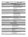
POSSIBLE CAUSE
TROUBLE
COOLING PACKAGE
SYSTEM OFF
1. Check power at lineside of contactor(s).
2. Thermostat not set for cooling.
3. High pressure control tripped.
4. Low pressure switch open (loss of charge).
CONDENSER FAN WILL NOT RUN
1. Overload thermal protector open in motor.
2. Motor run capacitor open or shorted.
3. Motor failed.
4. Fan or shaft stuck.
EVAPORATOR BLOWER WILL NOT RUN
1. Overload thermal protector open in motor.
2. Relay not closing.
3. Motor failed.
4. Capacitor shorted or open (PSC motors only).
5. Stuck shaft or blower wheel.
COMPRESSOR SHORT CYCLES
1. Check for low refrigeration charge.
2. Compressor overload setting.
3. Ambient temperature too low.
4. Filters dirty or air flow restricted.
5. Evaporator blower not running.
FAN MOTOR RUNS HOT AND CUTS OUT
1. Line voltage too high.
COMPRESSOR WILL NOT START
1. Line voltage too low.
2. Limit switches are open.
3. Overload or pressure control tripped.
BLOWER DOES NOT DELIVER AIR
1. Blower running backwards.
2. Dirty filters.
3. Duct obstruction.
4. Belts loose.
ELECTRIC HEATING
SYSTEM OFF
1. Check power at line side of contactor(s).
2. Thermostat not set for heating.
EVAPORATOR MOTOR WILL NOT RUN
1. Overload relay tripped.
2. Heater Relay not energized.
3. Blower Contactor not energized.
4. Capacitor shorted or open (PSC motors only).
BLOWER DOESN'T DELIVER AIR
1. Blower running backwards.
2. Dirty air filters.
3. Dirty coils.
4. Duct obstruction.
5. Belts loose.
BLOWER COMES ON, BUT LITTLE OR NO
HEAT
1. One or more heater contactors are open.
2. Limit switches are open.
3. Heater relay open.
4. Heat strips burned out.
8
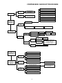
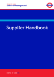
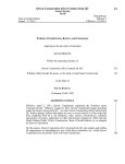
COMPRESSOR CHECKOUT PROCEDURE
CONTROL PANEL NOT SET FOR COOLING
THERMOSTAT NOT CALLING FOR COOLING
POWER TO
UNIT
CHECK UNIT FUSES
AND WINDING
LO PRESSURE SWITCH OPEN
NO POWER TO
CONTACTOR
HI PRESSURE SWITCH OPEN
NO POWER TO
UNIT
CHECK CIRCUIT BREAKER AT
POWER DISTRIBUTION PANEL
COMPRESSOR LOW AMBIENT LOCKOUT OPEN
(TEMPERATURE OUTSIDE BELOW 55 DEG.)
TRANSFORMER OPEN
BROKEN OR LOOSE CONTROL
NO 24 VOLT POWER
TO HOLDING COIL
COMPRESSOR
WON'T RUN
CONTACTOR
OPEN
POWER TO HOLDING COIL
POWER TO CONTACTOR
ALL 3 LEGS
HOLDING COIL BURNED OUT
REPLACE CONTACTOR
COMPRESSOR RUNS
COMPRESSOR
HUMS
STUCK COMPRESSOR
REVERSE LEADS
GROUNDED WINDING
REPLACE
COMPRESSOR
MOTOR WINDING OPEN
CONTACTOR
CLOSED
MOTOR
WINDING OPEN
POWER TO
COMPRESSOR
ALL 3 LEGS
INTERNAL
OVERLOAD OPEN
COMPRESSOR
DOESN'T HUM
NO POWER TO
COMPRESSOR
COMPRESSOR RUNS
OR
COMPRESSOR CYCLES
(Poor Cooling)
BROKEN LEADS
COMPRESSOR
DOESN'T RUN
REPLACE
COMPRESSOR
REPLACE
COMPRESSOR
IF COMPRESSOR DOME IS HOT,
IT MAY BE LOCKED OUT ON
INTERNAL OVERLOAD.
WAIT FOR RESET, IT COULD TAKE
AS LONG AS 2 HOURS.
REPLACE LEADS
LOW AIR (CONDENSER)
OVERCHARGE OF REFRIGERANT
HIGH HEAD
PRESSURE
AIR IN SYSTEM
DIRTY CONDENSER COIL
CHECK COMPRESSOR
ROTATIONAL
DIRECTION
LOW HEAD
HIGH SUCTION
PRESSURE
LOW
SUCTION
PRESSURE
DEFECTIVE COMPRESSOR VALVES
REPLACE COMPRESSOR
LOW AIR (EVAPORATOR)
CHECK FILTERS,
OR DIRTY EVAPORATOR COIL
OR LOOSE BELT
LOW REFRIGERANT CHARGE
RESTRICTED FEEDER TUBE
BAD EXPANSION VALVE POWER ELEMENT
9
NOTES:
10
AAON
®
HA COOLING UNITS
•
USERS
INFORMATION
MANUAL
AAON, Inc.
2425 South Yukon
Tulsa, Oklahoma U.S.A. 74107
ph: (918) 583-2266 • fax: (918) 583-6094
P92200 • HA Users • 2000
12