1
Session 12c6
Driver) or a part of controller (Component Driver). In this
application the use of instrument control tools is oriented to
teaching, and handling control panels is very important
given that students learn to operate the whole choices of
each instrument easily. When there is no enough knowledge
about SICL´s instructions or choices of an instrument, the
Component Driver is the best solution because it provides
higher speed and only sends and receives the needed data for
implementing a particular task. Also this object has a list of
instructions and information for supporting the learning
about choices of each instrument.
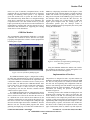
GPIB bus, or displaying stored data in a file (Figure 3). This
program loads in the computer memory an interrupt control
routine and associates it to parallel port (IRQ7). The line
SRQ (Service Request) from GPIB bus [5][8] is used to fire
the interrupt routine and read the data from bus. For
avoiding the possible loss of data because of GPIB bus
higher speed compared with the reading speed of a
conventional parallel port, the interrupt routine of
WATCH_GPIB program stops temporarily bus activity until
reading the suitable data.
GPIB Bus Monitor.
The programmable instrumentation GPIB bus is a parallel
connection bus in which all devices share the line signals
[3][5][29], and requires the existence of some equipment for
mastering those signals.
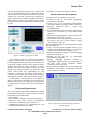
Figure 4. Flowcharts for implementing and designing
laboratory practices.
Using the GPIB Bus Monitor the students can visualize
the commands and data that is sending through the bus a
particular instrument from SIP (Figure 1).
Figure 3. Screen of WATCH_GPIB program.
Implementation of Practices.
The GPIB Bus Monitor (Figure 1) designed for teaching
the IEEE 488 instrumentation bus, allows to display in real
time, and without lost of information the signal lines that
conform the GPIB bus. Given that a device can only access
the bus when it is addressed, the GPIB Bus Monitor must
not be a bus device since it must read the state continuously,
and for this reason it must not have any address,
consequently it does not exist from the controller and the
whole bus devices point of view.
The GPIB Bus Monitor has been implemented by means
of a PC under MS-DOS (Table 1). The GPIB interface cards
able to connect a PC to the bus do not allow the access to it
in a different time to the card has been addressed by the
controller, and therefore are not useful for this purpose. For
this reason is used an I/O Card adapted for reading the eight
data lines and the eight control lines of GPIB bus. The Bus
Monitor runs the WATCH_GPIB program that allows
gathering and displaying in real-time the available data on
The practices are designed in such a way that students can
handle the development environment and visualize the GPIB
bus. The two first practices are oriented to introduce them
the VEE tool and explaining SIP configuration. Both are
shown in auto-learning form and introduce step-by-step the
method of using the VEE environment, and the control of
instruments for making the practices, according the
flowchart of figure 4a.
Following practices allow students developing their own
programs using existing tools, and at any time they can
access directly to the SIP for connecting their electronic
circuits under test. For example, the practice three is oriented
to design a VEE program using the needed instruments for
implementing Bode´s diagrams (module and phase) of a RC
circuit frequency response. Also shown to the students are
the choices used to identify and compare the three control
types of instruments (Table 2), and the way VEE objects are
0-7803-5643-8/99/$10.00 © 1999 IEEE
November 10 - 13, 1999 San Juan, Puerto Rico
29th ASEE/IEEE Frontiers in Education Conference
12c6-8