1
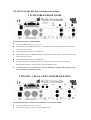
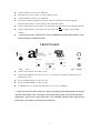
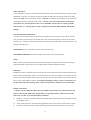
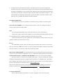
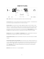
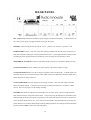
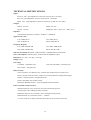
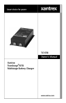
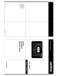
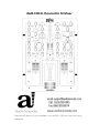
AEM-100i 2-Channel Pro DJ Mixer
Please kindly read this manual before using the AEM-100i and save it for future
reference.
TABLE OF CONTENTS
Warranty Information
Getting started
Turntables rear panel
CDs rear panel
Front panel
Before powering up the unit
After powering up the unit
Faceplate details
MICs, Inputs, Master, headphones
Effects
Channel LED meters
Line Faders, Crossfader
Front panel details
Rear panel details
Block Diagram
Specifications
p. 3
p. 4-7
p. 4
p. 4-5
p. 5
p. 6
p. 7
p. 8-12
p. 9
p. 9-11
p. 11
p. 11-12
p. 13
p. 14
p. 15
back cover
Thank you for purchasing the AEM-100i featuring:
Unique knob controlled dual effect section with individually
controllable filters and sound generators
Line faders with full curve control and reverse.
Extremely durable Pro X Fade crossfader
Up to 8 line level inputs, 2 turntable inputs, and 2 microphone inputs
Balanced Master XLR Outputs
We hope you enjoy our mixer as much as we enjoyed making it!
2
AEM-100i Audio Innovate Warranty and Servicing Policy
Audio Innovate provides a warranty against manufacturing defects for either 1 year after the date of
purchase or 90 days after warranty repair is made, whichever is later. This warranty does not cover
minor visual defects such as scratches and paint wear or defects caused by uses other than the intended
use. In addition, the warranty does not cover damage to the unit due to mishandling by the user or
technicians not specifically authorized by Audio Innovate.
Please go to the website www.audioinnovate.com to register the purchase of your product. Please
save your receipt as a record of your purchase. We also recommend that you save the original packaging
in the event that the product needs to be returned under warranty. You can also order original packaging
through the www.audioinnovate.com website in the event you need it for returning or shipping the
product.
For repairs made under warranty, Audio Innovate will reimburse the cost of standard nonexpedited shipping from the customer and will cover return shipping and repair costs. If the customer
requires faster shipping, Audio Innovate will only bill the difference between the cost of the faster
shipping and regular shipping. For all other repairs, the customer must pay for all shipping and repair
costs.
Customers shall contact Audio Innovate directly prior to sending product back for service. If Audio
Innovate determines that the product requires repair, Audio Innovate will issue an RMA number for the
product and the customer shall indicate the RMA number on the mailing label. Prior to issuing an RMA
number, Audio Innovate will clarify what repairs will be done and what will be covered under warranty.
If during the repair Audio Innovate finds additional issues with the product, Audio Innovate will contact
the customer and confirm repairs required and costs prior to proceeding.
All product returned shall be shipped in the original packaging. In the event that the product is
damaged during shipping due to improper packaging, Audio Innovate may require the customer to pay
for repairing such damage.
Audio Innovate may request a copy of your receipt as proof that the product is covered under
warranty.
Please staple your receipt here and save for future reference.
3
GETTING STARTED: Basic hookups and settings
2 TURNTABLES REAR PANEL
REAR PANEL USING 2 TURNTABLES:
AC power adapter connects to “20V~1A”
Left turntable goes to “PHONO1/LINE1” using dual RCA cords, and the ground wire goes to the
GND screw above AUX2
“LINE1/PHONO1” switch set to “PHONO1”
Right turntable goes to “PHONO2/LINE3” using dual RCA cords, and the ground wire goes to the
GND screw above AUX1
“LINE3/PHONO2” switch set to “PHONO2”
For powered speaker or amplifier connection, either use XLR cables on the “MASTER
BALANCED OUTPUT” or RCA cables on the “MASTER” output.
***Only turn the power switch on once you have finished the hookup, understand the setup,
and set all faders to minimum volume.
2 SINGLE / 1 DUAL CD PLAYER REAR PANEL
REAR PANEL USING 2 SINGLE CD PLAYERS / 1 DUAL CD PLAYER:
AC power adapter connects to “20V~1A”
Left CD source goes to “LINE 2” using a dual RCA cord.
4
“LINE1/PHONO1” switch set to “PHONO1”
Right CD source goes to “LINE 2” using a dual RCA cord.
“LINE3/PHONO2” switch set to “PHONO2”
For powered speaker or amplifier connection, either use XLR cables on the “MASTER
BALANCED OUTPUT” or RCA cables on the “MASTER” output.
Connect “Fader Start A” using a mono 1/8” jack cable to the left CD player input marked “Remote”.
Connect “Fader Start B” using a mono 1/8” jack cable to the right CD player input marked
“Remote”.
***Only turn the power switch on once you have finished the hookup, understand the setup,
and set all faders to minimum volume.
FRONT PANEL
Connect a microphone to the “MIC1” input
Connect the headphones either to the 1/8” or 1/4” socket above “PHONES” depending on the
headphone jack size.
Set the “FADER START” to “OFF” for now.
Set the “CROSSFADER” to “OFF” for now.
“FADER CUTS” isn’t used on the AEM-100i; you can set to “NORMAL”.
***Please note that all of these settings are simply for getting up and running quickly for the first
time with a basic audio setup. Most likely you purchased this product for its advanced features
and hookups. Please only use these options once you are familiar with the product and practice at
home before you attempt to use them in a live situation.
5
Before powering up the unit:
1) Make sure the PHONO / LINE switches at the top are set to match the hookups in the back.
2) Set all EQ faders to the middlePlace both WET/DRY faders in the DRY position.
3) In the MAIN section, set the MASTER to MIN and the BALANCE in the middle.
4) Set both CH1 and CH2 faders to minimum, Reverse = OFF, and Slope in the middle.
5) Make sure the Amplifier or powered speaker is set to MIN volume or off.
6) Make sure the MIC1, MIC2, and PHONES GAIN are all set to – or MIN.
6
After powering up the unit:
Do the following in order while music is playing for both CH1 and CH2
1) Adjust the GAIN knobs until the CH1 and CH2 meters peak at about 0dB
2) Move the CH1 slider about 2/3 of the way up.
3) Adjust the MASTER volume until the LEFT and RIGHT led meters peak at about 0dB.
4) Adjust the amplifier / powered speaker volume until the sound is at a comfortable mixing
level.
Following these steps will maximize the audio fidelity of the AEM-100i mixer. Please note if
your amplifier or powered speaker does not have a volume adjustment, please do not do steps 2-4
and instead, adjust the master knob to obtain a comfortable mixing level. Also once you are done
adjusting, you should leave the MASTER volume or amplifier / powered speaker volume settings
alone to prevent distortion and speaker damage.
At this point, move the CH1 fader to the bottom and you’re ready to start mixing!
7
The above is just a “quick start” guide for getting the mixer up and
running for the first time, especially in an emergency. Please read
through the remainder of the manual and especially pay close attention
to functions that you haven’t used before in other mixers.
AEM-100i FACEPLATE
8
MIC1 and MIC2:
The microphones connect via the front panel on the left side. Each microphone has bass, treble, and gain
adjustments. The turn-on switch has 3 positions; ON is for adding the microphone output to the main
PFL output, OFF is for no microphone output, and TALK is for adding the microphone to the output and
reducing the main PFL output by about 17dB. ***Before you set the switch ON for the first time,
please make sure the microphone GAIN is set to minimum, and increase the volume gradually
with extreme care. Turning up the GAIN too quickly can result in audio feedback and speaker
damage.
CH1 and CH2 INPUT SECTION:
A selector switch chooses between a Phono/line switchable input, line input, and Aux input. Note the
Aux input has a jack in the front and another in the back, which add together so the DJ can use either
input or both. ***Both AUX front and back inputs can be used only if the audio on both sources won’t be
playing at the same time.
POWER LED turns on when there is power coming into the unit.
MASTER LED METERS indicate the output on the master left and right speakers.
MAIN
Balance L/R allows panning between the left and right outputs. Booth controls the level of the booth
output and Master controls the level of the Master RCA and Master Balanced Output.
PHONES:
Headphone output. Cue/Master knob controls the ratio of sound from the sources selected with the CUE
buttons and the master output. Split Cue controls how the sound is heard; if Split Cue is pressed, the Cue
sound is in the left ear and the Master sound is in the right; otherwise, both sounds are mixed for both ears.
Gain controls the headphone volume. To avoid hearing damage, before you press CUE buttons for
the first time with music playing, set the volume low and increase until the level is comfortable.
EFFECT SECTION:
***Before you start using the effects, first turn all effect knobs all the way counterclockwise, the
Phaser is deactivated (LED is off), and the filter is in the OFF position. This way you can add
effects one at a time as you become familiar with them.
1)
Wet/Dry: Use this to crossfade between the original audio sound (dry) and the sound effect created
by the effect knobs.
2)
Noise: Adds white noise to both left and right of the input source material, Gain controls volume.
3)
Oscillator: Adds square wave to both left and right of the input source material. Gain controls
9
volume, and Hz controls frequency.
4)
Stutter: Cuts the source material in and out. The leftmost position is off. When turning the knob
clockwise, the stutter starts at a low speed and increases. As the knob is rotated, the cutting of the
material starts to produce an audible tone, which increases in frequency.
5)
Digitize: Samples and holds the source material. The leftmost position is off. As the knob is
rotated clockwise, the music sounds like the sampling rate and bit depth of the material is being
reduced to give you a grainy digital effect.
6)
Phaser: Creates a heavy chorusing and filtered effect known as Phasing. As the knob is rotated
clockwise, the Phasing sound increases in pitch and in intensity. ***Use the engage button to
activate this function.
7)
Band Pass: Uses both the high pass and the low pass filter to select a frequency range for the output.
You can start out with the High Pass filter in the leftmost position and the Low Pass filter in the
rightmost position. The music starts out normally and as the high pass knob is turned clockwise and
the low pass knob is turned counterclockwise, the low end (bass drum) and high end (hi hat) will
disappear. Both knobs can be moved in the same direction to select a specific frequency range.
***Note the band pass filter function is different from EQ’s. The EQ’s will only boost or cut three
specific frequency ranges, low end, midrange, and high end.
8)
Band Cut: Uses both the high pass and the low pass filter to select a frequency range for cutting
from the output. You can start out with the High Pass filter in the rightmost position and the Low
Pass filter in the leftmost position. The music starts out off. As the high pass knob is turned
counterclockwise the high end will come in (high hats). As the low pass knob is turned clockwise,
the low end (bass drum) will come in. Both knobs can be moved in the same direction to cut the low,
mid, or high range output. ***Note the band cut filter function is different from EQ’s. The EQ’s
will only boost or cut three specific frequency ranges, low end, midrange, and high end.
9)
Cue: Use for cueing the fully wet effect sound through the headphones. You can test the effect
sound by doing this with the Wet/Dry slider in the dry position and then moving it to the Wet
position when the correct effect sound is achieved.
Some effect suggestions:
1) The signal flow of the effects section is in order from left to right then top to bottom. This allows
effects to be combined in a logical way. For example, the noise may sound bland to you, so you can
digitize it and use a band pass filter for an interesting effect. If digitize sounds too harsh then you
can use a band pass filter and cut out the high end for another unique effect.
2) An important thing to keep in mind is to experiment and see how many new and innovative effects
you can create. Try using the oscillator as well as the noise generator to create analog synth type of
effects over music. Filter it using the other effects to create the sound you want. Take this sound and
then use the fader cuts buttons to cut the sound in and out. Modify the sound by turning the oscillator
knob or sweeping the filters at the same time you work with the fader cuts.
10
3) The effect section of the AEM-100i is like an instrument; the more you practice and push the
boundaries, the better you will become at using it. Don’t be afraid to really get into the effect section,
and master its capabilities. If you run music thru the effects as well as use the effects to add elements
to the music you will begin to understand what is possible with this tool and how to master it. Since
all of the effects are designed to work together, practice one effect at a time first and then overlay
them once you are familiar with what the individual effects do.
CH1/CH2 LED METERS:
These indicate the mono level of channel 1 and channel 2 PFL (pre fader level) audio signals.
CH1, CH2 LINE FADERS: Use to control the channel volume. There are 2 settings here that are
critical to proper operation of these faders:
Slope
For the standard smooth fader slope, set the slope knob to the center 12:00 position.
Turn the knob counter-clockwise for a sharper cut-in at the bottom and a more gradual slope at the
top. The leftmost position is good for transforming type effects with the fader
Turn the knob clockwise for a more gradual cut-in at the bottom and a sharp slope at the top. The
rightmost position is good for the Euro-scratch.
Reverse
For standard fader operation where the sound is off at the bottom and increases as you move the
fader up, set Reverse to OFF. If you’d like to reverse the operation of the fader so that the sound is off at
the top and comes in as you move the fader down, set Reverse to ON.
PRO X FADE CROSSFADER: The crossfader allows DJs to mix between the CH1 and CH2 sources.
The DJ can use the crossfader to output CH1, CH2, or a combination of both. Please see below for the
CROSSFADER SLOPE and NORMAL/OFF/REVERSE on how to set up and use the crossfader.
Using a crossfader is a skill that you can master with practice. The Pro X Fade has been specially
designed to withstand the most intense rugged use and is good for over 4,000,000 cycles. Beyond the
basic crossfader usage, there are plenty of online resources to get you started. You can start by going to
the Pro X Fade website for instructional videos at www.proxfade.co.uk .
There are also online forums where you can get more information about crossfaders and turntablist
products in general such as www.eclecticbreaks.proboards57.com/ and www.skratchlounge.com.
Crossfader Maintenance
Note the PRO X FADE has adjustable cut in points, adjustable tension, and can be easily
11
maintained and cleaned. It also already comes with the cut in points pre-adjusted for minimum dead
space. Please see www.proxfade.co.uk for more information on how to adjust and clean the crossfader.
Also check our website www.audioinnovate.com for information on accessories for cleaning and
adjusting the crossfader.
***VERY IMPORTANT: Because of the skill required to adjust and clean the crossfader, you shall
refer this operation to a qualified technician. The power cord must be unplugged before servicing or
damage to the unit may result. The faceplate and only the faceplate should be removed using a Phillips
screwdriver to access the crossfader. Knobs should all be removed by hand or very carefully lifted with
a screwdriver to avoid scratching and product damage. Please make sure that all parts are kept in a bin so
they are not misplaced prior to reassembly.
***SPECIAL NOTES FOR CLEANING THE CROSSFADER: In order to remove the crossfader
case for lubrication, you will first need to loosen the Phillips screw at the bottom of the crossfader.
Otherwise, you may damage the crossfader case when trying to remove it. In addition, please follow the
instructions for lubrication exactly or the fader will either be over-lubricated, causing fader noise, or
under-lubricated, causing the fader to wear more quickly.
12
FRONT PANEL
MIC1, MIC2 connect 1/4” stereo jack microphones to either or both of these inputs.
AUX1, AUX2 connect 1/8” stereo jack input sources such as IPods or computers. ***Note that the front
AUX1 and AUX2 inputs are added to the rear AUX1 and AUX2 inputs.
FADER START turns the fader start function ON or OFF. When ON, this causes the audio on either
channel to cue or pause when the crossfader volume is turned off and to play when the crossfader volume
is turned on. ***Note that the fader start function is also activated by the Fader Cuts buttons if using
these buttons turns the sound on and fully off. Also note that when the CROSSFADER switch is set to
the OFF position, the fader start function is controlled by the line faders instead of the crossfader.
FADER CUTS selects between NORMAL and REVERSE fader cuts. Note this feature is removed on
the AEM-100i so this selection will not have any effect on the mixer operation.
CROSSFADER SLOPE adjusts the rate at which the sound source cuts in and out when the crossfader
is moved.
CROSSFADER NORMAL/OFF/REVERSE selects the direction of the crossfader and whether or not
it is active. ON makes the crossfader work normally where the sound comes in when the fader is moved
toward the channel. OFF disables the crossfader operation so just the line faders control the output
sound. REVERSE makes the crossfader work backwards so the sound comes in when the fader is
moved away from the channel.
PHONES connects to either 1/8” or 1/4” jack headphones.
13
REAR PANEL
20V~1A AC IN input from the transformer power supply included with the mixer. ***Please make sure
the correct power supply is plugged in before turning on the power.
POWER Used for turning the unit on and off. The “1” position is on and the “0” position is off.
FADER START Connect a 1/8” mono jack cable (usually included with the CD player) from here to a
fader start compatible CD player to use the Fader Start function. ***Note that audio RCA cables provide
grounding for these signals and must be hooked up to the CD player for this function to work.
MASTER BALANCED OUT Used for high quality XLR connections to the master speakers or amp.
OUTPUT MASTER Used for standard 1/4” RCA outputs to the master speakers or amp.
OUTPUT BOOTH Standard 1/4” RCA outputs to speakers used in the DJ booth. ***Please make sure
that these outputs are not used for the main audio output because the LED meters show the output on the
master line and not on the booth line.
OUTPUT RECORD Line level output used for analog recording. This is the PFL input to both the
Master and Booth outputs. ***Please only use this for recording because there is no master volume
control. The level is properly set for analog recording.
CH1/CH2 Both inputs have Phono/Line switchable, Line, and Aux inputs. The Aux inputs from the
back combine with the Aux inputs from the front. ***If you are using the Phono/Line switchable inputs,
make sure that the Phono/Line switch is set properly or the sound will distort (Line input set to Phono) or
will be too quiet (Phono set to Line). Also, when you use turntables, if the turntables have ground screws,
please make sure to use RCA cables which include an added ground wire for hookup to both the turntable
grounds and the GND pins above the CH1/CH2 inputs.
14
BLOCK DIAGRAM:
15
TECHNICAL SPECIFICATIONS:
Inputs:
Line/Aux: 10kΩ input impedance, 5.6mV rms sensitivity for 1.0V output
Mic: 10kΩ input impedance, 1mV rms sensitivity for 1.0V output
Phono: 47kΩ input impedance, 0.9mV rms sensitivity @ 1kHz for 1.0V output
Outputs:
Master: 8.6V rms
Booth: 8.6V rms
Record: 1.0V rms
Headphone Amp: .5 watts / 47Ω, THD < 0.1%
Equalizer:
3-band Stereo Equalizer per channel, -30dB cut / +10dB boost
Signal to noise ratio
Line: 92dB (JIS-A)
Aux: 92dB (JIS-A)
Mic: 87dB (JIS-A)
Phono: 83dB (JIS-A)
Frequency Response
Line: 20Hz~20kHz 1dB
Aux: 20Hz~20kHz 1dB
Mic: 20Hz~15kHz 1dB
Phono: RIAA 0.5dB
Talkover attenuation: Maximum –19dB, minimum –16dB attenuation of main audio
Power consumption: 18 Watts typical, 22 Watts with full headphone output
Dimensions: 10” wide * 14” deep * 4.2” high
Weight: 6.0kg
Life rating:
Crossfader: >4,000,000 cycles
CH1, CH2 Line faders: >100,000 cycles
Misc. faders: >100,000 cycles
Effect circuitry:
Noise, Oscilattor: 0 to 3dB max level, oscillator has variable frequency square wave.
Stutter: variable on/off from a few 1/10ths of a second transforms to high pitched ringing.
Digitize: variable frequency sample/hold circuit.
Phaser: dual phaser with variable cutoff.
Band Pass, Band Reject filters: 4-pole sweepable butterworth filters.
Fader/Crossfader section circuitry:
Minimum slope has cut-in of 1mm or less at the lowest audio position.
Average slope uses 0.2dB typical fader resolution
Maximum slope has cut-in of 1mm or less at the highest audio position.
Maximum delay on VCA fader controls = 1.64msec.
***VCA circuit has no delay in the audio path, delay is for the audio control only.
16