1
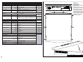
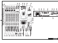
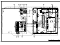
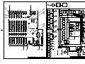
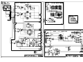
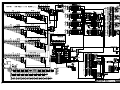
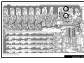
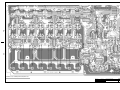
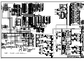
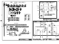
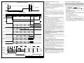
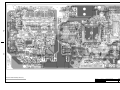
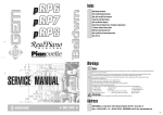
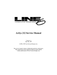
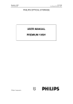
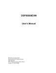
Index
2
3
4
5
6
7
8
9
10
11
12
13
14
15
16
Technical Specifications, Opening Instructions
Layout
Parts Assembly 1
Parts Assembly 2, Block Diagram
Power Supply, Virtual Strip, Logo Led and I/O & Phones Schematics
Power Supply, Virtual Strip, Logo Led and I/O & Phones Pcb Layouts
Controls & I/O Schematics (part 1 of 2)
Controls & I/O Schematics (part 2 of 2)
Controls & I/O Pcb Layout (part 1 of 2)
Controls & I/O Pcb Layout (part 2 of 2)
Cpu/Dsp & AD/DA Schematics (part 1 of 2)
Cpu/Dsp & AD/DA Schematics (part 2 of 2), Hybrid Mic/Line and Output Schematics
Timings, Update Procedure, Memory Reset Procedure, Potentiometers Calibration Procedure
Cpu/Dsp & AD/DA Pcb Layout
Spare Part List
Warnings
SERVICE MANUAL
Notice
Service must be carried out by qualified personnel only.Any tampering carried out by unqualified personnel during the guarantee period
will forfeit the right to guarantee.
For a correct operation of the instrument, after having switched off, be careful to wait at least 3 seconds before switching on again.
To improve the device's specifications, the schematic diagrams may be subject to change without prior notice.
All components marked by this symbol have special safety characteristics, when replacing any of these components use only
manufacturer's specified parts.
The (µ) micro symbol of capacitance value is substituted by U.
The (Ω) omega symbol of resistance value is substituted by E.
The electrolytic capacitors are 25Vdc rated voltage unless otherwise specified.
All resistors are 1/8Ω unless otherwise specified.
All switches shown in the "OFF" position. All DC voltages measured to ground with a voltmeter 20KOhm/V.
Soldering point.
Supply voltage.
Logic supply ground.
Male connector.
Test point.
Analog supply ground.
Female connector.
M/F faston connector.
Flag joined with one or more flags
Chassis ground.
with the same signal name inscribed.
Earth ground.
ATTENTION
Observe precautions when handling electrostatic sensitive devices.
Address
L CODE: 270191M
GENERALMUSIC S.p.A. Sales Division: 47842 S.Giovanni in Marignano (RN) ITALY - Via delle Rose, 12 - tel. 0541/959511 - fax 0541/957404
GENERALMUSIC on the NET: http://www.generalmusic.com
1J
FALCON • TECHNICAL SPECIFICATIONS
SECTION
MONO INPUT CHANNEL
MIC/LINE A input
LEVELS & DATA
sensitivity
PAD
impedance
LINE B input
sensitivity
impedance
A/D converter
EQ
HIGH
MID
LOW
STEREO INPUT CHANNEL
LINE input
sensitivity
impedance
A/D converter
EQ
HIGH
HI-MID
LO-MID
LOW
STEREO DIGITAL INPUT
Format
Level
MASTER SECTION
MIX 1 ouputs
D/A converter
impedance
D/A converter
output level
impedance
AUX 1&2 outputs
D/A converter
output level
impedance
DIGITAL output
format
output level
HEADPHONES output
from +4 to -10dB
10kOhms
18 bit linear, oversampling 64 times
±15dB, from 40Hz to 16kHz, from SHELVING to Q=10
±15dB, from 40Hz to 16kHz, from SHELVING to Q=10
±15dB, from 40Hz to 16kHz, from SHELVING to Q=10
±15dB, from 40Hz to 16kHz, from SHELVING to Q=10
IEC958 Professional (AES/EBU)
RS422
output level
MIX 2 ouputs
from -20 to -60dB
30dB
2kOhms / 10kOhms
from +10 to -30dB
10kOhms
20 bit linear, oversampling 64 times
±15dB, from 40Hz to 16kHz, from SHELVING to Q=10
±15dB, from 250Hz to 16kHz, from Q=0.7 to Q=10
±15dB, from 40Hz to 16kHz, from SHELVING to Q=10
minimum impedance
output level
20 bit linear
+4dB
600 Ohms
18 bit linear
+4dB
600 Ohms
20 bit linear
+4dB
600 Ohms
IEC958 Consumer (S/PDIF)
0.5Vpp/75Ohms
32 Ohms
2W
Opening
Instructions
CONNECTORS
Disconnect the instrument
from the mains.
Carefully turn the mixer over
and unscrew the screws
marked with the arrows.
Hold the top and bottom
chassis tightly and turn the
the mixer right way up, lift off
the top chassis as shown
below with care without
forcing the cables.
Balanced
XLR-F
Balanced
JACK
Balanced
JACK
XLR-F
Balanced
XLR-M
Impedance
Balanced
JACK
Impedance
Balanced
JACK
Phono RCA
Stereo
JACK
GENERAL SPECIFICATIONS
Sampling frequency
48kHz
Dynamic range
117dB
adiacent input CH -90dB @ 1kHz
Crosstalk
input to output -100dB @ 1kHz
PAN -85dB @ 1kHz
all faders closed -110dB
Noise
MIX fader nominal -105dB
MIX fader nominal + 1 CH -95dB
Total harmonic distorsion
<0.03%, 20Hz - 20kHz
(THD + Noise)
<0.02%, 20Hz - 20kHz
kg 5.7
Weight
mm (WxHxD) 440x110x500
Dimensions
J2
DRW G.Boccato
DWG# 550638
PCB#
GENERALMUSIC S.p.A. ITALY
CKD M.Mulazzani
DISK: 4 PRT: 1/1
Opening Instructions
APP. F.Gazzilli
REV: 05/05/99
ALL RIGHTS ARE RESERVED, NO COPIES
OR REPRODUCE THIS DOCUMENT WITHOUT
WRITTEN CONSENT BY GENERALMUSIC.
3
3
23
3
22
21
2
1
3
24
4
25
26
27
26
28
29
30
31
5
6
7
10
8
11
7
10
7
20
10
33
32
19
8
11
18
8
11
17
7
12
9
13
13
13
13
13
13
14
14
8 11
8 11
15
8 10
8 11
16
3J
25
33
34
35
24
36
43
44
CN31
CN7
37
CN3
CN2
CN4
21
CN1
CN5
CN1
CN2
CN1
CN2
CN4
CN3
39
CN5
CN1
CN3
45
CN9
CN8
CN1
CN14
CN7
CN2
CN7
CN13
CN6
CN6
CN10
CN12
CN5
CN26
CN11
CN5
CN1
CN4
CN4
CN9
CN3
46
CN2
CN1
CN6
CN28
CN3
41
J4
38
40
CN29
CN30
49
DRW G.Boccato
DWG# 550636
PCB#
GENERALMUSIC S.p.A. ITALY
CKD M.Mulazzani
DISK: 4 PRT: 1/1
APP. F.Gazzilli
REV: 05/05/99
Parts Assembly 1
(for descriptions see REF column on Spare
Part List further on this manual.)
ALL RIGHTS ARE RESERVED, NO COPIES
OR REPRODUCE THIS DOCUMENT WITHOUT
WRITTEN CONSENT BY GENERALMUSIC.
POWER
SWITCH
2
238086
TRANSFORMER
60W 230Vac (EU)
230087
TRANSFORMER
60W 115Vac (US)
CN2
CN1
768197 - MAINS
FILTER BOARD
23
3
+48V
50
CH1
IN A
MIC-XLR
BALANCED
PAD
-30dB
768190 - POWER SUPPLY BOARD
CN11,12,13,14
GAIN
A/B
+
-
22
+48V
PHANTOM
SUPPLY
+/-12V
ANALOG
SUPPLY
+3,7V
AD/DA
SUPPLY
+/-5V
AD/DA
SUPPLY
+5V
DIGITAL
SUPPLY
SLIDER
MOTOR
SUPPLY
+/-12V
PHONES
SUPPLY
FAN
CH1
IN B
LINE-JACK
BALANCED
+48V
CN7
GAIN
CN1
PAD
-30dB
CN3
CN9
20bit
MODULATOR
ADC
RS-232
AES/EBU
DSP SECTION
CH7/8
A/B
18bit
ADC
1/2 CODEC
+
-
18bit
ADC
1/2 CODEC
CN1
CN4
+48V
GAIN
PAD
-30dB
4Mbit
DRAM
A/B
MIX1 L
+
-
20bit
PCM
DAC
SP/DIF
AUDIO
DIGITAL
TRANSMITTER
FOOT
SWITCH
CN7
AD0-AD15
ARM SECTION
PERIPHERIAL SECTION
CH9/10
IN B
LINE-JACK
BALANCED
4Mbit
DRAM
DA0-DA19
RED - ARM/CPU & DSP
PAD
-30dB
AUDIO
DIGITAL
RECEIVER
DD0-DD31
CN4
+48V
CH4
CH5
MIDI IN
MIDI OUT
MIDI THRU
CH5/6
GAIN
IN A
MIC-XLR
BALANCED
CN8
20bit
MODULATOR
ADC
+
-
IN B
LINE-JACK
BALANCED
IN A
MIC-XLR
BALANCED
CN10
768201 - CPU/DSP & AD/DA BOARD
CLOCK
24.576
MHz
CH3/4
A/B
CH3
52
CN7
20bit
MODULATOR
ADC
+48V
GAIN
CH4
CN9
CH1/2
IN B
LINE-JACK
BALANCED
20
CN2
+
CN6
CH3
CN3
A/B
CH2
IN A
MIC-XLR
BALANCED
CN5
768191 - I/O &
PHONES BOARD
6
PAD
-30dB
CN4
CN5
CH2
IN A
MIC-XLR
BALANCED
CN6
8Mbit
FLASH
MEMORY
PHONES
4Mbit
DRAM
CN2
56
CN4
51
18bit
DAC
1/2 CODEC
PHONES
POWER
AMPLIFIER
PHONES
AA0-AA19
OPTION BOARD
CH5
PAD
-30dB
A/B
MIX2LR
IN B
LINE-JACK
BALANCED
CN27
CN5
+
-
CN1
CH7
768193 - VIRTUAL
STRIP BOARD
18bit
DAC
1/2 CODEC
SENS. +4dB
-10dB
LINE-JACK
BALANCED
INPUT
CN2
20bit
PCM
DAC
CH6
CN2
BIR0-BIR7
AUX1/2
+
-
SENS. +4dB
-10dB
AD0-AD13
CONTROLS
ADC IN
INTERFACE
CONTROLS
INTERFACE
CN2
CN8
CN3
CH6
CN1
20bit
PCM
DAC
+48V
GAIN
IN A
MIC-XLR
BALANCED
RESET
MIX1 R
CN3
IN B
LINE-JACK
BALANCED
CN1
CH8
+
-
LINE-JACK
BALANCED
INPUT
SENS. +4dB
-10dB
CH9
LINE-JACK
BALANCED
INPUT
54
49
53
PHANTOM
POWER
+
CN3
SENS. +4dB
-10dB
CH10
55
CN2
CN31
CN30
CN29
+48V
CN26
768196 - LCD DISPLAY
128X64dots
CN28
768195
LOGO LED
BOARD
CN5
CN27
+
-
LINE-JACK
BALANCED
INPUT
CN2
X2
CN1
MIX1LR
XLR
BALANCED
OUTPUT
POTs &
FADERS
MATRIX
DEMULTIPLEXERS
X2
METERS &
INDICATORS
LATCH S/P
REGISTERS
CN6-25
MIX2LR
LINE-JACK
IMP. BAL.
OUTPUT
SWITCH
SHIFT P/S
REGISTERS
X2
AUX1-2
LINE-JACK
IMP. BAL.
OUTPUT
768192 - CONTROLS & I/O BOARD
DRW G.Boccato
DWG# 550637
PCB#
GENERALMUSIC S.p.A. ITALY
DRW G.BOCCATO
DWG# 550634
CKD M.Mulazzani
DISK: 4 PRT: 1/1
DSK#
REV: 05/05/99
ALL RIGHTS ARE RESERVED, NO COPIES
OR REPRODUCE THIS DOCUMENT WITHOUT
WRITTEN CONSENT BY GENERALMUSIC.
CKD
APP. F.Gazzilli
Parts Assembly 2
(for descriptions see REF column on Spare
Part List further on this manual.)
M.MULAZZANI
APP. F.GAZZILLI
PART:
REV: 05/05/99
GENERALMUSIC S.p.A. ITALY
PCB#
SCHEMATIC DIAGRAM
FALCON
BLOCK DIAGRAM
ALL RIGHTS ARE RESERVED, NO COPIES
OR REPRODUCE THIS DOCUMENT WITHOUT
WRITTEN CONSENT BY GENERALMUSIC.
5J
J6
MAINS FILTER BOARD (PCB#310642)
LOGO LED BOARD (PCB#313049)
POWER SUPPLY BOARD (PCB#313039)
VIRTUAL STRIP BOARD (PCB#313046)
I/O & PHONES BOARD (PCB#313023)
DRW: BOCCATO
DWG: 313039/046/
049/023
CKD: MULAZZANI
DISK: 4 PART: 1/1
APP: GAZZILLI
REV: 05-05-99
SCHEMATIC DIAGRAM
FALCON
Power Supply, Virtual Strip and I/O &
Phones Board Pcb Layouts
GENERALMUSIC S.p.A. Italy
ALL RIGHTS ARE RESERVED, NO COPIES
OR REPRODUCE THIS DOCUMENT WITHOUT
WRITTEN CONSENT BY GENERALMUSIC.
7J
J8
9J
CONTROLS & I/O BOARD (PCB#313045) PART 1 OF 2
J 10
DRW: BOCCATO
DWG: 313045
SCHEMATIC DIAGRAM
CKD: MULAZZANI
DISK: 4 PART: 1/2
Controls & I/O Board Pcb Layout
APP: GAZZILLI
REV: 05-05-99
FALCON
GENERALMUSIC S.p.A. Italy
ALL RIGHTS ARE RESERVED, NO COPIES
OR REPRODUCE THIS DOCUMENT WITHOUT
WRITTEN CONSENT BY GENERALMUSIC.
CONTROLS & I/O BOARD (PCB#313045) PART 2 OF 2
DRW: BOCCATO
DWG: 313045
SCHEMATIC DIAGRAM
CKD: MULAZZANI
DISK: 4 PART: 1/1
Controls & I/O Board Pcb Layout
APP: GAZZILLI
REV: 05-05-99
FALCON
GENERALMUSIC S.p.A. Italy
ALL RIGHTS ARE RESERVED, NO COPIES
OR REPRODUCE THIS DOCUMENT WITHOUT
WRITTEN CONSENT BY GENERALMUSIC.
11 J
J 12
13 J
Operating System Update Procedure
POWER & RESET TIMING
Tools required
POWER OFF
POWER ON
✓
4.63V
✓
✓
20mS
A 486/33 or superior computer with Windows 95 or 98 or NT
installed on it, provided with a RS232 compatible serial port.
The RS232 cable (code 130436) supplied with the mixer.
The last version of FLASH BLASTER II Disk (code 955914), or
the last version of the Operating System that can be
downloaded from the Lem internet web site:
http://www.lemaudio.com
Potentiometers Calibration Procedure
When you replace or repair a CPU/DSP & AD/DA Board you
must execute the potentiometers calibration procedure to
align the sliders and rotating potentiometers with their AD
converter, to do this perform the following procedure:
✓
✓
✓
Setup
✓
>200mS
✓
AD/DA TIMING
0
1
2
3
4
5
6
7
8
9
10
11
12
13
14
15
16
17
18
19
20
21
22
23
24
25
26
27
28
29
30
31
32
1
2
3
4
5
6
7
BCLK
3.072MHz
Connect the Computer and the Mixer with the appropriate
cable.
Install the Flash Update Utility program onto your computer.
To do this insert the disk named FLASH BLASTER II in your
3.5" drive, or unpack the Operating System file downloaded,
open the drive or the folder and double click on Setup.exe
icon, follow the instructions that appears on your computer
screen.
Procedure
✓
LRCK
BB_LR
48KHz
✓
BB_LE
✓
DATA1/2
0
CH7/8
CH9/10
0
b19
0
b0
✓
0
b0
b17
✓
✓
DIGIOUT
0
b23
b0
0
Turn on the mixer, press and hold the HELP/OPTION button
until the display shows "OSCILLATOR", press PAGE UP(+)
button to jump to the next screen that says:
PRESS ENTER TO UPDATE THE SOFTWARE
(note: you can exit from this procedure by pressing any other
button, or switching off the mixer at this time)
Press ENTER, the display screen disappear and the W led
lights to confirm that the mixer is waiting to receive the new
operating system from RS232 port.
Start the Flash Update Utility program and check the
connection between mixer and computer correspond to the
port setting on Option/Setting menu.
Click on Go! button, the display will show the status of the
upgrade and the mixer E/H led lights on, during the uploading
the meter leds light sequentially, while the Flash memory is
cancelled all the meter leds light and when the memory is reprogrammed all meter leds flash, the total time to perform all
operations take aprox. 3min.
At the end of re-programming all meter and E/H leds turn off.
Switch off the mixer.
VERY IMPORTANT: to ensure the correct operation of
all mixer functions you must execute a MEMORY RESET
procedure before using the Falcon.
Troubleshooting
✓
DATA/L1
DATA/R1
0
b19
b0
0
✓
DATAPHONES
DATA/MIX2
DATA/AUX
0
0
b19
Low Level Loading Procedure
0
b0
b17
✓
0
b0
ADC TIMING (CH3-6)
✓
SYSCLK
12.288MHz
With this procedure you can load the Operating System
in the mixer from beginning as if it is never been loaded
previously.
Turn on the mixer holding down the VIEW and ENV buttons
of Channel 1 and VIEW DIGITAL and VOL buttons of Virtual
Channel, the led W must light to confirm that the mixer is
waiting to receive the operating system from RS232 port (see
Operating System Update procedure).
If the led W does not light the Low Level programming of the
CPU/DSP & AD/DA Board does not operate properly: it must
be returned to the manufacturer to be re-programmed.
Memory Reset Procedure
D0,D2,D3,D4
3/4 or 5/6
✓
LRCK3/4
LRCK5/6
48KHz
J 14
If, for any reason, the system is not updated or the mixer do
not operate correctly, you can restart it with the Low Level
loading procedure, see below.
Any other malfunction is described in the Flash update utlity
disk in a folder named Docs.
DRW BOCCATO
DWG# 550639
PCB#
GENERALMUSIC S.p.A. ITALY
CKD CARBONI
DISK: 4 PRT: 1/1
TIMING TABLE
APP. GAZZILLI
REV: 05/05/99
ALL RIGHTS ARE RESERVED, NO COPIES
OR REPRODUCE THIS DOCUMENT WITHOUT
WRITTEN CONSENT BY GENERALMUSIC.
When you update the Operating System, or when you
replace or repair the CPU/DSP & AD/DA Board you must
execute the Memory Reset procedure to clean all memory
data.
Switch on the mixer holding down the VIEW and ENV buttons
of 7/8 and 9/10 channels, the display shows a warning
message and execute the RAM memory reset.
✓
✓
✓
✓
✓
Press GLOBAL and then press PAGE UP twice, the display
shows PASSWORD: - +++++++.
Press ENTER, the display shows PASSWORD: - M
Write FALKNET instead M using the Dial and the ENTER
button.
Press rapidly ENTER twice: the display shows POT
CALIBRATION, press ENTER.
Set the controls as follow:
HIGH, MID, LOW (and also MID-HIGH, MID-LOW for CH7/8
and CH9/10) and PAN potentiometers of all channells at the
centre of their strokes,
CH1 up to CH4 faders at MIN,
CH5 up to CH9/10 faders at MAX,
(the other potentiometers are irrelevant).
Press ENTER to view the current reading values of the
potentiometers.
Press and hold the ENTER button to start the calibration,
when the display shows CALIBRATION DONE you may
press and hold ENTER to view the new reading values.
Press ESC to stop reading, press rapidly ESC twice to escape
from calibration and GLOBAL to return at the main screen.
CPU/DSP & AD/DA BOARD (PCB#313057)
DRW: BOCCATO
DWG: 313057
SCHEMATIC DIAGRAM
CKD: MULAZZANI
DISK: 4 PART: 1/1
Cpu/Dsp & AD/DA Board Pcb Layout
APP: GAZZILLI
REV: 05-05-99
FALCON
GENERALMUSIC S.p.A. Italy
ALL RIGHTS ARE RESERVED, NO COPIES
OR REPRODUCE THIS DOCUMENT WITHOUT
WRITTEN CONSENT BY GENERALMUSIC.
15 J
141102
141101
141100
140917
140085
120857
110119
100920
100066
100059
100058
100045
100043
090918
090916
090863
090194
090183
080606
080605
080342
080168
080156
060561
060512
060048
042615
042558
042537
042475
042435
042425
030880
030858
030520
Spare Part List
Legend
w
EU =Specify European Version (230Vac)
US =Specify United States Version (115Vac)
1st =This version has the power switch on logo
2nd =This version has the power switch on rear panel
Ref Code
Description
Optional Accessories
130301
44
2mt Midi Cable
Optional I/O kit
Accessories
955926
955914
300617
277337
277336
277335
277330
130436
130432
130297
130283
Dump Utility Disk for Windows 95/98/NT
Flash Update Utility Disk for Windows 95/98/NT
Owner's Manual Folder
Quick Guide (Italian-English)
Midi Reference Book (all languages)
Owner's Manual (English)
Owner's Manual (Italian)
25 to 9 pins RS232 Serial Cable
9 to 25 pins RS232 Adaptor
Mains Cord (EU)
Mains Cord (US)
Assembly
21
17
1
19
9
16
54
14
13
15
18
35
41
32
33
36
24
38
25
37
Top Assembly
657264 Logo Rubber Pad
657263 Data Entry Rubber Pad
657262 Top Chassis
657261 Dial Rubber Pad
657260 Channels Rubber Pad
347383 White Knob for Motorized Slider
347382 Antidust for Sliders
347354 Yellow Knob for Slider
347343 White Knob for Slider
347342 Red Knob for Slider
340493 Dial Knob
340186 Adhesive Cable Fixing
340115 Adhesive Flat Cable Fixing
210216 Adhesive Rubber Foam 20x5mm (Specify mt)
210215 Adhesive Rubber Foam 10x1.9mm (Specify mt)
177699 Metal Shield for Flat Cable
177698 Dial Support
120960 Dial Steel Sphere
120042 M2x2mm Screw
Bottom Assembly
768195 Logo Led Board (Pcb#313049)
340856 *
6,4mm Led Spacer
140918 *
2 Contacts Hor Male Connector
080712 *
Led 3mm 44deg High Eff Green
727600 Fan 5Vdc 40x20mm
667680 Option Slot Cover
667679 Bottom Chassis
347030 Board Spacer h=4.8mm
340916 Switch Button (1st)
340754 Rubber Foot
177694 Power Switch Support (1st)
177694 Logo Support (2nd)
110614 Mains Socket
110367 Fan Grid 40mm
110285 Phantom Power Switch
110320 Power Switch (1st)
110291 Power Switch (2nd)
110012 T1.6A Fuse 5x20mm (EU)
110008 T315mA Fuse 5x20mm (EU)
110003 T3.15A Fuse 5x20mm (EU)
768197
230568
140010
020493
010545
49
53
46
20
4
5
12
11
10
22
51
23
2
Mains Filter Board (Pcb#310642)
*
10mH 250Vac 1A AC Line EMI Coil "Siemens"
*
3 Contacts P=10 Vert Terminal Block
*
100n 250Vac MKP EMI Capacitor "Siemens"
*
4n7 250V Ceramic Capacitor (Iec-Ul-Csa)
Transformer
39
39
238087
238086
40
J 16
768190
340154
340079
340078
3
Transformer 115Vac 60W (US)
Transformer 230Vac 60W (EU)
Power Supply Board
Power Supply Board (Pcb#313039)
*
TO3/TO218 Mica Washer
*
TO220 Mica Washer
*
TO220 Insulated Bush
6 Contacts Vert Male Connector
4 Contacts Vert Male Connector
2 Contacts Vert Male Connector (CN1-5)
2 Contacts Vert Male Connector
Vertical 2 contacts P=10mm Terminal Block
Vertical Male Faston 6.3mm
Fuse Clip 10A max (EU) (US)
LM336Z 2.5V 10mA Voltage Reference
LM317 1.2-37V 1.5A Adjustable Regulator
7805 +5V 1A Voltage Regulator
7905 -5V 1A Voltage Regulator
7812 +12V 1A Voltage Regulator
7912 -12V 1A Voltage Regulator
MJE15030 TO220 Npn Transistor
MJE340 TO126 Npn Transistor
TIP36C TO218 Pnp Transistor
BC560 TO92 LN Pnp Transistor
BC550 TO92 LN Npn Transistor
GBU8D 8A Rectifier Diodes Bridge
KBL02 4A 200V Rectifier Diode Bridge
30V 1W 5% Zener Diode
W02M 1.5A Rectifier Diodes Bridge
1N4002 1A 100V Rectifier Diode
4K7 2W 10% Resistor
1K5 1W 5% Resistor
0E22 3W 5% Resistor
12K1 1/4W 1% Metalized Film Resistor
4K42 1/4W 1% Metalized Film Resistor
3K01 1/4W 1% Metalized Film Resistor
825E 1/4W 1% Metalized Film Resistor
432E 1/4W 1% Metalized Film Resistor
332E 1/4W 1% Metalized Film Resistor
10000uF 25V Snap-In Electrolytic Capacitor
4700uF 25V 20% Vert Electrolytic Capacitor
1000uF 100V 20% Vert Electrolytic Capacitor
Controls & I/O Assembly
Mains Filter Board
34
*
*
*
*
*
*
*
*
*
*
*
*
*
*
*
*
*
*
*
*
*
*
*
*
*
*
*
*
*
*
*
*
*
*
*
52
727599
768193
340771
141015
141013
140918
140529
100963
100066
080705
072000
060260
768192
768196
140946
080754
347385
347384
347353
347348
347346
347334
347333
347027
340771
230559
141206
141188
141120
141119
141018
141015
141013
141010
140918
140899
140863
140531
140529
140236
120849
120790
110261
102014
102004
100919
100663
100618
Controls & I/O Assembly
*
Motorized Slider Board (Pcb#313046)
**
Led Spacer H=16,3mm
**
14 Contacts Vert Female Connector
**
10 Contacts Vert Female Connector
**
2 Contacts Hor Male Connector
**
Microswitch 12V 50mA 0.25mm
**
BA6218 SIP Reversible-motor Driver
**
LM317 1.2-37V 1.5A Adjustable Regulator
**
Led 3mm 60deg Diffused Red
**
10K Lin 60mm Motorized Slider
**
12E 1W 5% Resistor
*
Controls & I/O Board (Pcb#313045)
**
128x64dots Display Lcd Assembly
*** 20 Contacts Bottom-Entry Female Connector
*** LMC97S005A Lcd Display 128X64 dots
**
Yellow Switch Cap
**
White Switch Cap
**
Yellow Potentiometer Knob
**
White Potentiometer Knob
**
Black Potentiometer Knob
**
Led Meter Glass
**
Led Meter Support
**
Led Spacer H=11mm
**
Led Spacer H=16,3mm
**
20uH 50V 3A Dc Line Filter
**
Vert Male XLR Socket (NC3MAV Neutrik)
**
Vert Female XLR Socket (NC3FAV2-0 Neutrik)
**
4 Contacts Hor Male Connector (CN3)
**
2 Contacts Hor Male Connector (CN30)
**
20 Contacts Vert Female Connector
**
14 Contacts Vert Female Connector
**
10 Contacts Vert Female Connector
**
4 Contacts Vert Female Connector
**
2 Contacts Hor Male Connector
**
20 Contacts Strip
**
34 Contacts Hor Female Connector Din41651
**
2sw 2pos V Slider Switch
**
Microswitch 12V 50mA 0.25mm
**
Jack V S-F Socket NJ3FDV Neutrik
**
Hor Pc Male Faston 2.8
**
Spacer M3-M2 H=8.7mm
**
Dial Encoder with Snap
**
Hybrid Balanced Mic/Line Input
**
Hybrid Master & Balanced Output
**
MC33078 Dual LN Operational Amplifier
**
74HC4051 8ch Analog Multiplexer
**
74HC14 Hex Inverter Schmitt Trigger
6
7
8
55
50
43
29
30
28
26
27
31
100613
100608
100602
090183
080733
080731
080716
080706
080705
080242
075589
074696
074695
072600
050493
050492
030931
010713
768191
230569
141187
141120
141119
141015
141010
140861
140251
140217
140212
120849
100911
100734
100602
100035
080103
070231
060255
667686
347030
**
**
**
**
**
**
**
**
**
**
**
**
**
**
**
**
**
**
*
**
**
**
**
**
**
**
**
**
**
**
**
**
**
**
**
**
**
*
*
74HC4094 8bit Shift/Latch Register
74HC165 8bit P To S Shift Register
74HC04 Hex Inverter
BC550 TO92 LN Npn Transistor
Led 2.5x5mm Rect Diffused Green
Led 2.5x5mm Rect Diffused Red
Led 5mm 60deg Diffused Green
Led 3mm 60deg Diffused Green
Led 3mm 60deg Diffused Red
6V2 1W 5% Zener Diode
10K 9mm Vert Rotary Alog Potentiometer
50K 9mm Vert Rotary Lin Potentiometer w/Click
50K 9mm Vert. Rotary Lin Potentiometer
50K 60mm Slider Lin Potentiometer
10Kx4 1/8w 5% Resistor Array
10Kx8 1/8w 5% Resistor Array
10u 35V 20% Electrolytic Tantalium Capacitor
Piezoelectric Buzzer
I/O & Phones Board (Pcb#313023)
FL5R200PNT EMI Coil For Signal
Hor Female XLR Socket (NC3FAH Neutrik)
4 Contacts Hor Male Connector
2 Contacts Hor Male Connector
14 Contacts Vert Female Connector
4 Contacts Vert Female Connector
25 Contacts Hor Male Connector Din41652
Rca Horizontal Female Socket
Jack Slim Horizontal S-F Socket
5 Poles Din Horizontal Female Socket
Hor Pc Male Faston 2.8
TDA1521Q 12w Dual Power Amp
MAX202E RS232 Drivers/Receiver
74HC04 Hex Inverter
6N138 Optocoupler
1N4148 100mA 75V Signal Diode
47K 20% Ver Linear Trimmer +Knob
10E 2W 10% Resistor
Internal Chassis
Board Spacer h=4.8mm
042353
010722
110300
*
*
*
90E9 1/4W 1% Metalized Film Resistor
24.576MHz Quartz Resonator
4.8V 280mAh Nicd Battery
Wiring Connections
841177
840765
778142
841158
841157
841156
841155
841071
840800
840769
840758
840586
2 Wires 25cm Length C. T. Cable with Faston
2 Wires 20cm Length Crimp Terminal Cable
Supply Cables Assembly
14 Wires 40cm Length Flat Cable
14 Wires 25cm Length Flat Cable
10 Wires 15cm Length Flat Cable
4 Wires 55cm Length Flat Cable
20 Wires 30cm Length Flat Cable
14 Wires 3cm Length Flat Cable
4 Wires 40cm Length Flat Cable
4 Wires 45cm Length Flat Cable
34 Wires 30cm Length Flat Cable
Cpu/Dsp & AD/DA Board
45
768201
250524
231000
230591
177711
141121
141119
141018
141015
141010
140889
140877
140874
140866
106005
106003
106001
105008
104030
104003
103036
103035
103033
103030
103024
103023
103022
103021
103012
103010
103007
103003
103001
103000
100920
090856
090153
090152
081000
042725
042715
042615
042428
042361
Cpu/Dsp & AD/DA Board (Pcb#313057)
*
25x25mm Thermoconductor Adhesive
*
BLM21A102STP Smd EMI Coil For Signal
*
0.1-55MHZ Digital Line Transformer
*
Heatsink for Cpu
*
6 Contacts Hor Male Connector
*
2 Contacts Hor Male Connector
*
20 Contacts Vert Female Connector
*
14 Contacts Vert Female Connector
*
4 Contacts Vert Female Connector
*
Dual In Line Vert Male Strip (specify contacts)
*
Jumper For Contacts Strip (p=2.54mm)
*
Single In Line Vert Male Strip (specify contacts)
*
34 Contacts Vert Male Connector
*
MC33202D SOIC Rail-to-rail Op. Ampl.
*
MAX709 Power Monitor With Reset
*
MC33078P SOIC Dual Low Noise Op. Amp.
*
RED208 Risc Cpu and Dsp
*
AM29F400B-90EC TSOP 4Mbit Flash Memory Ta=90nS
*
HM514260JP SOJ 4Mbit Dynamic Ram Ta=70ns
*
CS8402A Audio Digital Interface Transmitter
*
AD1892JR Audio Digital Interface Receiver
*
TDA1305T SOT Dual Bitstream DA Converter
*
74HC32D SOIC Quad 2-In Or Gate
*
PCM1702U SOP 20bit DA Converter
*
PCM1760U SOIC Dual 20bit Delta-Sigma Modulator
*
DF1760U SOIC Decimating Filter
*
TDA1309HN2 QFP Bitstream AD/DA Converter
*
74HC125D SOIC Quad Tri-State Buffer
*
74HC04D SOIC Hex Inverter
*
74HC74D SOIC Dual Flip-Flop
*
74HC374DW SOIC Octal D-Type Flip-Flop
*
74HC08D SOIC Quad 2-Input And Gate
*
74HC14D Soic Hex Inverter Schmitt Trigger
*
LM336Z 2.5V 10mA Voltage Reference
*
J176 TO92 P-Channel J-Fet Transistor
*
BC327 TO92 Pnp Transistor
*
BC337 TO92 Npn Transistor
*
PMLL4148 Smd 100mA 75V Signal Diode
*
100K 1/4W 1% Metalized Film Resistor
*
82K5 1/4W 1% Metalized Film Resistor
*
12K1 1/4W 1% Metalized Film Resistor
*
374E 1/4W 1% Metalized Film Resistor
*
110E 1/4W 1% Metalized Film Resistor
Note:
Each spare part is single quantity unless otherwise specified.
Asterisk prefix explanation:
Omitted
= First level spare part.
One asterisk = Second level, part of previous listed first level part.
Two asterisk = Third level, part of previous listed second level part.
Three asterisk = ............
Any request for not above mentioned part must encompass specific description including:
1) Model name,
2) Section name,
3) Module code,
4) Reference name,
5) Quantity number.