1
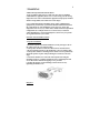
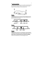
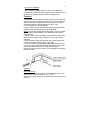
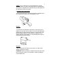
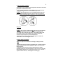
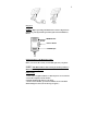
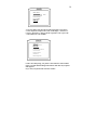
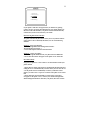
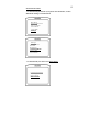
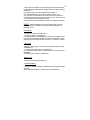
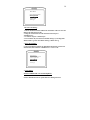
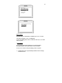
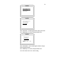
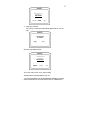
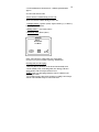
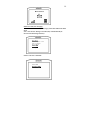
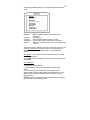
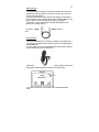
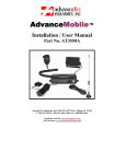
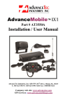
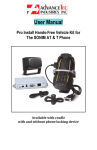
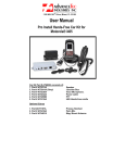
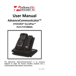
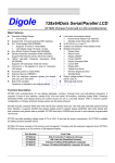
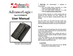
1
AdvanceBlue™
Installation and User Manual
Bluetooth Car kit
Part No. AT8000A
1150 NW 163rd Drive, Miami, FL 33169
Tel: (305)623-3939 Fax: (305)623-3996
www.advancetec.com
2
Menu
•Car Kit Part Numbers and optional extras
•Warnings
•Speaker Installation Instructions
•Junction Box Installation
•Power Cable Installation
•Entertainment Mute
•Mounting of Control Module
•Microphone Installation
•Display Monitor Installation
•Control Module Detail
•Pairing the Phone to Bluetooth
•Disconnecting Bluetooth
•Reconnecting Phone
•Phone Book Download
•Receiving a Call
•Call Waiting
•Making a Call
•Manually Dialing
•Recent Call Dialed
•Phone Book Dialing
•Voice Dialing
•Speed Dial & Set up
•Advance Features during Call
•SMS (Text Messaging)
•Additional Phone Settings
•Reset System
•Power Disconnect
•Rapid Charging
•Privacy Handset
•Specifications
Page 3
Page 4
Page 4
Page 4
Page 5 - 6
Page 6
Page 6
Page 7 - 8
Page 8
Page 9
Page 9 - 10
Page 10
Page 11
Page 11 - 12
Page 13
Page 13
Page 13
Page 13
Page 14
Page 14
Page 15 – 17
Page 17 – 18
Page 18
Page 19
Page 20
Page 20
Page 20
Page 21
Page 22
3
The Bluetooth Wireless Car Kit (Model # AT8000A) includes:
1. AT8010A
2. AT8011A
3. AT8012A
4. AT8013A
5. AT8243A
6. AT8230A
7. AT8229A
8. AT8231A
9. AT8232A
LCD Display
Mounting Post with suction cup
4 Piece mounting bracket
Control Module
Junction Box
Visor Microphone
Visor Microphone
Speaker
DC Power cable
Optional Extras
1. AT8110A
2. AT8111A
3. AT7107A
Mini USB Rapid Charging cable
Micro USB Rapid charging cable
Privacy Handset with Cradle
Note! A properly installed Hands-free Car Kit will minimize service calls
and equipment downtime. Because of the wide variations in vehicle design,
these instructions should be modified to suit each particular installation.
Before beginning the installation process, determine the locations for the
mounting of the LCD Display, Mounting Post with suction cup, Control
Module, Visor microphone, Speaker and Junction box.
Consider the following guideline when planning the installation:
•
•
•
•
•
•
•
•
DO use all mounting hardware provided.
DO ensure that cables are not placed under stress.
DO follow proper + and - connections.
DO crimp connectors securely.
DO NOT attach components to any part of the vehicle that is not
rigid or is subject to excessive vibration.
DO NOT install components in areas where rain or snow can
easily get into them, such as next to a vehicle window, which may
be left open.
DO NOT pass cables over sharp edges that could cause wear or
tearing of cable insulation.
DO NOT install components in locations where they might
interfere with the vehicle operator or operating controls.
4
! WARNING
VEHICLES EQUIPPED WITH AIR BAGS
An air bag inflates with great force. DO NOT place objects, including
communications equipment, in the area over the air bag or in the air bag
deployment area. If the communication equipment is improperly installed
and the air bag inflates, this could cause serious injury.
It is recommended that the installation of the vehicle communication
equipment be performed by a professional installer/technician trained in
the requirements for such installations. An air bag's size, shape and
deployment area can vary by vehicle make, model, and front compartment
configuration (for example, bench seat vs. bucket seats). Contact the
vehicle manufacturer's corporate headquarters, if necessary, for specific
air bag information for your vehicle.
INSTALLATION INSTRUCTIONS
A. Speaker Installation
1. Mount the Speaker beneath the dashboard, on the passenger's side of
the vehicle out of the way of the passenger.
2. The Speaker should be located more than four feet from the driver.
3. Do not mount the Speaker on the dashboard or the rear window shelf.
4. The Speaker includes a mounting bracket which is used to permanently
mount the Speaker in place while permitting it to be tilted to a desired
angle.
5. Loosen the thumbscrews on the side of the Speaker and using the
mounting bracket as a template, drill the necessary mounting holes and
secure the bracket with the self-tapping screws provided.
6. Position the Speaker on the mounting bracket and secure it by
tightening the thumbscrews.
Diagram 1
5
B. Junction Box Installation
1. Mount the Junction Box with the screws provided to permanently install
the Junction Box beneath the dashboard on the passenger's side of the
vehicle or on the center side post, between the front seats.
Diagram 2
2. The Junction Box must be protected from dirt and moisture and must
be afforded adequate space for cooling. There must be sufficient space to
allow for connection of all cabling.
Visor Speaker
Microphone
Display
Monitor
Privacy Power
Handset Jack
Diagram 3
Diagram 4
Rapid
Charger
Control
Module
Hardware
Upgrade
3. Route the cables out of the way to avoid physical or visual obstruction.
Allow sufficient slack in the cable to allow smooth operation of all controls.
4. Connect the Control Module, Speaker, Visor Microphone, Display
Monitor and Power cable connectors to their respective corresponding
connectors in the Junction Box, as shown in Diagram 3 above.
6
C. Power Cable installation
1. Route the black lead of the main power cable to convenient chassis
ground and the red lead to the positive supply voltage connection points. If
it is necessary to penetrate the firewall, use an existing opening.
Caution!
1. The Hands-free unit should be used with a negative ground system only.
2. If necessary, drill a new hole approximately 9/16” (3.5cm) in diameter.
Make sure that there is enough clearance on the opposite side. Insert a
grommet into the hole to prevent damage to the power cable.
3. Cut the black lead to the desired length.
4. If the connection is being made under the dash or in the vehicle cabin,
connect the black lead directly to the chassis of the vehicle..
Note! Do not connect the black lead to the negative (-) battery terminal.
The car could be damaged if there were a malfunction in the vehicle’s
electrical system.
5. Cut the red lead to the desired length. This lead will be connected such
that it has positive supply voltage at all times, even when the vehicle is
turned off.
6. If the connection is being made under the dash or in the vehicle cabin,
connect the red lead to a positive supply voltage point.
7. If the connection is being made in the engine compartment or directly
to the battery, connect the in-line fuse holder between the red lead of the
power cable and the desired positive voltage connection point.
8. Route and connect the green lead to a convenient ignition switch supply
point in the vehicle.
Diagram 5
Entertainment Mute
If the vehicle’s stereo system supports an external muting feature, route
and connect the orange wire to the car stereo system.
Otherwise, the orange wire may be left unconnected and cut off or tied out
of the way.
7
NOTE! The Car Kit supports an “Entertainment Mute” function
when connected to a car stereo system that provides for external muting.
This function is compatible with systems that mute the audio output when
the control line is connected to ground
D. Mounting of the Control Module
1. The Control Module can be attached to the gear lever, parking break or
other similar devise with the Velcro strip supplied as shown.
Diagram 6
2. To attach the Control Module to a flat surface, remove the Velcro by
pulling on one end of the Velcro to slide it out. Screw the flat ribbed plate
supplied with the Control Module in position in a convenient place (with
the ribs facing up) within easy reach of the driver, using the 2 screws
supplied. Align the Control Module over the ribbed flat plastic and press
down until it snaps firmly into place.
Diagram 7
3. Once attached, pass the surplus cord out of the way so that it is not
visually or physically obstructive.
Caution!
Make sure that there is sufficient slack in the cable to allow
the free movement of what ever it is attached to, without stretching the
Control Module cable.
8
E. The Microphone installation
Selecting the correct position for the microphone is vital for the successful
performance of the hands-free unit.
1. The Microphone should be mounted either on the sun visor directly
above, and facing, the driver or on the headliner just above.
NOTE! The microphone has a noise cancellation function and so the
point as indicated in Diagram 8 below must face directly towards the
driver. If it does not face the driver, the driver’s voice will not be heard.
Diagram 8
NOTE! The car kit is supplied with one of the above two microphones.
They are both designed for the car kit and both work equally well
2. To avoid visual or physical obstruction, route the microphone cable
down inside the door frame molding. Allow sufficient slack in the
connector end of the cable to reach the Junction Box.
3. Plug the connector side of the external microphone cord into the
Junction Box as shown in diagram 3 above.
F. Display Monitor Installation
Note: Two options are included for mounting the Display Monitor
1. Slide the flat end of the suction cup mounting post or the flat end of the
flexible mounting bracket (both supplied) into place on the back of the
Display Monitor.
2. Attach the suction cup onto the front wind shield or the flexible
mounting bracket in a convenient position, (as the case may be) ensuring
that the Display Monitor does not obstruct the drivers view. Dress the
surplus cord out of the way. See Diagram 9 over the page.
9
Diagram 9
NOTE: Before operating the Bluetooth car kit it is important to
familiarize yourself with the operation of the Control Module as
shown.
SEND/Answer
Scroll
Push to Select
END/Escape
Pairing the phone to the Bluetooth Car Kit.
Before you can use this car kit, you must link (pair) it to your phone.
NOTE! This Bluetooth Car Kit can only be used if you have a
Bluetooth enabled phone.
Initial Pairing
1. Turn on the car ignition and the Car Kit will power on. The software
version will be displayed on the monitor.
2. Enable the Bluetooth mode on your phone.
3. On the Control Module, press the Scroll Wheel to select the Main
Menu/Settings/New Pair (wait for message to appear.)
10
Main Menu
Voice & Speed
Call Log & Dial
Phone Book
Inbox SMS
Settings
Dial
4. On your phone, select the relevant option to look for a new device.
5. After the phone completes the search, it will display “AdvanceTec”
6. Select “AdvanceTec” and you will be requested to enter a pass code.
7. The default Pass Code is”8888”.
Settings
Paired Phones
New Pair
Brightness
Load Phone Book
Volume Set
Phone Mode
Software
Reset System
8. After successful paring, your phone’s name will show on the monitor.
If not, go to Main Menu/Settings/Paired Phones and check if your phone
name appears.
If yes, select your phone name and select connect.
11
1. Motorola
2. Blackberry
>> iPHONE
4 Nokia
5. Samsung
If your phone’s name does not appear then you should retry pairing.
9. Once you have set up the paired link between your phone and the Car
Kit, the Car Kit will remember your phone’s ID and will automatically
connect when you next enter and start your vehicle.
Disconnecting Bluetooth connection
The phone automatically disconnects when you are beyond the 10 meter
range of the car kit. To manually disconnect, use one of the following
methods:
Method 1: (Using your Monitor)
1. Scroll through Main Menu/Settings/Paired Phones.
The Paired phone is marked >>
2. Select Paired phone and then select Disconnect.
Method 2: (Using your phone)
1. Scroll through the Main Menu of your phone and select Bluetooth.
2. Set to OFF. Disconnect will appear on the phone screen. Select OK.
Re-Connect Phone
Program your phone for “Auto Connect”. For this function consult your
phone manual.
1 .If the phone is already paired and was not manually disconnected when
exiting the car, it will automatically reconnect when you next enter the car.
2. If the phone does not automatically reconnect, (a function of some
phones) you will receive a request to reconnect on the phone screen. Select
OK.
3. If the phone does not automatically reconnect and a request does
not appear on the phone screen, scroll on your monitor through Main
Menu/Settings/Paired Phones and select your phone, then select connect.
12
Phone Book Download
1. To download the phonebook of your phone onto the Monitor, scroll to
Main Menu/ Settings/ Load Phonebook.
Main Menu
Voice & Speed Dial
Call Log & Dial
Phone Book
Inbox SMS
Settings
Settings
Paired Phones
New Pair
Brightness
Load Phone Book
Volume Set
Phone Mode
1. To download all your entries select Sim & Phone
Load Phone Book
Sim Only
Phone Only
Sim & Phone
13
2. Select Start. The number of entries loading will count until all entries
are downloaded. The final number showing will be the number of entries
downloaded.
Up to 1000 contacts can be downloaded for pair number 1.
Up to 1000 additional contacts are shared between the users 2-5.
3. If 2 or more users share the same car kit, then user 2-5 will have to
reload their phone book each time they wish to access it. The car kit will
save the phone book of the last phone paired.
4. Select Cancel to stop download if no activity was noted after 1 Minute
NOTE: If the downloading process starts and then stops, this is an
indication that the Car Kit does not support this function with your
particular phone.
Receiving call
1. To answer a call press “SEND/Answer”
2. To reject a call press “END/Escape”
3. Caller ID will show on the display if the caller’s name and phone # has
been entered in the Monitor phonebook. If the name and phone # of the
caller has not been entered, the caller’s phone # or “Unknown” will show.
Call Waiting
1. During a call in progress you can accept an incoming call by pressing
“SEND/Answer”
2. To reject an in coming call press “END/Escape”
3. To scroll between 2 calls press “SEND/Answer” The active call will be
highlighted.
4. To end an active call press “END/Escape”
Making a call.
A call can be made in the following ways:
1. Manually Dialing:
1. Use the Scroll Wheel to display the Main Menu/Call Log & Dial / Dial
and select.
2. Select the desired numbers to dial and press “SEND/Answer”
14
Main Menu
Voice & Speed Dial
Call Log & Dial
Phone Book
Inbox SMS
Settings
2. Recent Calls Dialing:
1. The last 10 Dialed and last 10 Received call numbers will be saved to the
Dialed Calls and Received Calls
2. Using the Scroll Wheel select the desired location and press
“SEND/Answer“.
3. To end the call press “END/Escape”.
4. You can delete all your Received or Dialed call logs by selecting Main
Menu/Call & Log. Then select Delete Out log or Delete In Log.
3. Phone Book Dialing:
Use the Scroll Wheel to display the Main Menu/Phone Book. Scroll to the
desired Name, Select then use “SEND/Answer” to start a call.
Main Menu
Voice & Speed Dial
Call Log & Dial
Phone Book
In Box SMS
Settings
4. Voice Dialing:
ONLY available with voice activated phones
Scroll to Main Menu/Voice & Speed Dial/Voice Dialing and select.
15
Main Menu
Voice & Speed Dial
Call Log & Dial
Phone Book
Inbox SMS
Settings
Voice and Speed Dialing
Voice Dialing
Speed Dialing
Speed Edit
Shortcut option:
From idle state press and hold down “END/Escape” key for 3 seconds.
You will be prompted to “SAY A COMMAND”
Use the voice dialing feature of the Car Kit in the same way as you would
with your phone.
5. Speed Dialing:
The Speed Dial facility holds 28 numbers for each paired phone.
Five different phones can be paired to the car kit at one time.
To enter a New Contact to the speed dialing you have 2 options:
1.
In Main Menu/Voice & Speed Dial/Speed Edit. Scroll to an Empty
location and select.
16
Voice & Speed Dial
Voice Dialing
Speed Dialing
Speed Edit
Voice & Speed Dial
Voice Dialing
Speed Dialing
Speed Edit
Select “Edit Name”, scroll through the letters and type the name.
Press “END/Escape” to return to the Speed Edit Screen.
Edit Speed .01
Joe Moore
Edit Number
PASTE
SAVE
DEL
Select “Edit Number”, and scroll through the numbers and type
the desired phone number.
Press “END/Escape” to return to the Speed Edit Screen.
To save the contact select “Save” before exiting.
17
Edit Speed .01
Joe Moore
Edit Number
PASTE
SAVE
DEL
2. Using Copy and Paste.
You can copy a contact from Phone Book, Dialed Calls or received
Calls.
305 555 5555
Joe Moore
Copy
SEND
Paste it in a speed dial location.
Edit Speed .01
Joe Moore
Edit Number
PASTE
SAVE
DEL
To save the contact, select “Save” before exiting.
To Dial from the Speed Dial memory you can:
1. Scroll to Main Menu/Voice & Speed Dial/Speed Dialing. Scroll to the
desire location and press the scroll wheel to select or “SEND/Answer”
18
2. Push and hold down “SEND/Answer “ until the Speed dial menu
appears.
Press the scroll wheel to Select.
Advance Features available during an active call
There are 3 features available during an active call
1. Changing Volume. (Speaker symbol) Adjust volume Up (+) or Down (-)
by rotating the Scroll Wheel
2. Dialing numbers ( key board symbol )
3. Phonebook access (Book symbol )
Talking
305 555 5555
Joe Moore
Select each of the above options using your control wheel.
Go back to your previews option by pressing “END/Escape”.
Incoming SMS (Text Messaging)
1. Once the phone is paired the car kit will be in the Stand By mode.
2. In the Stand By mode, an incoming SMS (Text Message) will show
on the Monitor with an envelope and down arrow.
NOTE: SMS (Text Messaging) function is only be available if your
phone supports SMS
3. To read the message, click on the envelope by scrolling to the envelope
with the control module and press on the scroll wheel
19
Motorola Phone
Old & New SMS (text messaging)
To read an Old or New SMS (text messages) select Inbox SMS on the main
menu
Note: Once the New Messages are loaded, they will automatically be
moved to the Old messages directory.
Main Menu
Voice & Speed
Call Log & Dial
Phone Book
Inbox SMS
Settings
Select to read New or Old SMS
Inbox SMS
Read New SMS
Read Old SMS
Dial
20
The following additional settings are accessible through the SETTINGS
menu:
Settings
Paired Phones
New Pair
Brightness
Load Phone Book
Volume Set
Phone Mode
Software
Languages
Reset System
Brightness
Volume Set
Languages
Phone Mode
Software
Monitor brightness settings from 0 -100% in 10%
increments
Adjust from 0 – 7
Choose English, Spanish, German or French
If some features do not work in Mode 0, try Mode 1.
This is only needed when there has been an upgrade of the
software.
The upgrade will be provided by AdvanceTec either in the form of a CD or
on the www.advancetec.com website. Software can be upgraded via a
standard USB connector to the Junction Box or a mini USB to the
Monitor.
Reset System
This will reset the main board in the same way as after
the unit is powered ON.
The resetting of the system will have the same effect as powering the unit
ON and OFF.
Power disconnect
If the ignition is turned OFF and:
1. a call is in progress, the car kit will remain ON until the call is
ended.
2. a call is not in progress, a count down timer will show on the
monitor display showing the time until the car kit will turn off. To add
additional time to delay the turning off, click on the timer icon with
the Scroll Wheel
NOTE: When the car kit is OFF, the pressing of END/Escape will turn
the car kit ON even if the ignition is OFF
21
Rapid Charging
1. To rapid charge your phone you will need to purchase the AdvanceTec
rapid charger cable that matches your phone. Consult your sales person
for the correct part number.
2. Plug the USB connector of the cable into the USB port on the junction
box (See diagram 3 above) and the Mini or Micro USB (depending on your
phone) connector on the other end of the cable into your phone
3. The battery symbol on the monitor will blink, indicating that your
phone battery is being charged.
To Junction
Box
To Phone
Privacy Handset
1. The Privacy Handset Part # AT7107A is available as an optional extra
2. Plug the privacy handset RJ45 connector into the corresponding plug as
shown in Diagram 3.
3. To have a private conversation lift the handset and the audio will switch
from the hands-free speaker to the handset.
4. When the handset is lifted an icon will flash in the right top corner of the
display monitor indicating that the handset is out of the cradle
Talking
305-555-1212
5. To resume a hands-free conversation, replace the handset into the
cradle.
22
Specifications
Electrical Specifications
1. Power input : 12VDC-24VDC
2. Operating temp:-20 ~+70
3. Storage temperature -30 ~+80
Charging
Output: 5V, 450mA with the AdvanceTec charging cable
5V , 100mA with a regular USB cable
Audio Specifications
1. 10W loudspeaker
2. Full duplex audio digital transmission
3. Noise suppressions écho cancellation DSP
Bluetooth Specification
1. Bluetooth 2.0+EDR
2. Tx Power: Bluetooth Class 2.
3. Frequency Band: 2.4G
4. Supports:
a. Hands-free (HFP),
b. Headset (HSP),
c. Phonebook Access (PBAP ) profiles.
d. Supports SMS ( with some of phones )
LCD Specifications.
1. Outside Dimensions : 103mm(L)*103mm(W)
2. Display font size: 6.09 mm
3. Format: 128x64dots
4. LCD mode: STN /Negative transmissive /Blue Mode
5. Viewing direction: 6 o’clock
6. Backlight color: Side White
7. Viewing area: 62.0mm(L)*44.0mm(W)
8. Dot size: 0.40mm(L)*0.56mm(W)
1150 NW 163rd Drive, Miami, FL 33169
Tel: (305)623-3939 Fax: (305)623-3996