1
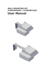
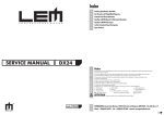
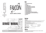
Index 2 3 4 5 6 7 8 9 10 11 12 13 14 15 16 17 18 19 Opening & Keyboard Disassembling Instructions Cabinet Assembly & Wiring Connections Panel & Keyboard Assemblies & Wiring Connections Block Diagram & Wiring Connections Power Amplifier & Supply, Crossover, Phones and Midi & Controls I/O Schematics Power Amplifier & Supply, Crossover, Phones and Midi & Controls I/O Pcb Layouts L & R Controls Panel and Controls Panel Interface, Sliders and Pitch Schematics L & R Controls Panel and Controls Panel Interface, Sliders and Pitch Pcb Layout L & R Contacts and Keyboard Interface, Dc-Ac Converter Schematics, RS232-422 Cabling Timing Table & Adjustment Table Cpu & Sound Generator Schematic (Part 1/2) Cpu & Sound Generator Schematic (Part 2/2) Cpu & Sound Generator Pcb Layout Cpu & Sound Generator Map A/V & Vocal Processor Schematic A/V & Vocal Processor Pcb Layout, AUTOTEST Procedure and Adjustment Frequently Asked Questions Spare Part List Warnings ✔ ✔ ✔ SERVICE MANUAL Notice Service must be carried out by qualified personnel only. Any tampering carried out by unqualified personnel during the guarantee period will forfeit the right to guarantee. For a correct operation of the instrument, after having switched off, be careful to wait at least 3 seconds before switching on again. To improve the device's specifications, the schematic diagrams may be subject to change without prior notice. All components marked by this symbol have special safety characteristics, when replacing any of these components use only ✔ ✔ ✔ ✔ ✔ ✔ ✔ ✔ ✔ manufacturer's specified parts. The (µ) micro symbol of capacitance value is substituted by U. The (Ω) omega symbol of resistance value is substituted by E. The electrolytic capacitors are 25Vdc rated voltage unless otherwise specified. All resistors are 1/8W unless otherwise specified. All switches shown in the "OFF" position. All DC voltages measured to ground with a voltmeter 20KOhm/V. Soldering point. Supply voltage. Logic supply ground. Test point. Analog supply ground. Male connector. Female connector. M/F faston connector. ATTENTION Flag joined with one or more flags with the same signal name inscribed. Chassis ground. Earth ground. Observe precautions when handling electrostatic sensitive devices. Address CODE: 270236 ✒ ☎ GENERALMUSIC S.p.A. Sales Division: 47842 S.Giovanni in Marignano (RN) ITALY - Via delle Rose, 12 Phone +39(0)541/959511 - Fax +39(0)541/957404 - GENERALMUSIC on the NET: http://www.generalmusic.com 1❏ 1) Opening Instructions: 1) Opening Instructions: Disconnect the instrument from the mains. Lift the cover and unscrew the screws (A), these are 3 screws on GPS2600 model and 2 on GPS3600 model. Remove the protection panel by lifting it from the rear (B). On GPS3600 only remove the front panel also: to do this unscrew the two lateral screws (C) which lock it to the chassis, pull it toward you and lift it up; the keyboard cover must be pulled down. To easy access to the internal circuitry, you must remove the controls panel. Unscrew the three screws (A), disconnect all the jumpers, pull the controls panel toward you and raise it. B Note: Place two sheets of paper between controls panel and the flanks to avoid their scoring. A PS2600 only A C PS3600 only 3) Only on GPS3600 to remove the keyboard cover unscrew the four screws on the arms (two for each side), then pull out the cover. 4) To remove a key insert a screwdriver or similar tool in the split at the key back, apply a light pressure and push in the direction shown. Before removing a natural key you must remove the keyboard, removing a sharp key this operation is not necessary. weight TP21 TP23 IMPORTANT NOTICE: Starts from july 2000 the GPS2600 and GPS3600 models are manufactured with a new type of keyboard (TP23), it may be recognizable from first versions (TP21) by means the weight applied at the key front end in the first type (TP21) only. Also the first type of piano are recognizable from the second by the code imprinted on the product label: 991207, 991208, 991223, 991224, 991225, 991226, 991227, 991228, 991229, 991230, 991231, 991232 identify the first versions (TP21 keyboard), while: 991279, 991280, 991281, 991282, 991283, 991284, 991285, 991286, 991287, 991289, 991290 identify the second versions (TP23 keyboard). ❏2 DRW BOCCATO DWG: 550201 PCB# GENERALMUSIC S.p.A. ITALY CKD BATTELLI DSK: 6 PRT: 1/1 APP. PANNELLI REV: 10/07/00 GPS2600-3600 Opening Instructions & Keyboard disassembling ALL RIGHTS ARE RESERVED, NO COPIES OR REPRODUCE THIS DOCUMENT WITHOUT WRITTEN CONSENT BY GENERALMUSIC. This drawing reproduce GPS2600 assembly only. Most part of GPS3600 model are the same or similar. 43/44 42 31 41 40 1 39 CN1 2 CN2 38 Pcb#315103/1 CN4 CN3 CN2 Pcb#310651 CN11 to display CN1 CN1 CN4 CN2 CN10 3 5 4 6 Pcb#315103/1 CN3 CN1 CN4 37 to controls CN9 CN12 CN1 CN3 CN4 CN2 36 35 Pcb#315102/2 CN2 CN6 CN7 CN5 CN1 CN16 CN2 SIMM17 SIMM18 Pcb#315092/1 VR2 to controls panel interface board CN7 CN6 CN9 CN7 CN3 7 CN8 CN5 CN4 CN8 CN10 CN3 CN15 CN11 8 VR1 CN13 Pcb#315150/1 to Keyb. Interface Board CN6 to Keyb. Int. B. CN7 6 9 34 10/11 12 13 14 Lcd Contrast adjust 15 16 17 18 19 20 21 22 23 24 25 26 27 28 29 30 Aftertouch adjust 32 33 DRW G.Boccato DWG# 550199 PCB# GENERALMUSIC S.p.A. ITALY CKD I.Battelli DISK: 6 PRT: 1/2 APP. M.Galanti REV: 04/07/00 PS2600 Internal Assembly for descriptions and codes see REF column on Spare Part List further on this manual. ALL RIGHTS ARE RESERVED, NO COPIES OR REPRODUCE THIS DOCUMENT WITHOUT WRITTEN CONSENT BY GENERALMUSIC. 3❏ Pitch Bender adjustment 46 45 47 48 50 49 51 52 53/54 55 56 57 from Cpu & Sound Gen. Board CN1 58 CN4 59 60 61 CN1 Lcd Display Pcb#315104 Pcb#315184 Pcb#315100 Red Brown CN2 CN3 Pcb#CS032001 CN4 CN3 CN5 CN2 CN3 CN5 CN1 CN2 Pcb# 315105 CN1 CN6 Pcb#315183 CN9 CN7 VR1 from Power Amp & Supply Board CN5 45 62 64 63 65 66 from Cpu & Sound Gen. Board CN2 70 67 68/69 71/72 73 74 75 61 Black Rotate from full counterclockwise to this position aligned with centre pin. Insert the wheel with groove at centre. Adjust VR1 as described in Autotest procedure. 76 79 78 CN1 CN2 CN1 81 80 CN4 Pcb#315024 Pcb#315187 CN1 Natural Key Aftertouch Strip 77 CN1 CN3 CN6 Pcb#310531 CN2 CN2 CN2 CN7 Pcb#310530 from Cpu & Sound Gen. Board CN11 from Cpu & Sound Gen. Board CN15 This drawing reproduce GPS2600 assembly only. Most part of GPS3600 model are the same or similar. ❏4 Sharp Key Aftertouch Strip 13 DRW G. Boccato DWG: 550200 PCB# GENERALMUSIC S.p.A. ITALY CKD I.Battelli DSK: 6 PRT: 1/1 APP. R.MORBIDI REV: 07/07/00 GPS2600 Controls Panel & Keyboard Assembly for descriptions see REF column on Spare Part List further on this manual. ALL RIGHTS ARE RESERVED, NO COPIES OR REPRODUCE THIS DOCUMENT WITHOUT WRITTEN CONSENT BY GENERALMUSIC. DRW Boccato DWG# 550195 PCB# GENERALMUSIC S.p.A. ITALY CKD Battelli DISK: 6 PRT: 1/1 PS2600-GPS2600-GPS3600 BLOCK & WIRING DIAGRAM APP. Pannelli REV: 20/02/2000 ALL RIGHTS ARE RESERVED, NO COPIES OR REPRODUCE THIS DOCUMENT WITHOUT WRITTEN CONSENT BY GENERALMUSIC. 5❏ ❏6 CROSSOVER BOARD (PCB# 310651) POWER AMPLIFIER & SUPPLY BOARD (PCB# 315102/2) CONTROLS & MIDI I/O BOARD (PCB# 315103/1) PHONES BOARD (PCB# 310513) DRW: BOCCATO DWG: 315102,315103 310651, 310513 CKD: BATTELLI DISK: 6 PART: 1/1 APP: PANNELLI REV: 08-03-00 SCHEMATIC DIAGRAM PS2600 GPS2600-3600 Power Amplifier & Supply, Crossover, Controls & MIDI I/O and Phones Boards GENERALMUSIC S.p.A. Italy ALL RIGHTS ARE RESERVED, NO COPIES OR REPRODUCE THIS DOCUMENT WITHOUT WRITTEN CONSENT BY GENERALMUSIC. 7❏ ❏8 CONTROLS PANEL INTERFACE BOARD (PCB# 315183) RIGHT CONTROLS PANEL BOARD (PCB# 315100) reverse layout KEYBOARD INTERFACE BOARD (PCB# 315024) LEFT CONTROLS PANEL BOARD (PCB# 315184) reverse layout SLIDERS BOARD (PCB# 315104) reverse layout DRW: BOCCATO DWG: 315100,315104 315183, 315184 CKD: BATTELLI DISK: 6 PART: 1/1 APP: PANNELLI REV: 08-03-00 SCHEMATIC DIAGRAM PS2600 GPS2600-3600 L & R Controls Panel, Sliders, Interface & Keyboard Interface Boards GENERALMUSIC S.p.A. Italy ALL RIGHTS ARE RESERVED, NO COPIES OR REPRODUCE THIS DOCUMENT WITHOUT WRITTEN CONSENT BY GENERALMUSIC. 9❏ ❏ 10 11 ❏ ❏ 12 13 ❏ CPU & SOUND GENERATOR BOARD (PCB# 315150/1) DRW: BOCCATO ❏ 14 DWG: 315150/1 CKD: BATTELLI DISK: 6 PART: 1/1 APP: PANNELLI REV: 08-03-00 SCHEMATIC DIAGRAM PS2600 GPS2600-3600 Cpu & Sound Generator Board GENERALMUSIC S.p.A. Italy ALL RIGHTS ARE RESERVED, NO COPIES OR REPRODUCE THIS DOCUMENT WITHOUT WRITTEN CONSENT BY GENERALMUSIC. CN2 - to Controls Panel Board J1 - Set the jumper as follow: 1-2 "A" if Buffer modules are installed 2-3 "B" if SIMM DRAM modules are installed note: the buffer modules are supplied with A/V & Vocal processor kit, if neither buffer or Simm modules are installed, J1 position is ininfluent. CN3 - to MIDI I/O Board CN1 or CN17 to Lcd Display (depend by organ model) CN4 & CN12 to A/V & Vocal Processor Board LCD PANEL CN1 MIDI CN2 CN3 CN5 - SAMPLE DRAM Expansion Two sizes are available: 970213 - 2Mbyte (32pins) 970331 - 8Mbyte (44pins) 45.15MHz 8MB DRAM CN12 CN17 CN4 LCD VIDEO CN6 - to Outputs or Amplifier Board J2 - Set this jumper as follow: 1-2 for 8MB SAMPLE DRAM expansion 2-3 for 2MB SAMPLE DRAM expansion if no DRAM expansion is installed the jumper position must be 1-2. Ground Connection CN6 ANALOG OUTPUTS DISP3 CN16 - SCSI Expansion DRAM SCSI SIMM J1 B 2MB 315150 CN7 - from Power Supply Board POWER SUPPLY A FLASH MEMORY 2MB DRAM 8MB J2 FLASH MEMORY 8MB CN5 CN16 CN8 - HARD DISK Expansion 970207 - Optional mounting kit for Hard disk unit SIMM17 SIMM18 HARD DISK CN7 CN10 CN8 DRIVER 2MB DRAM CN9 SIMM DRAM Expansion Slots, These modules must be two as: 1M x8 or x9 70nS 30-pins 4M x8 or x9 70nS 30-pins only 4Mx2 are available from Generalmusic as code 970225 CPU FLOPPY DISK CNTRL FPGA CN10 - to 3.5" Disk Drive KBD KBD SUPPLY CN11 CN13 1 CN13B VIDEO CN14 CN15 CN11 - to Keyboard Interface Board CN9 - 2Mbyte DRAM expansion supplied with Hard Disk mounting kit CN13 (and also CN18) - these connectors are connected to A/V and Vocal Processor Board the configuration of these depend by organ model VR1 - After Touch Adjustment CN15 - from Keyboard Interface Board CN14 - Used only for development DRW G.Boccato DWG# 550147 PCB# GENERALMUSIC S.p.A. ITALY CKD N.Riccobelli DISK: 64 PRT: 1/1 Cpu & Sound Generator Board General User Map APP. Orsetti REV: 07/04/98 ALL RIGHTS ARE RESERVED, NO COPIES OR REPRODUCE THIS DOCUMENT WITHOUT WRITTEN CONSENT BY GENERALMUSIC. 15 ❏ 54 8 7 36 P4 V5 53 6 5 37 P5 V6 52 4 3 38 P6 V7 51 2 1 39 P7 PXCLK 41 40 PCLK BLNC 60 3 104 5 2 4 33E X4 2 3 +5V 8 1 1 7 IC9-A AR2 33E X4 3 2 74HC00 2 10 1 3 IC2-A 5 Q 8 IC3-C 9 74HC74 CK 3 D FF 6 Q 74HC125D S D 2 R +5V 1 100N 10U 15 27 6 22 21 -18V 7 8 D FF D R 13 Q 8 D FF R 1 Q 6 S 4 +5V 22N 12 2 D 1U C23 CK 2 LGND 74HC74 Q 9 C22 390E IC8-B 11 R4 2K2 R10 CN5 33E C32 10U C31 100N VinR VrefR TAG RDEDGE MSBDLY RLJUST S/M 384/256 14 VrefL 10 VinL CAPR1 18 C29 17 C33 CAPR2 470P FL2 50 DT0 51 52 470P RST 23 26 CLK CAPL1 11 C24 470P 12 C25 470P CAPL2 81 82 83 2 1 AR12 13 84 D9 D10 85 D11 86 4 3 33E X4 14 D1 6 5 15 D2 8 7 17 D3 D12 87 D13 88 2 1 AR14 18 D4 4 3 33E X4 19 D5 D14 89 D15 93 6 5 20 D6 8 7 21 D7 D16 94 D17 95 2 1 AR15 4 3 33E X4 AA15 D18 96 D19 97 6 5 AA16 8 7 35 IRQE 55 DT1/F0 DR1/F1 IRQL0 46 IRQL1 6 WR 8 IOMS 5 6 11 CMS 8 14 PMS 7 37 XT1 16MHZ AA13 AR8-D 33E X4 D8 8 1M A13 8 33E X4 D7 7 R36 AA12 7 D6 4K7 X4 AR1 33E X4 AA11 6 AR8-C 34 SCLK1 4K7 X4 28 AA10 7 5 SCLK0 DMS 4K7 X4 5 8 33 TFS1/IRQ1 10 AR17-C 6 32 60 4 AR7-D PWD 40 PWDACK 42 BGH 24 CLKIN 23 XTAL 26 CLK0UT D20 98 D21 99 D22 100 D23 101 RD 7 BMS 9 AA14 IC12-A 27C4001D A0 12 D0 +5V 1 VPP AA17 R35 33E AA18 +5V +5V 24 OE 5 1 22 CS 6 AR19-A 33E X4 22 1 8 AR19-D 33E X4 7 AA1 A3 9 A4 8 AA3 A5 7 A6 6 AA5 A7 5 A8 27 AA7 A9 26 A10 23 AA9 IC14 7812 IN OUT GND 2 330P 330P 330P 330P 330P VIDEO OUT TO POWER AMP & SUPPLY BOARD CN11 (WK) TO ANALOG I/O BOARD CN11 (SK) TO CONTROLS & MIDI I/O BOARD CN1 (PS-GPS) 1N 1N 120E C91 R63 1N 120E R53 C77 100N C28 100N 8 IC19-B TD8501 10 C79 50V 47U 10U 1N C80 44 C73 21 22 C83 5 2 3 4 20 21 IC21-B ADV476KP35 19 23 24 41 42 43 100N BLM21 3 2 IN 1 GND 3 OUT IC13 7912 1 7 IC15-B TL071 4 14 IC8-C 74HC74 7 32 IC12-B 27C4001D 16 IC7 7805 IN OUT GND 2 13 IC17-B 12 25 L1 3 47UH +5VC 9 4 25 IC6-B AD1877 13 16 20 5 24 28 43 73 91 115 79 90 92 ADSP2181 27 44 58 102 116 127 AA2 AA4 AA6 Adjustment Table UNUSED COMPONENTS AA8 N. AA10 A11 25 AA11 A12 4 AA12 A13 28 AA13 A14 29 AA14 A15 3 AA15 A16 2 AA16 A17 30 AA17 A18 31 AA18 IC20-B 3 +5V IC2-B 11 CK 12 D 74HC74 Q 9 D FF R 13 7 8 Q 8 S 10 5 6 IC9-D 12 Adjustment Type Test Point Operation Point Note: COMPOSITE DUTY CYCLE ADJ R32 side IC18 C81 Set the oscilloscope on DC at 1V/div. 50uS/div., turn the trimmer to have duty cycle more close as possible to 50%, verify the adjustment with a monitor attached to VIDEO OUT socket. 74HC00 11 +5V +5V 1 4 2 1 4 13 2 1 74HC04 3 4 3 6 5 PCB# 315109 S +5V 10 DRW RICCOBELLI DWG# 550137 PCB# 315109 GENERALMUSIC S.p.A. ITALY CKD RICCOBELLI DSK# 6 SCHEMATIC DIAGRAM ALL RIGHTS ARE RESERVED, NO COPIES OR REPRODUCE THIS DOCUMENT WITHOUT WRITTEN CONSENT BY GENERALMUSIC. APP. PANNELLI ❏ 16 20 -12V 14 IC20-G 74HC04 7 AA0 A1 11 A2 10 1 6 IC16-B HM514260 40 35 100N 31 A11 54 8 AR17-D A10 1 A12 14 IC2-C 74HC74 7 +12V +18V 56 3 3 AA9 80 7 5 3 33E X4 D5 4K7 X4 7 4 RFS1/IRQ0 4K7 X4 4 30 57 AR17-B 6 AA8 A9 +5V AR20-D 8 AA7 1 AR13 -18V 45 3 AA6 7 2 78 3 WCLK 2 LRCK 1 BCLK 5 8 29 77 4 1 6 22 A8 D4 4K7 X4 2 Sout 21 A7 D3 AR7-B 1 A6 RFS0 DR0 4 AA5 TFS0 IRQ2 2 AA4 3 33E X4 76 38 3 1 AR4 4 75 53 4K7 X4 2 20 74 5 4K7 X4 19 A5 D2 6 AR20-B AA3 A4 D1 4K7 X4 AR7-A +5V 7 D0 AR7-C 100E C35 9 -18V 74HC74 R11 Q 5 49 8 14 IC9-E 74HC00 7 R37 22N C34 +5VC IC8-A 3 CK FL1 AD1877 SIGMA DELTA A/D CONVERTER 8 +18V 19 C26 R9 390E +18V FL0 48 59 C6 1U IRD 47 A3 18 L4 14 IC10-E 74HC32 7 100N 4 AA2 C4 10N 33E X4 50V 6 CONV-R R2 10E AR3-B IWR AA1 5 C66 74HC125D IC6-A 5 CONV-L 1 DSPCLK IACK 1 IAL 103 4 R3 2K2 4 7 AGND 41 3 7 AR8-A 1 C30 47U A/V INPUT & SUPPLY FROM POWER AMP & SUPPLY BOARD CN5 (WK) CN4 (SK) CN11 (GPS-PS) CLOCK FROM CPU & S.G. BOARD CN12 3 +5V 4 IS AA0 3 33E X4 6 100N +5V 2 4 4 128 1 IC3-A PF7 8 AC2 47P X4 12 PF6 123 33E X4 74HC125D 11 124 AR3-D 74HC00 8 10 AC1 47P X4 CN2 1 LGND 5 3 AR8-B 33E X4 33E PF5 1 AR6 4 17 C5 1U 10 AR3-C 33E X4 6 5 PF4 125 2 16 A2 C43 3 2 R6 1K R7 1K 2 6 R90 74HC32 8 9 IC9-C 1 R8 1K D2 4148 126 15 A1 47UH 100N 9 IC10-C C18 47P 74HC32 11 13 5 R15 33E 5 A0 L3 C76 74HC32 4 12 IC10-D R/W 3 PF2 2 PF3 4 +5VB +5V C103 74HC00 5 +5VA EMS 63 ECLK 65 ELIN 67 5 PF0 4 PF1 113 C102 47P C13 IC9-B O6 9 O7 7 97 10N IAD15 E1 90 C10 105 4 79 14 IC11-E 74HC125D 7 C9 1U IAD14 D31 R5 1K 3 65 14 IC3-E 74HC125D 7 100N IAD13 106 55 104 112 128 100N IAD12 107 D30 49 96 C44 108 D29 O4 11 O5 10 33 23 85 100N D28 6 E3 5 E2 1 73 C64 61 64 C57 62 ERESET IAD9 50 GATEVIDEO 100N RESET IAD11 48 C15 IAD10 109 O1 14 O2 13 O3 12 32 IC18-B 100N 110 D27 3 A2 17 C63 111 D26 A21 16 IC1-B 74AC138 8 C8 100N D25 A20 EBR 69 ELOUT 66 EE 64 100N IAD8 C7 1U IAD7 112 +5V C11 113 D24 6 5 100N D23 74AC138 O0 15 2 C65 IAD6 1 AR5-A 4K7 X4 100N 114 70 BG 72 EBG 71 C37 D22 BR 100N IAD5 +5V GND 3 NC 8 C12 IAD4 117 +5V 100N 118 D21 68 100N D20 EINT C14 IAD3 VCC 2 RST 7 C41 119 5 NC 6 NC 100N D19 33E MAX709 C56 A1 R24 IC4 1 NC 4 NC 100N IAD2 IC1-A 1 A0 2 A1 BMODE 39 MMAP 36 C19 120 A19 +5V IDMA BOOT EPROM BOOT ADSP2181 D18 6 IC3-D 13 IC17-A A2 IC10-B 8 R16 100E IC11-A 74HC125D IAD1 6 7 3 1 IAD0 D1 4148 +5V 2 121 IC10-A 74HC32 PAL ONLY 100N 390E +5V J1 122 2 TR11 BC327 TR10 BC327 PAL/NTSC D17 1 10K 2 VSYNC CS3 5 R74 +5VA +5V D16 4 6 74HC04 HYSYNC R17 A1 6 5 IC20-C SUBCRR 5K6 74HC125D NTSC ONLY 74HC04 10 CSYNC 111 XT3 10K 74HC04 C20 110 R60 IC3-B COMP 29 VS 39 EXTAL XTAL -12V Iref TR4 BC847 8 IC20-D 10U D_DIR 1 2 CSY 31 SUBCRR 106 HS 40 TEST 330E RS0 17 28 6 RD 33E X4 1 IC20-E 11 R79 100N 56P C68 MD_DIR 5 AR9-C BLU 27 RS1 18 WR 9 3 TR6 BC847 74HC04 12 C60 66 16 IC20-F 13 100E +5V 3 RED 25 GRN 26 7 BLK 33E X4 6 VB 35 HB 34 SCAN_EN D31 D30 R78 C55 SCAN_IN D7 15 Vref 31 +5VA 10U 44 AR16-A RD-WR 108 RD-RD 107 +5VA D29 100N CMPR 33E 1 D28 D5 13 D6 14 BLUE +5VA C52 VCOIN 98 33E X4 R77 2 D27 C47 114 AR21 D3 11 D4 12 D26 100N WE3 D25 C17 WE2 102 GREEN D1 9 D2 10 100N 101 1 RED ADV476KP35 D24 D0 8 C101 WE1 3 PAL ONLY 100N WE0 99 CHR 4 LGND 2 3 R81 V4 DTACK RED 5 VSYNC 2 1 3 8 C58 P3 V3 CS 220E C50 35 82E R41 330P 1 82E R40 C69 2 R44 330P P2 LUM 6 C48 34 CVBS 7 82E 330P 3 BLUE 82E R38 C49 4 82E R39 C87 57 2 1 3 R55 TR9 BC857 2 1 GREEN 9 C71 V2 TR7 BC857 HSYNC 10 82E C93 P1 IC21-A 33E X4 7 TR5 BC857 100P 33 AR18 8 3K9 C96 5 R48 NTSC ONLY 100P P0 6 220N C98 32 58 C88 SW2 17 +5VB 220E R52 50V 59 V1 15 FLT 2 47U V0 1K2 2 CN4 R64 C104 MD15 XRST MODE 680E 84 45 11 R46 MD14 MD15 46 43 10K MD13 83 56 115 R47 MD12 82 MD14 R/W 100 +5V 81 MD13 BSTADJ 2 SW1 R72 2 C99 IC20-A 74HC04 100P MD12 21 1K 1K2 C3 100N 100E MD11 220K 1K2 R65 100N R75 MD10 80 R68 R80 +5VB R66 C21 R19 220E R45 C97 2 78 MD11 47 C40 1K8 100N 1 R22 C36 IC15-A TL071 1K 100P C38 100N C67 R32 +5V 3K9 MD9 MD10 A21 42 R76 MD8 220N 19 CVBS 16 NOTCH 18 OSC 23 100N 2K2 10 MD8 76 MD9 77 MD7 C89 CSYNC 6 C U/Q 12 C V/I 50V 3 R23 6 A20 MD6 MD5 24 220N C53 10K 8 A19 9 A20 PAL 30MHz NTSC 30.20979MHz C75 10P R49 220E R31 A19 A21 22P 4K7 R43 COMP DUTY CICLE ADJ 2 6 A16 7 A17 A18 TR8 MPS818 5P2-30P 100K A17 13 C74 R29 120E 4 A14 5 A15 109 C81 100N A11 2 A12 3 A13 MD6 72 MD7 75 100N 100N C95 3 1 100N 4K7 680E R13 C39 127 100N C61 -12V IC11-D 74HC125D 11 12 XT2 D3 BB204G 100N 100N A12 A16 +5V 10 R42 100E PAL 8.867238MHz NTSC 7.15909MHz 100K C62 A10 A15 R21 4 CHROMA SUBCARRIER PLL R30 A9 126 A14 IC11-C 74HC125D 8 9 +12V 1K A8 125 A13 IC11-B 74HC125D +5V 6 5 R28 124 A11 ADSP2181 +5V A9 A10 Y OUT C90 C105 C46 SDMA-C0 1K2 TR2 BC847 3 1 C100 100N SDMA-CK 2 MD4 R56 TR1 BC847 3 1 47U 4 MD4 68 MD5 70 14 TR3 BC847 2 1K2 C54 A7 C OUT 9 G 11 B GND R70 50V 123 20 47U A8 R1 33E MD3 22 YD IN C51 SDMA-IN MD2 YD OUT DELAY LINE AR19-C 33E X4 6 MD2 69 MD3 67 100N L5 TOKO1436 1 IN OUT 3 AR19-B 33E X4 A6 C92 5 Y 7 R 13 1K AR5-B 4K7 X4 122 100N VREF R73 AR20-A 4K7 X4 A5 A7 MD0 MD1 C94 4 AR3-A 33E X4 121 RST OE FH/2 1K A6 8 27 1K TD8501 1K A4 10 R/W LCAS IC19-A 1 -(R-Y) 3 -(B-Y) R57 120 29 4K7 A21 A5 33E X4 R33 MD0 74 MD1 71 A3 1 AR9-A CPU DATA BUS 119 2 MD15 AR5-D 4K7 X4 1 A4 MD14 22P 3 A20 D14 38 UCAS D15 39 C107 5 CS3 14 MD13 28 RAM DAC 7 SDMA-C1 A3 12 9 A2 A19 D13 37 33E X4 R18 680E A18 118 16 RAS 3 AR9-B 47P 11 A1 WR 14 3 AR16-B 4 C27 PAL/NTSC A0 117 13 7 AR16-D 4 1 OF 8 DECODER 13 116 A2 105005 - FPGA (VIDEO MODE) 15 WE1 C1 100P WE0 A1 33E X4 33E X4 8 22P CN1 63 1K RAS 62 UCAS 105 LCAS 103 120E R/WC D15 C70 D14 29 R51 28 D31 +5VB 1K2 1N D30 R54 MD12 C45 A9 MD11 MD10 D4 4148 2 NC 1K8 1 30 R26 D13 1K8 27 R25 D29 MD9 D11 34 D12 36 1K8 A10 NC R27 4 11 10U 3 NT_OUT C78 D12 1N 26 C106 D28 MD8 1K A11 NC R83 6 12 30 C72 100N D11 MD7 D9 32 D10 33 R59 A8 DTACK2 25 NC 1K 5 D27 15 100E R69 A7 A12 R34 1K 8 D10 MD6 R67 7 24 A8 MD5 D7 10 D8 31 AR16-C 33E X4 A6 D26 26 D5 8 D6 9 PAL/NTSC ENCODER A13 A7 AR9-D 33E X4 10 MAD8 95 A6 25 AR5-C 4K7 X4 9 D9 A5 24 47P A5 22 23 33E X4 C2 47P D25 7 C42 A14 5 AR10 8 UNMOUNTED - FUTURE EXPANSION 12 6 82E 11 3 MAD6 93 MAD7 94 82E A4 4 D8 761152 - AUDIO/VIDEO WITH VOCAL PROCESSOR BOARD (NTSC VERSION) MD4 R88 D7 21 MD3 MD2 RESET D6 20 D24 D3 5 D4 7 82E 19 D23 A15 A4 R86 D22 A16 14 A3 22 1K8 A17 16 13 19 1 R84 18 15 A3 A2 7 R71 17 A2 2 MD1 R82 A1 8 MAD4 91 MAD5 92 761143 - AUDIO/VIDEO WITH VOCAL PROCESSOR BOARD (PAL VERSION) MD0 D1 3 D2 4 100E D5 A1 18 R14 D4 18 17 10N 16 D21 IC16-A HM514260 A0 D0 2 16 33E X4 C16 D20 D31 5 AR11 82E D23 20 3 6 82E 22 19 1 4 82E 21 D16 2 MAD2 88 MAD3 89 R85 D3 D24 MAD0 86 MAD1 87 R87 D2 15 R89 14 D19 1K2 D18 D30 R62 D22 24 100E 26 23 R50 25 D17 AR17-A 4K7 X4 D25 GATEVIDEO 47U D1 IC18-A AR20-C 4K7 X4 D0 13 100N 12 D17 C86 D16 D29 C85 D21 28 100E D28 30 27 R61 32 29 D18 100N 31 D26 C84 D19 256K X16 DINAMIC RAM D20 C82 FROM/TO CPU & SOUND GENERATOR BOARD CN13 34 R20 ADC & CONTROL SIGNALS 33 CPU ADDRESS BUS FROM/TO CPU & SOUND GENERATOR BOARD CN4 ADDR & DATA BUS CPU DATA BUS CN3 D27 REV: PART: 1/1 19-01-00 A/V WITH VOCAL PROCESSOR BOARD Test Procedure and Adjustment The procedures that follow must be executed subsequently in the order specified. These procedures are not intended to repair a fault but only to check the correct instrument operations after a repairing execution. Test Instruments þ Dual trace oscilloscope þ Digital Multimeter þ Signal Generator Accessories þ 2 x 4Mbyte SIMM DRAM modules. þ 1 3.5inch Diskette. þ 1 SCSI Kit. þ Read/write SCSI device (ZIP, JAZ, Hard disk etc ). þ RS232 loopback (terminal 1-2 and 3-5 shorted). þ MIDI Cable. To check completely the keyboard are necessaries all the optional accessories installed. Setup Install the optional accessories: the 2 SIMM Volatile DRAM modules and the SCSI kits, insert the diskette into 3.5" disk drive (Not a Operating System Disk). Set the jumper J1 on CPU board at position B. Set the JP1 and JP2 jumpers on Supply or Mixer board at position A. Connect the external SCSI device to the SCSI socket. Plug the RS232 loopback into the socket. Checks and Adjustments þ Display Contrast adjustment To adjust the display contrast turn VR2 on POWER AMPLIFIER AND SUPPLY BOARD with the CONTRAST potentiometer (located on controls panel) at half stroke. Verify the excursion of the CONTRAST potentiometer checking the display readability from all position. þ Aftertouch adjustment To adjust the keyboard aftertouch locate the VR1 trimmer on CPU board, connect the scope CH1 probe tip to its center terminal, probe clip connected at ground, adjust VR1 to obtain an excursion from 0 to 5V every time a note key is pressed with different pressure, or to obtain a better adjustment follow the instructions on ADJUSTMENT TABLE (page 11). þ RS232 check Press EDIT and using the DIAL and ENTER/ESCAPE controls select 1-GENERAL, select 3-COMPUTER, press F8 button to select MODE and set PC1 with cursor keys, press ENTER to confirm. Press ESCAPE 2 times, select 2-MIDI, select COMMON/ARRG.(F5) and set "Common Ch." to 1 using the DIAL, press (F7) to set LOCAL OFF, verify that the keyboard plays thru RS232 by unplugging and re-inserting the RS232 loopback into the socket. þ RS422 check Press ESCAPE, select 1-GENERAL, select 3-COMPUTER, select MODE(F8), set MACINTOSH, press ENTER to confirm, check the 1MHz 5Vpp clock appear on pin 1 of COMPUTER socket (use the second probe tip to do that). þ MIDI check Re-select MODE(F8) and re-set it to OFF, press ENTER to confirm and ESCAPE 2 times, select 2-MIDI and then press F7 2 times (LOCAL ON and OFF: this operation maybe necessary to re-set the normal MIDI communication); connect the MIDI cable between MIDI A IN and MIDI A OUT sockets, verify that the keyboard plays thru MIDI I/O by unplugging and re-inserting the MIDI loopback cable into the socket. page of GENERAL settings. þ Panel Key and Led check Press EDIT, select 1-GENERAL, press F1 (SYSTEM INFO) and F8 the display shows a warning message: press ENTER to continue, select PANEL TEST(a) and then press all the panel buttons checking their operation on display, at the same time every led of pressed button must light up (note: DISK led and EFFECT OFF are not tested). þ Pitch Bender check Rotate the Pitch Bender verifying the excursion displayed, it ranges from 0 to 127 with 64 on center position. A slightly difference may be adjusted by VR1 on CONTROLS PANEL INTERFACE BOARD, major differences may be adjusted repositioning the knob (see page 4). þ Pedals check Pressing SOFT (Pedal 1) and SOSTENUTO (Pedal 2) the display shows 0 or 127, pressing DAMPER (Pedal) the display shows a value that ranges from 0 to 127 continuosly. Press ENTER and ESCAPE simultaneously to return at HARDWARE test menu. þ Memories and Optional Accessories Press ALL PART (F1), the instrument self-test check subsequently the following devices: SIMM modules (F2 Volatile DRAM), 8Mbyte sample dram (F3 Backed DRAM), Internal Hard Disk (F4 HardDisk), 3.5" disk drive (F5 Floppy Disk), Video interface (F6 Video) and SCSI interface (F7 SCSI Test) and marking with Pass all devices checked successfully, with Not Present all devices not attached, with Fault all device defective. Theoretically all test must be passed, if you have a mistake on a device re-check its installation. Pressing G the third Rom Sound (IC10) is checked. Press ENTER, if necessary, to exit. þ Dsp check Insert a stereo Jack plug into PHONES 1 socket. Put MASTER fader at max, turn on the 1KHz test tone pressing HARDWARE SET(C) and measure with the oscilloscope a 4Vpp sinusoidal signal on tip and ring (L an R) of the Jack. Turn off the signal by means HARDWARE SET(C). þ Vocal Processor check Turn off the effects pressing EFFECT OFF. Insert a 20mVpp 1KHz signal into MIC LINE 1 input socket, put INPUT MIC/LINE fader to maximum position and rotate full clockwise GAIN1 potentiometer located on the back panel. With the oscilloscope always connected to PHONES 1 measure a signal approximately of 12-13Vpp. Repeat this test for MIC LINE 2 input. þ Data Hold Turn off the instrument, disconnect the signal cable, wait at least 30 seconds, turn on again and then press EDIT, select 1GENERAL, press F1 (SYSTEM INFO), press (F8), press ENTER and F8 (DATA HOLD) and then wait until the display show PASS. Note: this test checks the RAM connected to CN5 only. Turn off the keyboard and then remove not included SCSI optional kit, replace the SIMM DRAM with the BUFFER modules and finally restore the J1 jumper position to A. þ Reliability & Final Check Before reassembling the instrument and before deliver it to the user, it is a goal verify its reliability: To do that switch it off, or leaving it switched on but operating with greatest caution, carefully shake the boards and connections inside it using an insulated tool (for example the handle of the screwdriver) to find wrong contacts and so on. Turn on the instrument and re-check that it operate correctly, leaving it switched on for a long time and occasionnally launching the Demo sequence (press DEMO and ENTER) or verifing its functionality. þ DATE and TIME set A/V & VOCAL PROCESSOR BOARD (PCB# 315109) DRW: BOCCATO DWG: 315109 CKD: BATTELLI DISK: 6 PART: 1/1 APP: PANNELLI REV: 08-03-00 SCHEMATIC DIAGRAM PS2600 GPS2600-3600 A/V & Vocal Processor Board GENERALMUSIC S.p.A. Italy Go to page 4 and press SET DATE(F1) button, set the day, month and year using the DIAL or numeric keypad, press ENTER; also set the time pressing SET TIME(F2), finally return to the first ALL RIGHTS ARE RESERVED, NO COPIES OR REPRODUCE THIS DOCUMENT WITHOUT WRITTEN CONSENT BY GENERALMUSIC. 17 ❏ rev. 24-07-00 PS2600-GPS2600-GPS3600 FAQ Questions How can I update the Operating System? 1 Or How can I reload the Operating System? Answers The instrument is equipped with Flash Rom so that you can update it with the last operating system containing fixes, updates and new features. These updates can be downloaded directly from our web site at http://upgrade.generalmusic.com/cgi-bin/upgrade/upgrade.cgi. Afterwards copy the OS file downloaded in the diskette, using a preformatted disk from your instrument prevent possible errors, and follow the instructions below: 1- With the instrument turned off, insert the last Operating System disk then turn the instrument on. 2- The display shows "Loading OS-DISK clears ALL MEMORY!! <Enter to load / Escape to abort>". 3- Press ENTER then wait about 3 minutes for the OS loading. 4- The display shows "Loading successful!! <Enter to continue>", then press ENTER. 5- Turn off the instrument and remove the Operating System disk. 6- As you turn the instrument on, keep rotating the DIAL until the display shows "!!WARNING!! Dial on power-up requests Memory Clear!! <Enter to clear / Escape to abort> 7- Press ENTER, you have now completed the update process. As you turn the instrument on, keep rotating the DIAL until the display shows "!!WARNING!! Dial on power-up requests Memory Clear!! <Enter 2 How can I do a complete SYSTEM RESET? to clear / Escape to abort> Then press ENTER. 3 What do the pedals make? 4 Why do the uppermost keys play always sustained? 5 Why do all pedals work in reverse mode? 6 Why does some pedal work in reverse mode? I have replaced the DAMPER pedal 7 potentiometer, how do I let position it correctly? Why does not the instrument respond correctly? Or 8 Why the initial screen shows a different model at the start-up? (after CPU Board replacing only) ❏ 18 On this instrument the pedals are fully programmable by the customer, but if you play with a GRAND PIANO style the three pedals change with the following functions: Vocal On/Off (left pedal): This pedal switch on or off the vocal processor. Sostenuto (centre pedal): This pedal is a switch control pedal (on/off) which sustains the notes of the key currently depressed, all new notes played after having depressed the pedal are not affected, this pedal operates like a grand piano centre pedal. Damper (right pedal): This pedal applies the sustain effect to all notes released. If you release a note after depressing the damper, the note will proceed towards its natural decay according to the type of sound played. The Damper pedal is particularly effective with Piano type sounds, it is controlled by a "Damper Physical Model" patented by Generalmusic. For some piano sounds the notes from E6 to C8 are automatically sustained such as in an acoustic piano. The instrument reads the status of the pedals at the power on and assume this status (normally open or normally closed depends by the type of pedal) as the default status in the rest position. The pedals must be inserted before you switch on the instrument. For the same reason explained first you have not to press a pedal while the instrument is switched on and until it is ready to use. Set the potentiometer to have about 700 ohm between pin 5 and 1 of DIN plug with the pedal at the rest position. Note: the Damper potentiometer have a special resistive stroke, when you replace it use the manufacturer's part only (code 070556). The CPU board spare part supplied by Generalmusic have the wrong OS stored on its memory. Before re-loading the right operating system you must erase the old, to do this follow the instructions below: 1- Prepare an OS disk with the same OS contained on the CPU Board (the version is insignificant, if you have already one use it). 2- Begin the procedure of re-loading OS and after about half minute and before the end of loading: press the EJECT button and extract the OS disk, now the OS stored in memory is insubstantial and the CPU board is capable to load a new one. 3- Turn off the instrument and proceed to load the right OS as described above. Why does the instrument not respond to 9 any controls while the display shows the regular initial screen? Why do I hear some noise after I have 10 connected the instrument to a MAC computer using the serial port? The communication inside the instrument between the CPU, Controls and Keyboard boards are in ring mode: if the ring is interrupted the instrument doesn't work, check each board and the connections between them. The older Controls & Midi I/O board have the pin 8 of S11 socket shorted to GND, this cause a problem with some MAC computers, to solve the problem disconnect this pin (you can also operate this cut on the cable). Why is the battery level (Edit / General / Battery & Rel.) always low? or 11 Why does the display shows this warning message: "Warning!! Battery almost discharged, recharge the battery"? After a long period of inactivity may be occur that the internal battery backup have not a sufficient time for re-charging during the normal activity, try to leave the instrument switched on for about 12-14 hours. Why does the display shows this warning 12 message: "Battery completely discharged instrument re-initialized"? After a long period of inactivity may be occur that the internal battery is completely dis-charged, try to leave the instrument switched on for about 12-14 hours. Afterwards if the instrument will lost the data again, replace the battery. Why does the instrument have an 13 excessive noise on its outputs? (Vocal processor installed) Why does the instrument plays regurarly 14 but the display is obscured with the backlight on? In some live stages the instrument is 15 noisy, Why? Check the MIC1 and 2 GAIN inputs setting, reduce the gain or mute these inputs in the appropriate screen. Many times the poor quality or the low signal of a microphone affect the S/N ratio. Most probably the fault is in the contrast circuit of the LCD, in this instrument the contrast circuit is complex and pass through many boards, check it path entirely following the schematics. The instrument is manufactured to satisfy all International Safety, EMC and RFI standards. To ensure these the instrument must be connected always to the Earth-Ground (via Mains Socket). An eventual bad connection to the ground, as could be happen in some situation, can get worse S/N ratio and RFI influence: check always to have a good connection to the ground on all stages the instrument plays. 660121 660122 320443 262232 262316 260249 260255 262230 262317 210021 171751 171795 170858 170857 120463 120411 120301 120150 120078 271043 190193 150618 120523 120456 120070 Spare Part List Legend EU = US = B = M = W = Baldwin Gem = Ref Code Specify European Version (230Vac) Specify United States Version (115Vac) Gloss Black finish Mahogany finish Gloss White finish = Baldwin version Gem version Description Accessories 970297 970298 970319 955940 955936 955941 955937 955938 271290 271291 300617 300628 271299 271298 130317 130428 130274 130276 Pianist’s Bench (B) Pianist’s Bench (W) Pianist’s Bench (M) Demo Disk (Gem) Demo Disk (Baldwin) GPS2600 Operating System Disk (Gem) GPS2600 Operating System Disk (Baldwin) GPS3600 Operating System Disk (Baldwin) Owner’s Manual (English,Italian,German,French)(Gem) Owner’s Manual (All Languages) (Baldwin) Owner’s Manual Folder (Gem) Owner’s Manual Folder (Baldwin) Italian HD Contents Manual International HD Contents Manual DIN/SCART Video Cable (Pal)(EU) DIN/RCA Video Cable (Ntsc)(US) Mains Cable (EU) Mains Cable (US) Optional Accessories 37 130301 970107 970330 271238 171466 171453 120521 120255 120029 841186 841185 841183 841152 761177 560022 140940 140887 110086 103034 103012 103010 080173 010725 970310 130429 970363 955921 955920 955919 271257 970225 271065 100742 2mt Midi Cable Volume Pedal SCSI Interface Kit * SCSI Installation Instructions * WK SCSI Support * SK-Equinox SCSI Support * 3mm Grower Washer * B2.9x6.5mm Screw * M3x6mm Screw * Ground Connection 22cm Length * Ground Connection 7.5cm Length * 34 Wires 25cm Length Flat Cable with Ferrite * 34 Wires 5cm Length Flat Cable with Ferrite * SCSI Interface Board (Pcb#315149) ** 20V8AS-15HB1 Programmed GAL ** 50 Contacts Hor Female SCSI2 Connector ** 34 Contacts Hor Male Connector ** 25V 1,5A Fast Picofuse ** AM53CF94 SCSI-2 Controller ** 74HC125D SOIC Quad Tri-State Buffer ** 74HC04D SOIC Hex Inverter ** 1N5817 1A 20V Schottky Rectifer Diode ** 20MHz Ceramic Resonator With Capacitors Multimedia Kit for PC-Windows Systems * 3mt RS232 Cable (MiniDin 8 To D-Sub 9) Oriental Kit * Oriental “Styles and Demo” Disk * Oriental “Sound 2” Disk * Oriental “Sound 1” Disk * Owner’s Manual Oriental Kit Volatile SIMM Dram Modules (4MB x2) * Dram Installation Instructions * Single 4MByte SIMM Module Pianist’s Bench (B) Pianist’s Bench (W) Pianist’s Bench (M) Leg Assembly (B) Leg Assembly (W) Leg Assembly (M) * Brassed Caster * Leg (B) * Leg (W) * Leg (M) * WL4x30ts Black Screw Triple Pedal Assembly (B) Triple Pedal Assembly (W) Triple Pedal Assembly (M) Triple Pedal Assembly (M)(2nd Version) * Triple Pedal Assembly (replace entirely) * Pedals Bracket (M) 8 Cabinet Assembly 26 38 34 9 25 28 28 28 28 10 61 6 39 41 44 Stand & Pedals Assembly 970297 970298 970319 800047 800048 800049 324654 260248 260254 262231 120331 720611 720612 720623 720637 720613 660684 * Dual Pedals Stand (B) * Dual Pedals Stand (W) * 3x16ts Brass Screw * Single Pedal Column (M) * Single Pedal Column with Hole (M)(2nd Version) * Pedals Top Cover (B) * Pedals Top Cover (W) * Pedals Top Cover (M) * Pedals Top Cover (M)(2nd Version) * 1x15mm Adhesive Red Felt (specify mt) * Pedals Support (B)(W) * Pedals Support (M) * Pedals Brace * Brass Pedal Plate * 4.3x12.5x1 Black Washer * WL3.5x20tt Black Screw * B3.5x13tc Black Screw * M10x40tce Black Screw * M6x40tc Black Screw Assembling Instructions (All Llanguages) 10mm ALLEN Hexagonal Key Thumbscrew M 6 Black Grower Washer 6.5x12.5x1.5 Black Washer M6x20tc Black Screw 29 33 660692 660662 660664 660453 653465 653457 660405 561013 561012 561017 561016 340921 340916 340905 340522 340503 340502 340115 340075 323070 320563 320452 320447 320090 320066 320065 229015 220120 220118 219066 210261 210074 210054 210242 210217 210054 210016 180781 180780 180676 180674 180779 180675 171790 171820 171808 171789 171788 171787 171780 171764 171756 171738 171672 171636 171633 171628 171622 Woofer Protection Grid 50x270mm Heatsink Grid Controls & Midi I/O Panel SCSI Slot Closer Right Cheek Block for Keyboard (PS2600) Left Cheek Block for Keyboard (PS2600) Heatsink Grid Hard Disk with “PS2600-International” Contents Hard Disk with “PS2600-Italian” Contents Hard Disk with “International-SE” Contents Hard Disk with “Italian-SE” Contents Speaker Washer Button for Power Switch (PS2600) Suspension Rubber for HD Disk Drive Frame Lower Potentiometer Knob for Mic/Line Input Gain Upper Potentiometer Knob for Mic/Line Input Gain Adhesive Flat Cable Fixing PC-Board Spacer 9.5X3.8mm Bumpon Rubber WL3x15ts Brassed Screw Pivot For Cover Stand WL4.5x45ts Screw Hinge Between Rev. Cover And Cover Hinge For Music Stand Hinge Between Keyb. Front And Top Covers 8ohm 1" Dome Tweeter Speaker 8ohm 6" Full-range Speaker 8ohm 8" Woofer Speaker Adhesive Black Felt for Music Stand 10x30x1 Felt Washer Speaker Cloth (specify mt) 1x5mm Adhesive Spik (specify mt) Filler for Speaker Box (Specify m²) Black Sealer (specify mt) 1x5mm Adhesive Spik (specify mt) 1x10mm Adhesive Black Felt (specify mt) 75x17mm “Pianovelle” Adhesive 210x62mm “Baldwin Pianovelle” Adhesive 82x13.3mm “Baldwin” Logo Adhesive Plate 20x24mm “GM” Logo Adhesive Plate 210x62mm “Gem” Adhesive 40.5x12 “Gem” Adhesive Plate Front Panel Angular Fixing (GPS3600) HD & Vocal Proc. Support Disk Drive Support Support for Cheek Block Left Arm for Keyboard Cover (GPS3600) Right Arm for Keyboard Cover (GPS3600) Tweeter Support Cpu Board Support Angular Fixing (GPS3600) Mains Switch Support Dual Hinge for Cover Sticks (GPS3600) Angular Fixing for Rear Cover (GPS3600) Angular Fixing for Music Stand Ass’y (GPS3600) Angular Guide (GPS3600) Left Support for Music Stand Ass’y (GPS3600) 1 35 7 31 171621 171471 171299 171756 170868 170867 170866 170864 170863 170859 170389 129072 129066 129043 129032 129024 129012 129007 129003 120968 120832 120684 120681 120581 120553 120522 120474 120472 120463 120461 120459 120453 120451 120416 120412 120405 120374 120341 120340 120336 120321 120310 120291 120287 120272 120146 120143 120119 120113 120100 120094 120084 120078 120064 120063 120028 110614 110400 110083 110021 110020 110010 020493 710582 710585 710584 120681 120661 Right Support for Music Stand Ass’y (GPS3600) HD Support Control Panel Angular Coupling Angular Fixing for Controls Panel 5x8x10 Bush with Collar for Pivot Washer for Cover Stand Hinge For Cover Stand Hinge Between Keyb. Cover And Front Panel Hinge Between Cabinet And Cover Fixing Plate for Leg Angular Fixing for Front Panel WL4.5x45ts Screw WL4.5x30ts Screw WL4.2x16ts Brassed Screw WL3.5x16ts Brassed Screw WL4.5x60ts Screw WL3x15ts Brassed Screw WL4x25ts Brassed Screw WL2.5x10ts Brassed Screw Bush for Keyboard Cover 18.8mm Hexagonal Spacer M4x10 Sleeve MA6x13 Sleeve M3 Nut 5x14x9 Black Washer for Cloth Panel Fixing 4mm Grower Washer 12.5x38x3 Washer 6.4x24x2 Black Washer 4.3x12.5x1 Black Washer 5.3X10X1 Black Washer 13.4x25x2.5 Black Washer 4.2x9x0.8 Black Washer 3.2x7x0.5 Black Washer WL6x60ts Screw WL4x35tt Burnished Screw B3.5x9.5tc Black Screw WL4x15tt Black Screw WL4x20tt Black Screw WL4x12tt Black Screw WL4x25tt Black Screw WL4x35ts Black Screw WL3.5x10tt Black Screw WL3x25ts Black Screw WL3x30tc Black Screw WL3x10tc Black Screw M5x45tc Black Screw M4x16tst Brass Screw M4x16tc Black Screw M3x4tc Black Screw M12x55tc Screw M3x30tsp Black Screw M4x35tc Black Screw M6x40tc Black Screw M4x30tc Black Screw M4x20tc Black Screw M3x6tc Black Screw Mains Socket 3.5" FDisk Drive T2A Fuse 6.3x32mm (US) T5A Fuse 6.3x32mm (US) T5A Fuse 5x20mm (EU) T2A Fuse 5x20mm (EU) 100n 250Vac MKP EMI Capacitor “Siemens” Speakers Box (GPS2600) Mid-Range Speaker Box (GPS3600) Woofer Speaker Box (GPS3600) * MA6x13 Sleeve * M4 Black Collar 43 23 23 23 Front Panel (B) Front Panel (W) Front Panel (M) Music Stand (B) Music Stand (W) Music Stand (M) Revolving Keyboard Cover (B) Revolving Keyboard Cover (W) Revolving Keyboard Cover (M) Keyboard Cross-Bar (B) Keyboard Cross-Bar (W) Keyboard Cross-Bar (M) Keyboard Cover Finishing (B) Keyboard Cover Finishing (W) Keyboard Cover Finishing (M) Keyboard Cover (B) Keyboard Cover (W) Keyboard Cover (M) Cloth Panel Support Cloth Panel Front Cabinet Cover (B) Front Cabinet Cover (W) Front Cabinet Cover (M) Rear Cabinet Cover (B) Rear Cabinet Cover (W) Rear Cabinet Cover (M) Cabinet Cover Stick (B) Cabinet Cover Stick (W) Cabinet Cover Stick (M) 3 3 4 Front Panel (B) Front Panel (W) Front Panel (M) Music Stand (B) Music Stand (W) Music Stand (M) Stop Strip for Music Stand (B) Stop Strip for Music Stand (W) Stop Strip for Music Stand (M) Left Shelf for Music Stand (B) Left Shelf for Music Stand (W) Left Shelf for Music Stand (M) Right Shelf for Music Stand (B) Right Shelf for Music Stand (W) Right Shelf for Music Stand (M) Centre Shelf for Music Stand (B) Centre Shelf for Music Stand (W) Centre Shelf for Music Stand (M) Revolving Keyboard Cover (B) Revolving Keyboard Cover (W) Revolving Keyboard Cover (M) Front Keyboard Cover (B) Front Keyboard Cover (W) Front Keyboard Cover (M) Rear Keyboard Cover (B) Rear Keyboard Cover (W) Rear Keyboard Cover (M) Rear Fillet for Keyboard Cover (B) Rear Fillet for Keyboard Cover (W) Rear Fillet for Keyboard Cover (M) Keyboard Cover Guide Left Keyboard Cheek Block (B) Left Keyboard Cheek Block (W) Left Keyboard Cheek Block (M) Right Keyboard Cheek Block (B) Right Keyboard Cheek Block (W) Right Keyboard Cheek Block (M) Keyboard Cross-Bar (B) Keyboard Cross-Bar (W) Keyboard Cross-Bar (M) Pedals Capital (B) Pedals Capital (W) Pedals Capital (M) Cloth Panel Front Cabinet Cover (B) Front Cabinet Cover (W) Front Cabinet Cover (M) Rear Cabinet Cover (B) Rear Cabinet Cover (W) Rear Cabinet Cover (M) Cabinet Cover Short Stick (B) Cabinet Cover Short Stick (W) Cabinet Cover Short Stick (M) Cabinet Cover Long Stick (B) Cabinet Cover Long Stick (W) Cabinet Cover Long Stick (M) Cabinet Cover Closer Fillet (B)(M) Cabinet Cover Closer Fillet (W) 768198 230565 140010 020493 010545 5 731029 230587 230533 141101 120581 120013 030348 030171 730654 730506 Transformer Assembly (115Vac) (US) Transformer Assembly (230Vac) (EU) Transformer 115Vac 250W (US) Transformer 230Vac 250W (EU) Lateroid Insulator For Screw Block Transformer Support Screw Block (specify contacts) M4 Self-Locking Nut 4.3x12.5x1 Black Washer 4.2x9x0.8 Black Washer B2.9x16tc Black Screw M4x12tc Black Screw Power Amplifier & Supply Board (Pcb#315102) * TO220 Mica Washer * TO220 Insulated Bush * Heatsink (8xTO220) * Heatsink for STK * 6 Contacts Vert Male Connector * 4 Contacts Vert Female Connector * 4 Contacts Vert Male Connector * 12 Contacts Vert Male Connector * 9 Contacts Vert Male Connector * 6 Contacts Vert Male Connector * 3 Contacts P=10 Vert Terminal Block * Vertical Male Faston 6.3mm * B3.9x13tc Black Screw * B3.5x13tc Black Screw * M3x14tc Black Screw * M3x8tc Black Screw * Relay 12V / 2 Switch 1A 250Vac * Relay 12V / 2 Switch 5A 250Vac * 4.8V 280mAh Nicd Battery * Fuse Clip 10A max (EU) (US) * L4940V5 Low Drop +5V 1.3A Regulator * LM337 1.2-37V 1.5A Adjustable Regulator * TL072 Dual J-Fet Operational Amplifier * 7812 +12V 1A Voltage Regulator * 7912 -12V 1A Voltage Regulator * STK4040X 70W Hybrid Amplifier * BD244B TO220 Pnp Transistor * J176 TO92 P-Channel J-Fet Transistor * BC560 TO92 LN Pnp Transistor * BC550 TO92 LN Npn Transistor * BC327 TO92 Pnp Transistor * BC337 TO92 Npn Transistor * GBU8D 8A Rectifier Diodes Bridge * 1N4002 1A 100V Rectifier Diode * 1N4148 100mA 75V Signal Diode * 1K 20% Horizontal Linear Trimmer * 1E5 5W 10% Wire Resistor * 10000uF 50V Snap-In Electrolytic Capacitor * 10000uF 25V Snap-In Electrolytic Capacitor * 4700uF 25V 20% Vert Electrolytic Capacitor Crossover Board Crossover Board (Pcb#310651) * 3.5mH 0.56mm Crossover Coil * 0.45mH 1mm Crossover Coil * 4 Contacts Vert Male Connector * M3 Nut * M3x25tc Black Screw * 47u 100V 20% Axial Electrolytic Bipolar Capacitor * 4u7 63V 20% Axial Electrolytic Bipolar Capacitor Phones Assembly 14 13 730507 730523 230569 140327 140217 140207 652854 171327 120292 Phones Assembly * Phones Board (Pcb#310513) ** FL5R200PNT EMI Coil For Signal ** 6 Contacts Hor Male Connector ** Jack Slim Horizontal S-F Socket ** Jack Horizontal F Socket (with dual switch) * Phones Board Support * PC-Board Fixing * WL3x10tc Black Screw Keyboard Assembly Mains Filter Board (Pcb#310643) * 2.5mH 250V 3A AC Line Filter * 3 Contacts P=10 Vert Terminal Block * 100n 250Vac MKP EMI Capacitor “Siemens” * 4n7 250V Ceramic Capacitor (Iec-Ul-Csa) Transformer Assembly * * * * * * * * * * Power Amplifier & Supply Board 761200 340079 340078 171187 170717 141102 141010 140873 140325 140324 140323 140010 120857 120313 120301 120006 120003 110305 110304 110300 110119 100907 100067 100061 100045 100043 100040 090865 090856 090194 090183 090153 090152 080606 080156 080103 070121 060161 030882 030880 030858 Mains Filter Board 2 230120 230128 190133 171303 140036 120600 120463 120453 120260 120034 24 GPS3600 Wooden Parts 262112 262218 262219 261753 262247 262058 261783 262251 262078 261782 262250 262076 261781 262249 262074 261754 262248 262060 261758 262257 262064 261761 262314 262315 262109 262212 262213 262110 262214 262215 262042 262107 262208 262209 262108 262210 262211 261752 262246 262056 261757 262255 262256 262129 261750 262244 262052 261751 262245 262054 261816 262258 262080 261755 262252 262062 262275 262276 GPS2600 Wooden Parts 262092 262206 262207 261941 262227 261944 262091 262204 262205 262088 262200 262201 262086 262198 262199 262085 262196 262197 262087 262084 260342 260344 262234 260334 260346 262225 260341 260353 262226 80 720618 720635 841084 841043 840761 761142 230569 141018 141011 88N 88N * * * * ** ** ** TP21 Keyboard with Interface Assembly TP23 Keyboard with Interface Assembly 20 Wires 35cm Length Flat Cable 2 Wires 35cm Length Crimp Terminal Cable 20 Wires 12.5cm Length Flat Cable Keyboard Interface Board (Pcb#315024) FL5R200PNT EMI Coil For Signal 20 Contacts Vert Female Connector 6 Contacts Vert Female Connector 19 ❏ 81 78 78 77 79 32 12 22 21 20 19 18 17 16 15 32 12 22 21 20 19 18 17 16 15 140918 140872 100740 100605 090194 050493 050492 050414 010725 010662 010661 731033 140918 140890 720617 720634 810552 340764 340211 141018 141010 080103 810551 340212 340211 141018 141010 080103 160216 151236 151235 151234 151233 151232 151231 151230 151229 151228 151227 160220 151256 151255 151254 151253 151252 151251 151250 151249 151248 151247 340092 120288 ** ** ** ** ** ** ** ** ** ** ** * ** ** * * ** *** *** *** *** *** ** *** *** *** *** *** ** ** ** ** ** ** ** ** ** ** ** ** ** ** ** ** ** ** ** ** ** ** * * 2 Contacts Hor Male Connector 4 Contatcs Hor Male Connector HD6433278 Cpu F=20MHz 74HC125 Quad 3-State Buffer BC560 TO92 LN Pnp Transistor 10Kx4 1/8w 5% Resistor Array 10Kx8 1/8w 5% Resistor Array 2K2x4 1/8w 5% Resistor Array 20MHz Ceramic Resonator With Capacitors 220p 10% 50V X8 Cap Array 47p 10% 50V X8 Cap Array After-Touch Connection Board (Pcb#315187) 2 Contacts Hor Male Connector 4 Contacts Hor Male Single-Strip 88N TP21 Keyboard Assembly 88N TP23 Keyboard Assembly 39N Left Contacts Board (Pcb#310531) 3 Dual Contacts Rubber Strip 12 Dual Contact Rubber Strip 20 Contacts Vert Female Connector 4 Contacts Vert Female Connector 1N4148 100mA 75V Signal Diode 49N Right Contacts Board (Pcb#310530) 13 Dual Contact Rubber Strip 12 Dual Contact Rubber Strip 20 Contacts Vert Female Connector 4 Contacts Vert Female Connector 1N4148 100mA 75V Signal Diode Key Return Spring (TP21P) Last C Key (TP21P) First A Key (TP21P) Sharp Key (TP21P) B Key (TP21P) A Key (TP21P) G Key (TP21P) F Key (TP21P) E Key (TP21P) D Key (TP21P) C Key (TP21P) Key Return Spring (TP23) Last C Key (TP23) First A Key (TP23) Sharp Key (TP23) B Key (TP23) A Key (TP23) G Key (TP23) F Key (TP23) E Key (TP23) D Key (TP23) C Key (TP23) 5mm Board Spacer WL3x20tc Blck Screw Controls Panel Assembly 64 64 50 51 60 ❏ 20 820608 820610 820609 820611 841065 841007 840838 840826 840801 840721 810681 730508 140874 070702 340523 141018 141015 140914 140872 140529 100607 080743 080711 810299 141018 141015 140914 140529 100620 100614 100607 Controls Panel Assembly (GPS2600)(B)(M) Controls Panel Assembly (GPS2600)(W) Controls Panel Assembly (GPS3600)(B)(M) Controls Panel Assembly (GPS3600)(W) * 3 (of 4) Wires 7.5cm Length Crimp Terminal Cable * 20 Wires 20cm Length Flat Cable * 20 Wires 15cm Length Flat Cable * 14 Wires 15cm Length Flat Cable * 20 Wires 17.5cm Length Flat Cable * 14 Wires 10cm Length Flat Cable * Left Control Panel Board (Pcb#315184) ** Contrast Board (Pcb#315105) *** Single In Line Vert Male Strip (specify contacts) *** 5K Linear Rotary Potentiometer ** 6.5mm Spacer ** 20 Contacts Vert Female Connector ** 14 Contacts Vert Female Connector ** 7 Contacts Hor Female Zif Mylar Connector ** 4 Contatcs Hor Male Connector ** Microswitch 12V 50mA 0.25mm ** 74HC164 8bit S To P Shift Register ** 3mm Wide Diffused Green Led ** 3mm High Efficiency Red Led * Right Control Panel Board (Pcb#315100) ** 20 Contacts Vert Female Connector ** 14 Contacts Vert Female Connector ** 7 Contacts Hor Female Zif Mylar Connector ** Microswitch 12V 50mA 0.25mm ** 74HC86 Quad 2-Input Exor Gate ** 74HC74 Dual Flip-Flop ** 74HC164 8bit S To P Shift Register 56 49 53 45 46 47 48 76 76 70 58 75 74 66 65 62 63 73 71 68 67 52 57 54 72 69 59 55 080711 761196 141018 141015 140873 140854 140324 100740 100645 100605 090194 090183 090153 080103 070207 010725 730505 141015 070551 730246 720621 770887 340568 340331 210264 171711 171710 160166 120554 120276 074700 660663 660705 660665 660706 651563 651561 653492 651560 340556 340523 340521 340516 340515 340514 340513 340512 340494 340493 340482 340481 340466 340370 340155 230584 210253 210093 210020 171755 171288 171284 171224 140528 140527 120960 120581 120451 120286 120272 120028 110254 080755 ** * ** ** ** ** ** ** ** ** ** ** ** ** ** ** * ** ** * * ** ** ** ** ** ** ** ** ** ** * * * * * * * * * * * * * * * * * * * * * * * * * * * * * * * * * * * * * * * * * 3mm High Efficiency Red Led Control Panel Interface Board (Pcb#315183) 20 Contacts Vert Female Connector 14 Contacts Vert Female Connector 4 Contacts Vert Male Connector 16 Contacts Vert Male Connector Din41651 9 Contacts Vert Male Connector HD6433278 Cpu F=20MHz 74HC4351 8ch Analog Multiplexer 74HC125 Quad 3-State Buffer BC560 TO92 LN Pnp Transistor BC550 TO92 LN Npn Transistor BC327 TO92 Pnp Transistor 1N4148 100mA 75V Signal Diode 22K 20% Vertical Linear Trimmer 20MHz Ceramic Resonator With Capacitors Sliders Board (Pcb#315104) 14 Contacts Vert Female Connector 10K Linear 30mm Slider Potentiometer DC-AC Converter Board (Pcb# Cs032001) Pitch Assembly Pitch Cables Assembly Wheel Sheath For Spring Black Felt Wheel Reinforcement Wheel Support Return Spring Lock Washer B2.9x6.5mm Screw 10KB Rotative Pot with pin at 1/3 stroke Controls Panel (GPS2600)(B)(M) Controls Panel (GPS2600)(W) Controls Panel (GPS3600)(B)(M) Controls Panel (GPS3600)(W) Cloth For Panel Slits Display Frame (B)(M) Display Frame (W) Display Plastic Glass Polycarbonate Washer for Dial 6.5mm Spacer Dial Support <EDIT> Rubber Key Pad <SOUND GROUP> Rubber Key Pad <START STOP> Rubber Key Pad <STYLE-GROUP> Rubber Key Pad Slider Potentiometer Guide Slider Potentiometer Knob Dial Knob Display Right Rubber Key Pad Display Left Rubber Key Pad Spacer H=8mm Contrast Knob Spacer H=15mm EMI Ferrite For Flat Cable Potentiometers Anti-Dust Gasket Adhesive Black Felt Strip 1.5x12mm Adhesive Red Felt (specify mt) Controls Panel Support Display Support Boards Support DC-AC Converter Support Right Contact Mylar Strip (display) Left Contact Mylar Strip (display) Dial Steel Sphere M3 Nut 3.2x7x0.5 Black Washer B2.9x4.5tc Black Screw WL3x10tc Black Screw M3x6tc Black Screw Dial Encoder with Snap Lcd Display 320X240 dots SP14Q001 Hitachi Cpu & Sound Generator Board 30 761195 340934 340547 231000 230527 141018 141016 141011 141010 140922 140917 Cpu * * * * * * * * * * & Sound Generator Board (Pcb#315150/1) Insulation Washer for Quartz 6.5mm Spacer BLM21A102STP Smd EMI Coil For Signal BL02RN2-R62 EMI Coil For Signal 20 Contacts Vert Female Connector 16 Contacts Vert Female Connector 6 Contacts Vert Female Connector 4 Contacts Vert Female Connector 32 Contacts Vert Male Strip P=2mm 2 Contacts Vert Male Connector 140915 140913 140881 140877 140874 140873 140866 140854 140325 120857 106003 105009 105005 105004 104041 104037 104036 104035 104020 104010 104009 104007 103012 103010 103004 103002 103001 101506 101502 100904 100731 100591 100059 100058 091000 090153 090152 081000 080156 070160 055103 055102 055101 055100 010732 010727 010725 010710 010704 * * * * * * * * * * * * * * * * * * * * * * * * * * * * * * * * * * * * * * * * * * * * * * * * * 44 Contacts Vert Male Strip P=2mm Simm Socket 30 Pin 14 Contacts Vert Female Con. For Mylar Cable Jumper For Contacts Strip (p=2.54mm) Single In Line Vert Male Strip (specify contacts) 4 Contacts Vert Male Connector 34 Contacts Vert Male Connector Din41651 16 Contacts Vert Male Connector Din41651 12 Contacts Vert Male Connector Vertical Male Faston 6.3mm MAX709 Power Monitor With Reset DISP3 QFP Digital Sound Processor (Hitachi) FPGA - Video/Lcd Controller MC68360EM25 QFP Cpu 23C64000G SOP 64MBit Rom “Wave98” 23C32000G 32Mbit Rom “Styles” MX23C6410 64Mbit Rom “Samples2” MX23C6410 64Mbit Rom “Samples1” KM62256CLG SOP 256Kbit SRam Ta=55nS HM514280AJ 4M5bit Dram Ta=70nS HM5118160ALJ 16Mbit Dram Ta=70nS E28F016SV-70 1Mbit Flash Memory Ta=70nS 74HC125D SOIC Quad Tri-State Buffer 74HC04D SOIC Hex Inverter AD1865R SOP 18bit D/A Converter 74HC245DW SOIC Octal Bus Transceiver 74HC08D SOIC Quad 2-Input And Gate 74AC04D SOIC Hex Inverter Gate 74AC125D SOIC Quad Tri-State Buffer LM393 Dual Comparator DS1202 Clock Calendar GM82C765B Floppy Disk Controller 7805 +5V 1A Voltage Regulator 7905 -5V 1A Voltage Regulator BC847 TO236 Smd Npn Transistor BC327 TO92 Pnp Transistor BC337 TO92 Npn Transistor PMLL4148 Smd 100mA 75V Signal Diode 1N4002 1A 100V Rectifier Diode 2K2 20% Horizontal Linear Trimmer 470E X4 1/16w 5% Smd Resistor Array 33E X4 1/16w 5% Smd Resistor Array 4K7 X4 1/16w 5% Smd Resistor Array 100E X4 1/16w 5% Smd Resistor Array 4.194304MHz Quartz Oscillator 45.1584MHz Quartz Resonator 20MHz Ceramic Resonator With Capacitors 32768Hz Quartz Resonator 16MHz Quartz Resonator 105010 105005 104003 103031 103030 103012 103011 103010 103007 101500 100739 100059 100045 100043 100019 091001 091000 090153 090102 081000 080500 055102 055101 030411 030246 010724 010717 010714 010715 010716 010602 8Mbyte DRam Module (Pcb# 315152) * 44 Contacts Vert Female Strip P=2mm * KM416V4100BS-L6 Dram 64Mbit Ta=60ns * 74FCT164245T 5V-3V 16bit Bidirectional Converter * BC857 TO236 Smd Pnp Transistor * BC847 TO236 Smd Npn Transistor * BC337 TO92 Npn Transistor * PMLL4148 Smd 100mA 75V Signal Diode * 10u 16V 20% Smd Electrolytic Tantalium Capacitor 2Mbyte DRam Module (Pcb# 315094) * 32 Contacts Vert Female Strip P=2mm * HM5118160ALJ 16Mbit Dram Ta=70nS Buffer Module Board (Pcb# 315023) * 74HC138D SOIC 1 Of 8 Decoder * 74HC374DW SOIC Octal D-Type Flip-Flop * PMLL4148 Smd 100mA 75V Signal Diode 761152 761143 231000 230582 230561 190231 160122 141016 141013 140917 140877 140874 140866 140324 106003 106000 A/V A/V * * * * * * * * * * * * * * Ntsc & Vocal Proc. Board (Pcb# 315109)(Baldwin) Pal & Vocal Processor Board (Pcb# 315109)(Gem) BLM21A102STP Smd EMI Coil For Signal LC Delay Line 400ns 0.5MHz 47uH 10% 100mA RF-Coil 5x2.5x0.8 Insulated Washer Jump Length 2.5mm 16 Contacts Vert Female Connector 10 Contacts Vert Female Connector 2 Contacts Vert Male Connector Jumper For Contacts Strip (p=2.54mm) Single In Line Vert Male Strip (specify contacts) 34 Contacts Vert Male Connector Din41651 9 Contacts Vert Male Connector MAX709 Power Monitor With Reset TDA8501 PAL/NTSC Encoder 730651 230569 141102 141018 141013 140324 140248 140247 140231 140219 140217 140216 140212 100919 100734 100618 100035 090183 080103 071011 Controls & MIDI I/O Board (Pcb#315103) * FL5R200PNT EMI Coil For Signal * 6 Contacts Vert Male Connector * 20 Contacts Vert Female Connector * 10 Contacts Vert Female Connector * 9 Contacts Vert Male Connector * 4 Poles Mini Din Female Socket * 8 Poles Mini Din Female Socket * Jack Horizontal S-F Socket (dual switch) * 13 Poles Din Horizontal Female Socket * Jack Slim Horizontal S-F Socket * 6 Poles Din Horizontal Female Socket * 5 Poles Din Horizontal Female Socket * MC33078 Dual LN Operational Amplifier * MAX202E RS232 Drivers/Receiver * 74HC14 Hex Inverter Schmitt Trigger * 6N138 Optocoupler * BC550 TO92 LN Npn Transistor * 1N4148 100mA 75V Signal Diode * 2x10K Alog Rotary Pot Wiring Connections A/V & Vocal Processor Board 27 27 ADSP2181 Dsp Microcomputer FPGA - Video/Lcd Controller HM514260JP SOJ 4Mbit Dynamic Ram Ta=70ns 74HC00D SOIC Quad 2-In Nand Gate 74HC32D SOIC Quad 2-In Or Gate 74HC125D SOIC Quad Tri-State Buffer AD1877 SOIC Dual Channel 1bit ADC 74HC04D SOIC Hex Inverter 74HC74D SOIC Dual Flip-Flop 74AC138D SOIC 1 Of 8 Decoder ADV476 Color Palette Ram Dac 7805 +5V 1A Voltage Regulator 7812 +12V 1A Voltage Regulator 7912 -12V 1A Voltage Regulator TL071 LN J-Fet Operational Amplifier BC857 TO236 Smd Pnp Transistor BC847 TO236 Smd Npn Transistor BC327 TO92 Pnp Transistor 2N918 VHF Npn Transistor PMLL4148 Smd 100mA 75V Signal Diode BB204G Dual Varicap Diode 33E X4 1/16w 5% Smd Resistor Array 4K7 X4 1/16w 5% Smd Resistor Array 47u 25V 20% Low Prof Vert Electrolytic Capacitor 10u 25V 20% Low Prof Vert Electrolytic Capacitor 16MHz Ceramic Resonator With Capacitors 30.20979MHz Quartz Resonator (Ntsc) 30MHz Quartz Resonator (Pal) 8.867238MHz Quartz Resonator (Pal) 7.15909MHz Quartz Resonator (Ntsc) 5p2-30pF N750 Ceramic Capacitor Trimmer Controls & MIDI I/O Board 36 Cpu Modules 761168 140945 104040 103037 091001 091000 090152 081000 031007 761094 140923 104009 761093 103013 103003 081000 * * * * * * * * * * * * * * * * * * * * * * * * * * * * * * * 11 841239 841238 841152 841071 841030 841025 840824 840799 840781 840764 840708 840689 840582 840569 840529 840204 840203 840167 770889 770894 770893 770892 770891 770888 770895 110320 * 10 Wires 55cm Length Flat Cable * 9 Wires 35cm Length Flat Cable with Ferrite * 34 Wires 5cm Length Flat Cable with Ferrite * 20 Wires 30cm Length Flat Cable * 16 Wires 5cm Length Flat Cable with Ferrite * 1 Shielded Wire 10cm Crimp Terminal Cable * 44 Wires 7.5cm Length Flat Cable * 4 Wires 7.5cm Length Flat Cable * 6 Wires 30cm Length Flat Cable * Ground Cable 10cm Length * 3 (of 4) Wires 80cm Length Crimp Terminal Cable * 12 Wires 10cm Length Crimp Terminal Cable * 34 Wires 40 Cm Length Flat Cable * 3 (of 4) Wires 17.5cm Length Crimp Terminal Cable * 16 Wires 20cm Length Flat Cable * 9 Wires 15cm Length Flat Cable * 9 Wires 12.5cm Length Flat Cable * 6 Wires 75cm Length Flat Cable Speakers Cables Assembly (GPS2600) Crossover Cables Assembly (GPS3600) Woofer Cables Assembly (GPS3600) Left Speaker Cables Assembly (GPS3600) Right Speaker Cables Assembly (GPS3600) Mains Cables Assembly (GPS2600) Mains Cables Assembly (GPS3600) * Power Switch Note: - - All dimensions are in mm unless otherwise specified. The screw description is defined as follows: type of screw + diameter + X + length + type of head where type of screw is one of these: M = Metric thread B = Self-tapping screw for metal WL = Self-tapping screw for wood and type of head is one of these: tc = cylinder Phillips head ts = flared Phillips head tt = rounded Phillips head te = hexagonal nut head tsp = flat flared Phillips head tce = cylinder Allen hexagonal head The washer description is defined as follow: hole diameter + X + external diameter + X + thick Each spare part is single quantity unless otherwise specified. Asterisk prefix explanation: Omitted = First level spare part. One asterisk =Second level, part of previous listed first level part. Two asterisk - = Third level, part of previous listed second level part. Three asterisk = ............ Any request for not above mentioned part must encompass specific description including: 1) 2) 3) 4) 5) Model name, Section name, Module code, Reference name, Quantity number.