1
SECTION II
INSTALLATION
2-1. INTRODUCTION
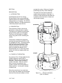
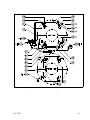
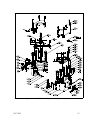
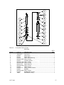
The elevator/spider units are shipped as
illustrated in Figure 2-1. A specified set of
slip segments and guide rings are shipped
installed.
NOTE
The slip set and guide rings must
correspond to casing diameter or damage
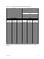
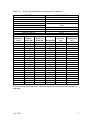
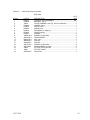
to slips and casing will result (see Table 31 or 3-2).
supporting the maximum limit of the
elevator, over the lifting lugs.
b. Close and secure link retainers.
NOTE
Be certain the elevator control handle is
on the side faces the stabbing board, so
that the derrick man will have access to it.
c. Lubricate as indicated on page 13
(Figure 4-1).
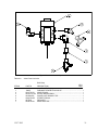
d. Connect air line (Paragraph 2-5).
2-2. INSTALLATION PREPARATION
Clean, dry air, filtered and regulated to 70
to 125 psi is required to operate these
units.
2-3. SPIDER INSTALLATION
NOTE
If an adapter plate is used, check to be
certain it is level, so the spider will be in
line with the bore hole. Install the adapter
plate with centering lugs facing up. These
stops help to keep the spider centered. If
an adapter plate is not used, check with
rotary table manufacturer to be certain it
will support spider unit.
a. Hoist spider into position over bore
hole.
b. Lubricate as indicated on Page 13
(Figure 4-1).
c. Connect air lines (Paragraph 2-5).
2-4. ELEVATOR INSTALLATION
NOTE
Be certain links and rig hook are capable
of supporting the load indicated on the
body of the unit (350 or 500 Tons).
a. Open elevator link retainers and slide
the bottom eyes of the links capable of
12/17/2013
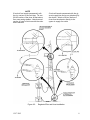
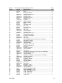
Figure 2-1.
Elevator and Spider Installed
6