1
GE Fanuc Automation
CIMPLICITY® Monitoring and Control Products
CIMPLICITY HMI Plant Edition
Tracker
Routing Control Objects Operation Manual
GFK-1408C
July 2001
GFL-005
Following is a list of documentation icons:
Warning notices are used in this publication to emphasize that hazardous voltages, currents,
temperatures, or other conditions that could cause personal injury exist in the equipment or
may be associated with its use.
In situations where inattention could cause either personal injury or damage to equipment, a
Warning notice is used.
Caution provides information when careful attention must be taken in order to avoid
damaging results.
Important flags important information.
To do calls attention to a procedure.
Note calls attention to information that is especially significant to understanding and
operating the equipment.
Tip provides a suggestion.
Guide provides additional directions for selected topics.
This document is based on information available at the time of publication. While efforts have been made to be accurate,
the information contained herein does not purport to cover all details or variations in hardware or software, nor to
provide for every possible contingency in connection with installation, operation, or maintenance. Features may be
described herein which are not present in all hardware and software systems. GE Fanuc Automation assumes no
obligation of notice to holders of this document with respect to changes subsequently made.
GE Fanuc Automation makes no representation of warranty, expressed, implied, or statutory with respect to, and
assumes no responsibility for the accuracy, completeness, sufficiency, or usefulness of the information contained herein.
No warranties of merchantability or fitness for purpose shall apply.
CIMPLICITY is a registered trademark of GE Fanuc Automation North America, Inc.
Windows NT and Windows 2000 are registered trademarks of Microsoft Corporation
This manual was produced using Doc-To-Help®, by WexTech Systems, Inc.
Copyright 2000-2001 GE Fanuc Automation North America, Inc.
ii
CIMPLICITY HMI Routing Control Objects Operation Manual–July 2001
GFK-1408C
Preface
Contents of this Manual
Chapter 1. Introducing Routing Control Objects: Introduces CIMPLICITY HMI
Routing Control Objects.
Chapter 2. Learning about RCO: Provides an overview of the Routing Control
Objects module and interface requirements.
Chapter 3: Configuring Routing Control Objects: Discusses the RCO
Configuration Wizard and Provides instruction on configuring RCOs.
Chapter 4. Using the RCO Runtime User Interface: Discusses the options
available in the Routing Control Objects user interface.
Chapter 5. RCO Logging Configuration: Documents the configuration for ODBC
data logging of RCO information.
Chapter 6. Function Blocks Overview: Introduces the function blocks used by
RCO.
Chapter 7. Routing Function Blocks: Documents the routing function blocks for
RCO.
Chapter 8. Core Function Blocks: Documents core function blocks for RCO.
Chapter 9. Output Function Blocks: Documents the output function blocks for
RCO.
Chapter 10. Conditional Function Blocks: Documents the conditional function
blocks for RCO.
Chapter 11. Diagnostic Blocks: Documents the diagnostic blocks for RCO.
Chapter 12. PRT Function Blocks: Documents the Production Tracking function
blocks for RCO.
Chapter 13. Include Function Blocks: Documents the include function blocks for
RCO.
Appendix A. RCO External Decision: Documents the RCOExtDec Application
Programmer Interface (API) .
GFK-1408C
iii
Related Publications
For more information, refer to these publications:
CIMPLICITY HMI User's Manual (GFK-1180)
iv
Preface <number>
Contents
Introducing Routing Control Objects
1-1
About Routing Control Objects.............................................................................................. 1-1
Upgrade RCO Projects........................................................................................................... 1-2
Learning about RCO
2-1
About the Routing Control Objects Module .......................................................................... 2-1
RCO Overview....................................................................................................................... 2-6
RCO Execution Sequence........................................................................................ 2-7
Advanced RCO Concepts....................................................................................................... 2-8
RCODB_RP Process............................................................................................................ 2-10
Glossary for RCO Manual.................................................................................................... 2-11
Configuring Routing Control Objects
3-1
About the Tracker Configuration User Interface.................................................................... 3-1
Using the Execution Sequence to Your Advantage ................................................. 3-2
Open the Tracker Configuration User Interface..................................................................... 3-3
Tracker Configuration User Interface Overview.................................................................... 3-5
How to Create Routing Control Objects ................................................................................ 3-7
RCO Configuration Tasks...................................................................................................... 3-8
Step 1. Configure a Routing Control Site ................................................................ 3-9
Step 2. Configuring Triggers ................................................................................. 3-25
Step 3. Configuring Decisions ............................................................................... 3-28
Step 4. Configuring Routing Logic........................................................................ 3-32
Locking Operation ............................................................................................................... 3-35
Save RCO Configuration Data............................................................................................. 3-36
Additional Functions and Utilities ....................................................................................... 3-37
RCO Folder Properties........................................................................................... 3-37
Attribute Maintenance ........................................................................................... 3-39
Region Maintenance .............................................................................................. 3-40
Verify Utility.......................................................................................................... 3-43
Error List Utility .................................................................................................... 3-43
Alarming and Logging........................................................................................... 3-44
Using the RCO Runtime User Interface
4-1
About the RCO Runtime User Interface ................................................................................ 4-1
Connect the RCO Runtime User Interface ............................................................................. 4-2
Option 1. Connect to Local Project.......................................................................... 4-2
Option 2. Connect to Projects in an Existing RCO Profile ...................................... 4-4
Option 3. Connect to Projects from the Command Line.......................................... 4-5
Option 4. Connect to the Configuration Dialog ....................................................... 4-7
Select the Control Site............................................................................................................ 4-9
RCO_UI Window................................................................................................................. 4-10
Open Profile ......................................................................................................................... 4-14
GFK-1408C
Contents-v
Configure a Profile............................................................................................................... 4-15
Manually Create an RCO Profile ......................................................................................... 4-18
Additional Functions for an RCO Site ................................................................................. 4-20
Changing the Status of a Control Site .................................................................... 4-21
Managing Decisions............................................................................................... 4-23
Managing Triggers................................................................................................. 4-26
Searching for Control Sites.................................................................................... 4-30
Setting Alarming and Logging Options ................................................................. 4-31
RCO Logging Configuration
5-1
Overview................................................................................................................................ 5-1
Database Logger Tables for RCO .......................................................................................... 5-1
Database Logger Table Fields for RCO................................................................... 5-1
RCO Logging Configuration Files ......................................................................................... 5-3
Datalog.idt ............................................................................................................... 5-3
Data_field.idt ........................................................................................................... 5-4
Function Blocks Overview
6-1
About RCO Function Blocks ................................................................................................. 6-1
Routing Function Blocks
7-1
Balance Load.......................................................................................................................... 7-1
Block by Attribute.................................................................................................................. 7-4
Check Item Hold Status ......................................................................................................... 7-6
Check Process Capability..................................................................................................... 7-10
Check Region Full................................................................................................................ 7-13
Check Region Ready............................................................................................................ 7-14
Consume a Trigger............................................................................................................... 7-17
Eliminate by Weight ............................................................................................................ 7-18
Eliminate Decision Based on Attribute Spacing .................................................................. 7-19
Eliminate Decision Based on Rule....................................................................................... 7-22
Eliminate Decisions Based on Region Status....................................................................... 7-27
Eliminate Decision by Attribute........................................................................................... 7-28
Eliminate Decision by Attribute Attribute ........................................................................... 7-28
Eliminate Decision by Attribute Point ................................................................................. 7-31
Eliminate Decision by Attribute Value ................................................................................ 7-33
Eliminate Decision by Increasing Weight Percentages........................................................ 7-35
Eliminate Decision by Point................................................................................................. 7-38
Eliminate Decision by Point Point ....................................................................................... 7-38
Eliminate Decision by Point Value ...................................................................................... 7-40
Eliminate Decision if not only Decision .............................................................................. 7-42
Eliminate Decision ............................................................................................................... 7-43
Eliminate Decisions with no Items in Source....................................................................... 7-44
Get Trigger Name ................................................................................................................ 7-46
Item Type Translation .......................................................................................................... 7-47
Look Back Blocking ............................................................................................................ 7-48
SelectDecisionByAttribute................................................................................................... 7-50
Select Decision by Attribute Point ....................................................................................... 7-50
Select Decision by Attribute Value ...................................................................................... 7-53
Select Decision by Point Value............................................................................................ 7-55
Select Decision with Highest Order & Weight .................................................................... 7-57
Select Decision..................................................................................................................... 7-58
Select Highest Order Decision ............................................................................................. 7-59
Select Lowest Order Decision.............................................................................................. 7-60
Contents-vi
CIMPLICITY HMI Routing Control Objects Operation Manual–July 2001
GFK-1408C
Select Most Empty Region................................................................................................... 7-61
Select Most Full Region....................................................................................................... 7-62
Select Next Highest Order Decision .................................................................................... 7-63
Select Oldest Item ................................................................................................................ 7-64
Core Function Blocks
8-1
Append a Decision in ExtDecBuffer...................................................................................... 8-1
Clear the Cached Items .......................................................................................................... 8-1
Consume a Trigger................................................................................................................. 8-2
Custom Block......................................................................................................................... 8-2
Delete at a Decision in ExtDecBuffer .................................................................................... 8-3
Delete a Decision in ExtDecBuffer ........................................................................................ 8-4
Exit Sub.................................................................................................................................. 8-4
Fill Array Point ...................................................................................................................... 8-5
Fill RCO Array Point ............................................................................................................. 8-5
Flush the ExtDecBuffer.......................................................................................................... 8-6
Get Decision Attribute ........................................................................................................... 8-6
Get Decision Status ................................................................................................................ 8-7
Get Ext Decision List ............................................................................................................. 8-7
Get Production Data............................................................................................................... 8-7
Increment Attribute ................................................................................................................ 8-8
Increment Point ...................................................................................................................... 8-8
Insert a Decision in ExtDecBuffer ......................................................................................... 8-9
Logstatus Generator ............................................................................................................... 8-9
Region Full Check................................................................................................................ 8-10
Request External Decisions.................................................................................................. 8-10
Reset a Trigger ..................................................................................................................... 8-11
Select next External Decision .............................................................................................. 8-11
Set Array Point..................................................................................................................... 8-12
Set Attribute ......................................................................................................................... 8-12
Set Attribute to Text and Integer.......................................................................................... 8-12
Set Attribute with Attribute.................................................................................................. 8-13
Set Attribute with Point........................................................................................................ 8-14
Set Attribute with RCO Variable ......................................................................................... 8-14
Set Attribute with Value....................................................................................................... 8-14
Set Auto-trigger Interval ...................................................................................................... 8-14
Set Decision Attribute .......................................................................................................... 8-15
Set Decision Status............................................................................................................... 8-16
Set Point with Attribute........................................................................................................ 8-17
Set Point with Point.............................................................................................................. 8-17
Set Point with Timestamp .................................................................................................... 8-18
Set Point with Value............................................................................................................. 8-18
Set RCO Variable with Attribute ......................................................................................... 8-19
Set RCO Variable with Expression ...................................................................................... 8-21
Set RCO Variable with Point ............................................................................................... 8-21
Set RCO Variable with a Special Value............................................................................... 8-22
Set RCO Variable with Timestamp...................................................................................... 8-22
Set RCO Variable with Translate Value .............................................................................. 8-23
Set RCO Variable with Value (Extended) ........................................................................... 8-24
Set RCO Variable with Value .............................................................................................. 8-24
Set Wait Encountered Flag................................................................................................... 8-25
GFK-1408C
Contents
Contents-vii
Output Blocks
9-1
Attribute Counts ..................................................................................................................... 9-1
Conditional Alarm with Attribute .......................................................................................... 9-3
Conditional Alarm with Point ................................................................................................ 9-3
Generate Alarm ...................................................................................................................... 9-4
Process Bits & Words ............................................................................................................ 9-5
Set Asynch Validation Value ................................................................................................. 9-6
Update Counts........................................................................................................................ 9-7
Update Spacing, Attribute and Total Released Counts ........................................................ 9-10
Conditional Function Blocks
10-1
Case Block ........................................................................................................................... 10-1
Case Else Block.................................................................................................................... 10-2
Check all Region's (related to Decisions) Status (Extended) ............................................... 10-2
Check all Region's (related to Decisions) Status.................................................................. 10-4
Check if any Source Region has Decision ........................................................................... 10-5
Compare Attribute................................................................................................................ 10-5
Compare Attribute with Attribute ........................................................................................ 10-6
Compare Attribute with Point .............................................................................................. 10-9
Compare Attribute with Value ........................................................................................... 10-11
Compare Point with Point .................................................................................................. 10-13
Compare Point with Value ................................................................................................. 10-15
Compare RCO Variables.................................................................................................... 10-17
Else Block .......................................................................................................................... 10-19
Else If ( Expression ).......................................................................................................... 10-19
End If ................................................................................................................................. 10-20
End Select Block ................................................................................................................ 10-20
End While .......................................................................................................................... 10-21
If (Expression).................................................................................................................... 10-21
Select Block ....................................................................................................................... 10-23
While (Expression)............................................................................................................. 10-25
Diagnostic Blocks
11-1
Dump Available Decisions................................................................................................... 11-1
Site Log Generator ............................................................................................................... 11-2
PRT Function Blocks
12-1
Add PRT Item ...................................................................................................................... 12-1
Associate Item...................................................................................................................... 12-2
Delete Item........................................................................................................................... 12-4
Disassociate Item ................................................................................................................. 12-4
Load PRT Item into Item Variable....................................................................................... 12-5
Load PRT Region Data into Region Variable...................................................................... 12-5
Move Item ............................................................................................................................ 12-6
Set PRT Item Data ............................................................................................................... 12-7
Set PRT Item with another PRT Item .................................................................................. 12-8
Set Source Region as Decision Made................................................................................. 12-10
Include Function Blocks
13-1
Include File .......................................................................................................................... 13-1
Contents-viii
CIMPLICITY HMI Routing Control Objects Operation Manual–July 2001
GFK-1408C
Appendix A - RCO External Decision
A-1
Overview............................................................................................................................... A-1
RCO External Decision API Functions................................................................................. A-2
ExtDec_api_init ...................................................................................................... A-2
ExtDec_api_get_msg .............................................................................................. A-3
ExtDec_api_init_comm .......................................................................................... A-4
ExtDec_api_send_decision ..................................................................................... A-4
ExtDec_api_term .................................................................................................... A-5
RCOExtDec API Calls in relation to PDC_API Calls ............................................ A-5
External Decision Simulator ................................................................................................. A-6
Set 1. Framework Functions (ExtDec_Sim............................................................. A-6
Set 2. Data Management and Event Handler Functions (ExtDec_SimData.cpp) ... A-7
Set 3. RCO External Decision API Calls ................................................................ A-9
Process Flowchart ................................................................................................... A-9
Simulator Configuration Requirements............................................................................... A-10
External Decision Buffer..................................................................................................... A-17
RcoDecisionBuffer ............................................................................................... A-17
RcoExtDecision .................................................................................................... A-21
Index
GFK-1408C
i
Contents
Contents-ix
Introducing Routing Control
Objects
About Routing Control Objects
The Routing Control Objects (RCO) Module is one of two modules that make up the
Tracker product option. This application module is fully integrated with CIMPLICITY
HMI software's base system functionality to enhance its already powerful monitoring
ability in a full range of computer-integrated manufacturing environments.
The Base System functionality—Point Management, Alarm Management, Database
Logging facilities, and a full-functioned User Interface—enables you to collect data for
reporting and to view data in lists, graphic status displays, and alarms. The RCO module
also has the ability to integrate with many of the industry-standard data communications
products.
The Routing Control Objects Module is a flexible factory floor tool that provides:
Records of production counts at workstations.
Graphic monitoring of automatic data point values.
Fault reporting through direct point values and alarms.
CIMPLICITY HMI's flexible system architecture and modular design allows you to easily
add-on options for enhanced functionality. The Routing Control Object module of the
Tracker option coordinates the flow of material within a production facility.
Note: This manual is not intended to provide instruction on CIMPLICITY HMI or your
Windows operating system, and it is assumed that users have a working knowledge of
both software products. Please refer to the documentation that originally came with your
software for questions about CIMPLICITY and Microsoft Windows.
GFK-1408B
1-1
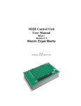
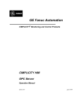
Upgrade RCO Projects
Whenever you install the latest upgrade to your CIMPLICITY software, it is a good idea
to upgrade your RCO projects. This will enable you to take advantage of the
enhancements offered in the Service Pack or CD release. For example, the RCODB_RP
process, which is the database server for RCO_UI clients, can only be started after you
upgrade your RCO projects.
To upgrade RCO project:
1.
Open your project in the CIMPLICITY Workbench.
2.
Double-click the Tracker Configuration icon
Configuration User Interface.
3.
Right-click a folder in the RCO directory.
4.
Select Lock in the popup menu (if not already checked).
to open the Tracker
A check mark appears next to Lock; the folder is locked.
5.
(If Activate is not checked when you checked Lock) right-click the folder again.
.
Select Activate.
A check mark appears next to Activate; the project is activated.
7.
Verify the project using one of the following methods.
Method 1–Toolbar button
Click
on the Tracker toolbar.
Method 2–Menu option
A. Click Tools on the Tracker menu bar.
B. Select Verify.
Method 3–Keyboard
Press Crtl+Y on the keyboard.
Result: The RCO project is updated and enhancements are available.
3A
3B
1
2
To upgrade RCO
1 Right-click folder.
2
2. Check Lock, Activate
3. Verify
A.
A Tools-Verify
B Verify button
B.
C. Ctrl+Y on keyboard
1-2
CIMPLICITY HMI Routing Control Objects Operation Manual
GFK-1408B
Learning about RCO
About the Routing Control Objects Module
The Routing Control Objects (RCO) module is one of two modules that make up the
CIMPLICITY Tracker software option. The other module is the Production Tracking
(PRT) module, which tracks parts / assemblies through the manufacturing process. This
module requires the configuration of a tracking model that is supported by a powerful
database which tracks a product from the inception of raw materials on the factory floor
to finished goods. The RCO module works in tandem with PRT, using its data to perform
enhanced production routing decisions at runtime.
Wherever a routing decision has to be made on the factory floor, an RCO will monitor
the site and make decisions based on current production conditions. Each routing site
monitored by an RCO is called a control site.
User Interfaces
There are two interfaces associated with the RCO module:
Tracker Configuration User Interface
Used for creating and configuring all of the
components related to a control site.
RCO Runtime User Interface
Used for monitoring runtime data of a control
site. Also used for manual intervention, e.g.
manual decision.
RCO Components
There are several components that are integral to the creation, configuration, and
implementation of a routing control object, each of which are explained in the following
sections:
Control Site
Triggers
Decisions
Function Blocks
Routing Logic Modules
See the Tracker Getting Started Guide, GFK-1694 for complete details about configuring
a Tracking Model.
GFK-1408C
2-1
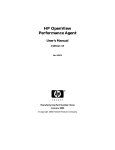
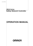
Control Site
A control site is a location in the factory where a production routing decision must be
made.
Region 2
Control site at a split route
Region 3
Region 1
Control site for split
route. A routing decision
must be made at this
juncture.
Region 4
Events at a control site have a domino-like effect as follows:
Simple Control Site Sequence
Site Triggered
2-2
Current
production
conditions
Logic Module
eliminates invalid
decisions
Decision
determined
CIMPLICITY HMI Routing Control Objects Operation Manual–July 2001
Output Module =
product routing
GFK-1408C
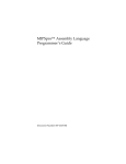
Triggers
A trigger initiates the cycle of events at a control site. A trigger is commonly one or more
configured points. When a group of points are configured to trigger a control site, they
must be triggered in the correct sequence to start the cycle of events.
Example
1. Points A, B and C must trigger in sequence to send refrigerator to next region.
RCO
Point A
Point B
Point C
g
2. Points A, B and C. trigger in sequence starting the cycle of events at the control site.
ON
ON
ON
g
RCO
Point A
2-3
Point B
Point C
CIMPLICITY HMI Routing Control Objects Operation Manual–July 2001
GFK-1408C
Decisions
A decision is made at a control site in the factory based on current production conditions.
RCO uses "decision-based logic" to execute production routing. This means that unlike
traditional software where the outcome is determined after conditions have been
evaluated decisions are determined in advance. Therefore, all possible outcomes are
known in advance and eliminated based on the configured routing logic for the current
production conditions.
After the Logic Module ends, RCO determines which decision to execute as follows:
Possible Remaining Decisions RCO Executes
One
That decision
None
None script
Multiple
Multiple script
The control cycle is ended when RCO detects that the decision is either successfully or
unsuccessfully completed.
Example
1. All possible decisions are known in advance
RCO
Decision 1
Send Blue Cars
to next region
Decision 2
Send Green Cars
to next region
Decision 3
Send Red Cars to
next region
RED
2. Configured function blocks eliminate decisions based on current production conditions
Function blocks
ELIMINATED
ELIMINATED
Decision 1
Send Blue Cars
to next region
Decision 2
Send Green Cars
to next region
EXECUTE
Decision 3
Send Red Cars to
next region
RED
Red car is sent down the line to the next region.
2-4
CIMPLICITY HMI Routing Control Objects Operation Manual–July 2001
GFK-1408C
Function Blocks
Function blocks are standard logic routines from which you create logic modules for
routing product, generating errors, disabling the control site, and so on. You set the
parameters on each function block so that it meets your specific needs in the production
environment. Further, two or more function blocks can be grouped together to meet your
production criteria.
There are an abundant number of function block templates to choose from in various
categories as follows:
Function block
Description
Conditional
Evaluates 'If-Then-Else' conditions
Core
Performs all-purpose function
Diagnostic
Assists in resolving RCO issues
Include
Enables the inclusion of a file into the generated script.
Output
Produces an output in the system, for example generating an alarm
PRT
Performs PRT functions
Routing
Performs routing functions
Routing Logic Modules
A Routing Logic Module (RLM) is one or more function blocks configured to achieve a
particular routing result. When using the function blocks provided with the Tracker
software option, you set the parameters using dialogs in the Tracker Configuration User
Interface. There is no need to write code to achieve routing results, the function blocks
automate the entire process for you making this a highly effective feature of the RCO
subsystem.
Example
1. Site is triggered and an RLM is run with a single function block.
RCO
Yellow
Eliminate Decision by Point Value
Function block parameters:
Decision: Region 1 to Region 2
Point ID - Pnt_1_Val
Value - Green
Comparison Operator - Equal to
Comparison Type - Alphanumeric
2. RLM is matched against the point value and decision is executed.
Point Value
Pnt_1_Val = Yellow
RLM
Value = Green
Values do not
match, decision is
not elimiated
EXECUTE
Decision
Send printer to
Region 2
Yellow
Printer is sent to Region 2
2-5
CIMPLICITY HMI Routing Control Objects Operation Manual–July 2001
GFK-1408C
RCO Overview
RCO is an independent process that monitors control sites on the factory floor. Like a
traffic cop directing traffic, RCO directs the flow of product through the manufacturing
environment using 'decision-based logic'. The following diagram is a simple rendition of
a control site monitored by an RCO on the factory floor:
Example of a Control Site monitored by RCO
Decision 1
Send dryer to Region 2
Decision 2
Send dryer to Region 3
Current Production Conditions:
Regions 2 & 3 are IN USE.
Decision 3
Send dryer to Region 4
Region 2 - Heating Unit Installation
IN USE
2. Routing Logic
Modules run and
eliminate decisions based
on current production
conditions.
Control Site
g
Region 3 - Temperature Gauge Installation
Region 1
IN USE
1. Site is triggered
3. Output Module runs and
by Operator.
sets point values sending the
dryer to Region 4.
Region 4 - Motor Installation
Reset
control site
4. Control cycle ends
and resets control site to
wait for next trigger.
2-6
CIMPLICITY HMI Routing Control Objects Operation Manual–July 2001
GFK-1408C
RCO Execution Sequence
The logic used by RCO to execute decisions is illustrated in the flowchart below.
RCO Execution Sequence
Site Triggered
Logic Module
All decisions
eliminated or
Wait flag is set
Yes
None Module
No
2+ decisions still
or error flag is set
Yes
Multiple Module
No
Wait for Ready
Point=Ready Val
Sync Validation
(Site)
5 second timeout or
file abort state set
Yes
Site Output
Module
Set Done Point
Decision Output
Module
Decision Marked
Sync Validation
(Decision)
Inprocess or
Completed
Yes
End Execution
Cycle
2-7
CIMPLICITY HMI Routing Control Objects Operation Manual–July 2001
GFK-1408C
Advanced RCO Concepts
In order to configure the control sites in your facility so that they operate based on your
criteria for production flow and existing production conditions, it is important to learn
about the advance RCO concepts.
This section describes:
Synchronous validation
Asynchronous validation
Control site: Synchronous validation
Synchronous validation occurs during the control cycle to verify that a carrier has
arrived at the stop position and allows the control site to stay in synchronization with the
factory floor.
Configuration Guidelines
In the Tracker Config UI, the following fields are configured to enable synchronous
validation:
Dialog
Control Site
Group Name
Execution Sequence
Field Name
Verification Point
Verification Value
Value
Point ID
Boolean, integer or string
See "Configuring Routing Control Objects" chapter in this manual for details about
configuring points and point values for an RCO.
Example of a Synchronous Validation
Region 2
RCO Site
2
B
Region 1
1
A control cycle is in progress
moving Monitor A to Region 4.
2
Monitor B has moved into the Split
control site.
3
RCO waits for synchronous validation
before allowing the control site to trigger.
Region 3
1
A
Control
cycle ends
3
2-8
Set
Validation
Point
CIMPLICITY HMI Routing Control Objects Operation Manual–July 2001
Region 4
GFK-1408C
Control site: Asynchronous validation
Asynchronous Validation enables RCO to wait on one or more Validation points while
continuing to execute additional control cycles. This means that when a control cycle is
in progress, the control site can be triggered (to start a new control cycle) while waiting
for the Verification point to set and to mark the decision 'Complete'.
Decisions
Each decision has two additional fields: Validation Point and Default Validation Value.
The Validation Point must be set to the Validation Value in order for the decision to be
considered complete. With Asynchronous Validation, RCO will continue to execute
control cycles while waiting for validation to occur.
When the logic module has selected a decision, the output modules will run and the
decision will appear in the RCO_UI as 'Pending'. If the decision has a Validation Point
configured, the site will wait for the Validation, and process any additional triggers. The
decision waiting for validation will be marked as 'InProcess' until the Verification.
RCO maintains a history of the last 32 decisions. When a new decision is made, it is
added to the decision history. When the maximum number of configured decisions is
exceeded, the oldest decision is removed from the list. RCO alarms if a decision is
removed and was not validated.
Once a decision has been removed from the list, it is considered canceled.
Decision Complete
When Async Validation is configured for a decision, and the default value is specified in
the Decisions dialog box or in the Output Module via the Set Asynch Validation Value
function block, the decision status reads, 'InProcess'. When RCO receives a Point update
whose value is equal to the configured Validation Point, the decision is then marked
'Completed'.
Configuration Guidelines: When configuring Decisions for an RCO, set the
Validation Point and designate a value in the Val. Point Value field. If these fields are not
configured, the decision will not wait for a validation Point to be updated, and the
decision will be marked as complete at the end of the cycle. See topics, "How to
Configure Decisions," and "How to Create a Routing Control Object—Output Modules
Group" for instructions.
Use the Set Async Validation Value function block to change the default value for a
particular cycle. You can assign the value or tie it to a variable. Configure this function
block in the output module only. Note that if the default value is not configured in the
Decisions dialog box, but is configured in the output module using the above-mentioned
function block, the decision will wait for the validation Point to be updated with the value
assigned in the function block for completion.
The site must have a thread available for performing async validation. Set the thread
count accordingly in its folder's properties. See "RCO Folder Properties" for details.
2-9
CIMPLICITY HMI Routing Control Objects Operation Manual–July 2001
GFK-1408C
RCODB_RP Process
The RCODB_RP Process supplies the details of the RCO sites configured in a project to
any requesting RCO Runtime UI process. The RCO configuration data is stored in a SQL
server database to which this process will have an open connection in order to retrieve
information and deliver to the requesting process.
2-10
CIMPLICITY HMI Routing Control Objects Operation Manual–July 2001
GFK-1408C
Glossary for RCO Manual
Take a moment to become familiar with the terms listed below as they will be used
throughout this manual.
Asynchronous Validation
Asynchronous Validation enables RCO to wait on one or more Validation points while
continuing to execute additional control cycles. This means that when a control cycle is
in progress, the control site can be triggered (to start a new control cycle) while waiting
for the Verification point to set and to mark the decision 'Complete'.
Decisions
A decision is an action you configure to be performed by an RCO at a control site.
Decisions typically represent a transition from one tracking region to another but may
also represent other actions such as tracking updates, set Points, or alarms. Decisions are
defined for an RCO under the Decisions branch of the RCO configuration tree.
Folders
Folders are used in the RCO Configuration directory to organize control sites and they
represent the "process" that runs under Windows NT. Each folder is responsible for
executing the control sites it contains. Although folders may appear within folders, a
folder will not execute any folders it contains. Folders under folders are a separate
process. Under the Windows NT Task Manager, folders appear as a process called
"RCOSite" Under CIMPLICITY HMI program control, they show up with the name of
the actual folder.
Function Blocks
Function blocks are standard logic routines provided with the Tracker product that may
be configured in logic modules to perform decision-making logic.
Merge Route
Many routes to one route.
Output Logic
Output Logic performs the output actions required based on the current decision and
current factory conditions. Output Logic may contain one or more function blocks or a
custom Basic Control Engine (BCE) program.
Route
A link between two regions in the manufacturing process.
Routing Control Objects (RCO)
Routing Control Objects (RCOs) may be configured to perform routing control, process
setup, and tracking updates based on current factory conditions. RCOs can be configured
for any number of locations in the production process.
2-11
CIMPLICITY HMI Routing Control Objects Operation Manual–July 2001
GFK-1408C
Routing Logic
Routing Logic determines the best decision to make from all configured decisions based
on current factory conditions. Routing Logic is arranged and managed in components
called Routing Logic Modules. Routing Logic is defined for an RCO under the Routing
Logic branch of the RCO configuration tree.
Routing Logic Module (RLM)
A Routing Logic Module is logic configured to achieve a particular routing result such as
color blocking or load balancing across several lines. An RLM may consist of one or
more function blocks or a custom Basic Control Engine (BCE) program.
Simple Route
Part/assembly follows one route.
Splerge Route
Many routes to many routes.
Split Route
One route to many routes.
Synchronous Validation
Synchronous validation requires the control cycle in progress to complete before the site
can be triggered and a new cycle initiated. Two or more control cycles cannot run
simultaneously at a control site with synchronous validation.
Tracker Configuration User Interface
The Tracker Configuration User Interface enables you to configure RCOs for specific
control sites through a graphical user interface. A new RCO will automatically generate a
Triggers, Decisions and Routing Logic applet, which are represented in a tree directory
similar to Windows Explorer directory and file structure. When you click on an applet in
the directory, a corresponding dialog for configuring and viewing RCO data is displayed
in the left pane of the window.
Triggers
A trigger initiates an RCO control cycle. A trigger may be configured as one Point that
on update initiates the control cycle or several Points that on update (in the correct
sequence) initiate the control cycle. Several triggers may be configured at a Tracker
Control Site. Triggers are defined for an RCO under the Triggers branch of the RCO
configuration tree.
2-12
CIMPLICITY HMI Routing Control Objects Operation Manual–July 2001
GFK-1408C
Configuring Routing Control
Objects
About the Tracker Configuration User Interface
The Tracker module provides you with two subsystems for configuring and monitoring
control sites. Both can be accessed from your project's Workbench. They are described as
follows:
Icon
Subsystem
Tracker Configuration
User Interface
RCO Runtime User
Interface
Objective
Graphical user interface for
configuring RCOs and all
associated components.
Graphical user interface for
monitoring runtime data on
control sites.
The Tracker Configuration User Interface (TrackerConfig_UI) provides you with an
integrated structure for configuring all of the components needed at the control site level
for automated production flow.
GFK-1408C
3-1
Using the Execution Sequence to Your Advantage
Here is another look at the execution sequence at a control site. It is a good idea to keep
this is mind when configuring RCO. In order to take advantage of its powerful
monitoring abilities, there are several components that must be configured from triggers
to decisions to output modules, and so on.
RCO Execution Sequence
Site Triggered
Logic Module
All decisions
eliminated or
Wait flag is set
Yes
None Module
No
2+ decisions still
or error flag is set
Yes
Multiple Module
No
Wait for Ready
Point=Ready Val
Sync Validation
(Site)
5 second timeout or
file abort state set
Yes
Site Output
Module
Set Done Point
Decision Output
Module
Decision Marked
Sync Validation
(Decision)
Inprocess or
Completed
Yes
End Execution
Cycle
3-2
CIMPLICITY HMI Routing Control Objects Operation Manual–July 2001
GFK-1408C
Open the Tracker Configuration User Interface
Use the Tracker Configuration User Inteface to configure a routing control object. The
Tracker Configuration Interface is launched from the CIMPLICITY Workbench.
To open the Tracker configuration user interface:
1.
Click Start on the Windows task bar.
2.
Select Programs>CIMPLICITY>HMI>
Workbench.
3.
Click
to open the
on the Workbench toolbar.
The Open dialog box opens.
4.
Navigate to your project.
5.
Double-click the project.
6.
Click OK.
The project opens in the Workbench.
6.
Double-click the Tracker Configuration icon
directory.
in the Workbench
Result: The Options dialog box will display when launching the user interface for
the first time; otherwise, the Tracker Configuration User Interface will display. Go
to next page for instructions on entering data source information.
Tip: Open your project quickly by clicking on it in the recently used list that displays
near the bottom of the File menu. The last four projects accessed will display in the list.
3-3
CIMPLICITY HMI Routing Control Objects Operation Manual–July 2001
GFK-1408C
Data Source Information
Associated configuration data is stored in a SQL Server database. Specify the data source
to be used with the RCO database as instructed below.
/
To enter data source information:
1.
Click Tools on the Tracker window menu bar.
2.
Select Options.
The Options dialog box opens.
3.
Select the data source from the drop-down list in the Datasource field.
This must be defined as a system data source.
4.
Enter the ID that allows access to the SQL Server data source in the Login ID
field.
5.
Enter the corresponding password for the Login ID in the Password field.
6.
Check the Drag and Drop box to allow sites, triggers and decisions to be
dragged and dropped between folders.
7.
Click OK.
Result: The data source is designated. All required tables are created in the
database as specified by the designated data source.
Data Source Options
Fields are
disabled.
Enables drag and
drop functionality
between RCO folders.
Launches the
ODBC Database
Administrator
dialog box.
Note: Click ODBC Admin to run the standard ODBC 32-bit administrator tool for
ODBC configuration. Any change to the designated data source must be changed through
the Tracker Configuration User Interface.
3-4
CIMPLICITY HMI Routing Control Objects Operation Manual–July 2001
GFK-1408C
Tracker Configuration User Interface Overview
The Tracker Configuration User Interface opens after the data source has been initially
designated, and when subsequently launching the interface from the Workbench. All of
the tools necessary to configure control sites and associated components are provided in
the window.
The menu bar provides you with several options for configuring and viewing RCO
information. Also, the toolbar buttons allow you to perform some of the most common
functions with one click. The integrated structure holds the RCO directory of files in the
left pane, and the related configuration dialogs in the right pane.
Tracker Configuration User Interface
Menu and tool bar
provide options for
configuring RCOs.
Directory structure for
organizing and viewing
RCO components.
Directory structure for
organizing and viewing
PRT components.
Work area for
configuring RCO
components
3-5
CIMPLICITY HMI Routing Control Objects Operation Manual–July 2001
GFK-1408C
RCO Directory Structure
The RCO directory is organized in a hierarchy so that information for a control site can
be easily accessed, viewed, and modified.
CIMPLICITY Routing Control Object Configuration window
Main folder
Site folder
RCO
Trigger folder
Triggers
Decision folder
Decisions
Routing Logic folder
Routing Logic modules
Each level of data in the RCO hierarchy has a function as follows:
Icon
Type
RCO Site
Locked RCO Site
Trigger folder
Trigger
Decisions folder
Decision
Routing_Logic folder
Routing logic
modules
3-6
Objective
Contains all of the instructions for making
production routing decisions at the control site.
RCO site icon changes when it is locked. Locking
the site enables modification of its properties.
Folder that holds all of the configured triggers for the
control site.
One or more points that will activate the control site
when its defined conditions are met.
Folder that holds all of the configured decisions for
the control site.
Instructions for executing an output module, which
in turn, sets a series of points. Actual production
routing is performed at this juncture.
Folder that holds all of the configured routing logic
modules for the control site.
Modules that consist of function blocks to achieve a
particular routing result in line with factory
conditions.
CIMPLICITY HMI Routing Control Objects Operation Manual–July 2001
GFK-1408C
How to Create Routing Control Objects
You can create and configure new routing control objects in the Tracker Configuration
User Interface. Begin by placing a blank RCO in the directory.
To create a new routing control object:
1.
Select the main project folder in the left pane of the window.
2.
Click File on the menu bar.
3.
Select New>Routing Control Object.
Result: A New_Site will display in the directory and the right pane will display a
dialog for configuring the control site. Click on the + to expand the directory to
view three folders automatically created by the configuration user interface:
Triggers, Decisions and Routing Logic.
Tip: Create Folders to
organize your RCO Sites.
1. Click File.
2. Select New.
3. Select Routing
Control Object.
A New Site is created in
the directory.
3 subfolders are
automatically created.
Right pane displays dialog
to configure RCO.
Tip: Organize information in the directory by creating folders. From the File menu,
select New>Folder and a folder icon will display in your directory. You can then drag
and drop sites into and between folders.
3-7
CIMPLICITY HMI Routing Control Objects Operation Manual–July 2001
GFK-1408C
RCO Configuration Tasks
In order to configure an RCO you must first configure the site, and then all of its related
components. Detailed instructions, guidelines and examples are provided for each of the
associated steps and tasks.
Steps to configure an RCO include:
3-8
Step 1.
Configure a Routing Control Site
Step 2.
Configure Triggers
Step 3.
Configure Decisions
Step 4.
Configure Routing Logic
CIMPLICITY HMI Routing Control Objects Operation Manual–July 2001
GFK-1408C
Step 1. Configure a Routing Control Site
Once you have created a new site in the Tracker Configuration User Interface, configure
the control site using the integrated dialogs in the right pane of the window.
Configuration at the RCO site level consists of points and logic modules that are common
for all items and events.
Important: Configuration of lower-level data items, for example triggers or decisions,
will override site level configuration.
Control Site Configuration
Points
Decisions
Output Modules
1. Control site configuration
is common for all items and
events.
Control Site Configuration
Points
Decisions
Output Modules
2. Configuration of lowerlevel data items overrides
control site configurtion.
To configure a control site, perform the following tasks:
A. Lock site
B. Name and describe RCO
C. Configure the General Setup group
D. Configure the Output Modules group
E. Configure the Execution Sequence group
F.
3-9
Configure the Automatic Triggers group
CIMPLICITY HMI Routing Control Objects Operation Manual–July 2001
GFK-1408C
Task A. Lock site
In order to configure an RCO, the site must be locked. When the site is locked, all of the
fields in the associated dialog are eligible for modification.
To lock an RCO site:
1.
Select the site in the RCO directory and right-click.
2.
Select Lock from the popup menu.
Result: Using either method, the Lock option on the popup menu is checked
indicating it is the active option. All of the fields in the dialog (left pane) are active.
3-10
CIMPLICITY HMI Routing Control Objects Operation Manual–July 2001
GFK-1408C
Task B. Name and describe RCO
In the top group of the RCO dialog, provide a unique name and description for the RCO.
The resource is also designated here.
To name and describe RCO:
1.
Enter a unique name for the RCO in the Name field.
2.
Enter a brief description for the purpose of the RCO in the Description field.
3.
Enter a Resource ID.
Click either:
to browse for an existing resource in the project, or
to designate a new resource.
RCO dialog - top group
Browse
Popup
4.
Check the Enable Unexpected point processing box to allow RCO to
generate an alarm when a point change comes into a site that is unexpected.
Guidelines
Unexpected point processing applies to three RCO point types: Trigger,
Validation and Verification. The Enabled Unexpected point processing
option allows the RCO system to disable the control site when a point change
occurs on one of these point types that is "not expected." An error will also
display in the RCO_UI, and an alarm will be generated. Configure alarm state
using the Alarming/Logging dialog box—see page 44 for details.
3-11
CIMPLICITY HMI Routing Control Objects Operation Manual–July 2001
GFK-1408C
Example
Example of Unexpected point processing
Trigger Sequence A
Waiting for
point
Waiting for
point
TRIG_POINT_1
TRIG_POINT_2
TRIG_POINT_3
Point Received by RCO
3-12
Trigger Sequence B
Unexpected
Point
TRIG_POINT_3
TRIG_POINT_2
TRIG_POINT_1
Comments
TRIG_POINT_1
No
Trigger Sequence A expecting
point.
TRIG_POINT_3
No
Trigger Sequence B expecting
point.
TRIG_POINT_2
Yes
Site disabled
Error generated in RCO_UI
Alarm generated
Trigger,
Validation and
Verification.
CIMPLICITY HMI Routing Control Objects Operation Manual–July 2001
GFK-1408C
Task C. Configure the General Setup group
To configure the General Setup group:
1.
In the RLM Point field, browse for or create a new point that will be updated
during RCO runtime with the name of the RLM to be executed for the site.
Guidelines
The RLM point is a virtual point with a string data type. It is either updated at
Runtime with the name of the routing logic module to be executed, or a user can
set the point with the name of the RLM. Ensure that Enable Point is checked
on the General page of the Point Properties dialog box.
2.
In the Status Point field, browse for or create a point that is updated to indicate
the status of the control site.
Status point values are:
0
Enabled control site.
1
Disable control site.
3
Suspended control site.
Guidelines
The Status point is a virtual point with an integer data type. It is either updated
at Runtime with the value of the control site status, or a user can set the point to
manage the status of the control site. Ensure that Enable Point is checked on
the General page of the Point Properties dialog box.
RCO Configuration dialog - General Setup group
Popup
Browse
3.
In the Danger Point field, browse for or create a point that will determine if any
decisions without a 'local danger point' are to be rolled back.
Boolean values are:
0
No danger and decision is to be eliminated.
1
In danger and decision is to be rolled back.
Guidelines
The Danger point can be a device or a virtual point with a Boolean data type. It
is updated at runtime with the danger status of the control site. If a control site
has eliminated all decisions and has an always evaluate flag of 'Breakable with
Danger Point High', then the RCO system automatically checks the danger
point. When the Danger point = 1, then the RCO is in a danger state and the
system will automatically roll the list back to the previous logic block—see
figure for details. Ensure that Enable Point is checked on the General page of
the Point Properties dialog box.
3-13
CIMPLICITY HMI Routing Control Objects Operation Manual–July 2001
GFK-1408C
Example
1. Two of three function blocks are run eliminating all decisions.
RUN
RUN
Function
blocks
Function Block 1
Eliminate Blue
and green cars
Function Block 2
Eliminate Red
cars
ELIMINATED
ELIMINATED
Decisions
Decision 1
Send Blue Cars
Decision 2
Send Green Cars
Function Block 3
Eliminate Yellow
cars
ELIMINATED
Decision 3
Send Red cars
RCO
RED
2. Function block 2 has an always evaluate flag of 'Breakable' with Danger Point High.
RCO
Danger State
High
RCO_DNG_PT=1
3. RCO rolls back to previous decision and applies function block 3.
SKIP
SKIP
Function
blocks
Function Block 1
Eliminate Blue
and green cars
Function Block 2
Eliminate Red
cars
ELIMINATED
ELIMINATED
Decisions
Decision 1
Send Blue Cars
Decision 2
Send Green Cars
RUN
Function Block 3
Eliminate Yellow
cars
EXECUTE
Decision 3
Send Red cars
RCO
RED
Red car is sent down the line to the next region.
3-14
CIMPLICITY HMI Routing Control Objects Operation Manual–July 2001
GFK-1408C
Task D. Configure the Output Modules group
You can configure Output Modules at the site level to execute one or more function
blocks, or to execute a custom BCE script based on what happens when the routing logic
module is run. The Output Modules group consists of four fields, which are explained
below with detailed configuration options in the following sections.
For additional information about configuring output modules, refer to these sections:
Create a New Output Module
Use Predefined Output Module
Popup Menu Functions
Basic Control Engine (BCE) Scripts
To configure the Output Modules group:
1.
In the Single field, browse for or create an output module that will be executed
when a single (one) decision survives the routing logic, i.e. control site works
properly.
Guidelines
The Single Output module is run when one decision is left after the routing logic
module is run, and after the decision output logic is executed. This module is
most commonly used to run output logic that is common for all successfully
executed decision.
2.
In the Multiple field, browse for or create an output module that will be
executed when multiple (two or more) decisions survive the routing logic.
Guidelines
The Multiple Output module is run when two or more decisions are left after the
routing logic module is run. This module is used to fix the problem of having
multiple decisions left and can be used to generate an alarm for user
intervention. Using the RCO Execution Sequence as a guide, note that the
control site cycle ends after the Multiple Output module is run.
RCO Configuration dialog - Output Modules group
Popup
Browse
3.
3-15
In the None field, browse for or create an output module that will be executed
when there are no (zero) decisions that survive the routing logic.
CIMPLICITY HMI Routing Control Objects Operation Manual–July 2001
GFK-1408C
Guidelines
The None Output module is run when there are no decisions left after the routing
logic module is run. This module can be used to generate an alarm for user
intervention., or to set a done point that will in turn prepare the site to re-trigger
the control site. Using the RCO Execution Sequence as a guide, note that the
control site cycle ends after the None Output module is run.
4.
In the Runtime Error field, browse for or create an output module that will be
executed when routing logic fails during the decision-making cycle.
Guidelines
The Runtime Error output module is run when the routing logic fails during
execution. This module can be used to generate an alarm to initiate user
intervention, or to set a done point that will in turn prepare the site to re-trigger
the control site.
3-16
CIMPLICITY HMI Routing Control Objects Operation Manual–July 2001
GFK-1408C
Create a New Output Module
In the Output Modules group you have the option of creating a new output module, using
an existing output module, or editing an existing output module. An output module can
consist of one or more function blocks that work together to perform
To create a new output module:
adjacent to the field where you want to create a new output module.
1.
Click
2.
Select New from the popup menu.
The Output Logic Wizard opens.
Toolbar functions.
New
Delete
Move Down
Move Up
3.
Enter a unique Name to identify the output module.
4.
Enter a brief Description for the module.
5.
Click New
.
The Select a Function Block dialog box opens.
Module selection example
Expand folder.
Select module.
3-17
CIMPLICITY HMI Routing Control Objects Operation Manual–July 2001
GFK-1408C
6.
7.
Expand the Function Block Class folder to display the corresponding function
blocks. Descriptions are as follows:
Class
Description
Core
Generic, all-purpose blocks.
Conditional
Evaluates If-Then-Else conditions.
Routing
Performs routing functions.
Output
Produces an output in the system, such as generating an alarm.
Diagnostics
Performs diagnostic functions.
PRT
Performs PRT functions.
Include
Enables the inclusions of basic scripts.
Double-click the function block that is to be added to the output module.
The dialog box for the function block opens.
Example of a function block dialog box
Double-click on tags to configure value.
8.
Enter a brief Description for the module.
9.
Set parameters by double clicking on each of the Tags in the list box.
Note: The dialog box that opens is dependent upon the tag.
10. Set the value for the parameter using the provided input option, e.g. drop-down
list or popup menu.
Note: The input options in the Parameter dialog box vary by parameter. There
can be drop-down lists, popup menus, browse buttons or edit controls that can
be used to set the value of the parameter. In the example above, there is a dropdown list.
13. Click OK to return to the Select a Function Block dialog box.
14. Repeat procedure from step 7 to add other function blocks to the list; otherwise,
proceed to step 15.
15. Click OK to return to the Output Logic Wizard.
16. Click Compile to compile the output module and to display any syntactic errors
that may exist.
3-18
CIMPLICITY HMI Routing Control Objects Operation Manual–July 2001
GFK-1408C
17. Click OK to save the configuration of the output module and close the Wizard.
Check box enables /
disables function block.
Click to generate
output module.
Tip: Use the toolbar in the Wizard to add or delete function blocks, and to change the
position of the function block up or down in the list. Also, you can use the checkbox next
to each function block to enable or disable it in the list. Be sure to compile when you
have made changes to the function block list.
3-19
CIMPLICITY HMI Routing Control Objects Operation Manual–July 2001
GFK-1408C
Use Predefined Output Module
To use a predefined output module:
Once you have created one or more output modules, you can select one from the list and
use it as is, or you can edit it to comply with your requirements.
1.
Click
adjacent to the field where you want to add a predefined output
module.
The Module Browser window will display.
Double-click the
output module
—OR—
Select an output
module from the
list, and then...
...click OK.
2.
3-20
Do one of the following:
Double-click an output module in the list or
Select an output module from the available list and click OK.
CIMPLICITY HMI Routing Control Objects Operation Manual–July 2001
GFK-1408C
Popup Menu Functions
You can use the popup menu to perform additional operations.
Click
next to the output module field to display the popup menu.
a.
b.
c.
d.
e.
Edit...
a. Launches the Output Module Wizard to
enable creation of a new output module.
b. Allows editing of the function block in a
selected output module.
c. Launches the Module Browser for selecting a
predefined output module.
d. Deletes selected item.
e. Enables creation of BCE scripts.
Basic Control Engine (BCE) Scripts
When configuring output modules, you have the option of creating custom BCE scripts
for execution, rather than choosing a predefined function block.
See the CIMPLICITY Basic Control Engine Operation Manual (GFK-1180 ) for more
information about configuring BCE scripts
3-21
CIMPLICITY HMI Routing Control Objects Operation Manual–July 2001
GFK-1408C
Task E. Configure the Execution Sequence group
You can configure the Output Modules at the site level to execute a set of Function
Blocks or to execute custom BCE scripts that you created. Each field is described below,
with additional explanations and instructions follow.
Field
Description
Ready Point
Name of an analog CIMPLICITY Point that will be updated to
indicate that the automation equipment is ready for a decision
to be executed. The RCO runtime system will wait until the
Ready Point is updated to the value specified in the Ready
Value field before output script for a selected decision is
executed.
Ready Value
Value written to Ready Point to indicate that the automation
equipment is ready for a decision to be executed.
Done Point
Name of an analog CIMPLICITY Point to be updated when a
decision has been executed. When the RCO runtime system
has completed the execution of the output script associated
with the selected decision, it updates the Done Point to the
value specified in the Done Value field.
Done Value
Value written to the Done Point by the RCO when the
decision output script has been executed. The value entered
must be numeric.
Verification Point
Name of a CIMPLICITY Point that will be updated to indicate
that a decision has been successfully completed. An RCO
waits for this point to be set to the value specified in the Verif.
Value.
Verif. Value
Value to be written to Verification Point by the automation
equipment or other process to indicate that the decision
execution has been successfully completed.
Verif. Timeout
Value of a timeout in seconds after which site about state is
set. A value of Ø makes the site wait indefinitely for the
verification point to get set to verification value.
To complete fields in the Execution Sequence Group:
1.
Do one of the following:
Method 1
next to the Ready Point field to browse existing Points in the
A. Click
project.
B. Select the Point from the available list.
C. Click OK.
3-22
CIMPLICITY HMI Routing Control Objects Operation Manual–July 2001
GFK-1408C
Method 2
A. Click
to designate a new Point.
B. Select New from the popup menu.
C. In the New Point dialog box, enter the Point ID.
D. Click the radio button for the Type: Device or Virtual.
E. Click the radio button for the Class: Analog, Boolean or Text
F.
Click OK.
2.
In the Ready Value field, enter the value associated with the assigned Ready
Point.
3.
Repeat steps 1 through 3 to designate Points and values in the following fields:
Done Point
Done Value
Verification Point
4.
Enter the verification value in the Verif. Value field.
5.
Enter the timeout value in the Verif. Timeout field.
Important: If an updated Done point value is the same as the previous value, RCO will
not know that the value is updated. Therefore, a decision may timeout waiting for a Done
point even though the point is set to the correct value.
To insure that RCO recognizes an updated Done Point:
1.
Configure a site with a Done point.
When the Done value updates to a new value the site is done.
2.
Change the point to a value other than the Done point value either through a
script or manually.
Result: RCO notifies you the next time it sets the point to the Done value.
3-23
CIMPLICITY HMI Routing Control Objects Operation Manual–July 2001
GFK-1408C
Task F. Configure the Automatic Triggers group
The Automatic Triggers group enables you to configure when your site will be triggered.
Explanation of fields and instructions follow.
Field
Description
Trigger Interval
Enter the number of seconds for the automatic trigger; which,
if not triggered within this time period, will trigger
automatically.
The default resolution of the timer is 5 seconds, so if you
specify the trigger interval to be 6 seconds, it will actually
trigger between 6 and 10 seconds.
Trigger On Start
Check this box if the site is to be triggered immediately after
starting.
To set an automatic trigger:
1.
Enter the number of seconds to automatically trigger the site in the Trigger
Interval field
2.
Check the Trigger On Start box to trigger the site immediately after starting.
Note: You may use both of the options in the Automatic Triggers group.
3-24
CIMPLICITY HMI Routing Control Objects Operation Manual–July 2001
GFK-1408C
Step 2. Configuring Triggers
Add triggers to your Routing Control Object using the Tracker Configuration User
Interface.
To configure triggers:
1.
Right-click the Triggers icon
2.
Select New Trigger Sequence from the popup menu.
in the RCO branch of the directory.
A New Trigger icon will display in the directory, and the left pane will update
with the dialog for configuring a trigger.
3.
In the Name field, enter a unique name for the new trigger.
4.
In the Description field, enter a brief description for the trigger.
5.
Click
to display the Trigger Details dialog box.
3. Type a unique
name for the new
trigger.
4. Type a brief
description.
6. The Trigger
Details dialog
box displays.
5. Click New.
1. Click on the
Trigger applet.
2. Select New
Trigger Sequence
from the popup
menu.
6.
Enter the name of the Point In the Trigger Point field or do one of the
following:
Method 1
A
Click
next to the Ready Point field to browse existing Points in the
project.
B. Select the Point from the available list.
C. Click OK.
3-25
CIMPLICITY HMI Routing Control Objects Operation Manual–July 2001
GFK-1408C
Method 2
A. Click
to designate a new Point.
B. Select New from the popup menu.
C. In the New Point dialog box, enter the Point ID.
D. Click the radio button for the Type: Device or Virtual.
E. Click the radio button for the Class: Analog, Boolean or Text
F.
7.
Click OK.
Click the appropriate Trigger Type radio button to indicate when the trigger
will be activated as follows.
On Update
Value of the Point must change to activate the
trigger.
Transition High
Value of the Point must change from 0 to a non-zero
value to activate the trigger.
The initial state of this trigger upon CIMPLICITY
HMI startup is high, so the point must change to 0
and then to a non-zero value.
Transition Low
Value of the Point must change from a non-zero
value to 0 to activate the trigger.
The initial state of this trigger upon CIMPLICITY
HMI start is low, so the point must change to a nonzero value, and then to a 0 value.
Value
8.
3-26
Point changes to the value you specify to activate the
trigger.
When radio button is clicked, the Value field will
activate. Type the value in the field.
Click OK.
CIMPLICITY HMI Routing Control Objects Operation Manual–July 2001
GFK-1408C
Result: The New Trigger will display in the directory in the right pane, and the
trigger values display in the left pane of the window.
Toolbar buttons and
their functions.
New
Delete
New trigger
displays in the
directory.
Move Down
Move Up
Trigger values
display in the
left pane.
Note: More than one trigger can be added to the Routing Control Object. Repeat
procedure to add more triggers.
3-27
CIMPLICITY HMI Routing Control Objects Operation Manual–July 2001
GFK-1408C
Step 3. Configuring Decisions
Configure decisions using the Tracker Configuration User Interface. Explanation of fields
and instructions follow.
Example
Description
Decision ID
Numeric ID—must be unique.
Decision Name
Unique name.
Description
Brief textual description.
Source
Region that the item will moved from.
Destination
Region the item will moved to.
Balance Weight
Numeric weight associated with the decision.
At runtime, this weight will be used when evaluating /
selecting an appropriate decision for execution.
Danger Point
The RLM will look for the site danger point when this
field is blank. If both points are undefined, the decision
will be eliminated.
For decisions with an Always Evaluate flag of Breakable,
this point determines if any decisions without local danger
point is rolled back. A value of "1" means "In Danger"
and the decision should be rolled back.
3-28
Ready Point
CIMPLICITY analog Point that will be updated
indicating that the automation equipment is ready for a
decision to be executed. The RCO runtime system will
wait until the Ready Point is updated to the value
specified in the Ready Value field before the output
module for a selected decision is executed.
Ready Point Value
Value written to Ready Point indicating that the
automation equipment is ready for a decision to be
executed.
Output Logic Module
Specify the name of an output logic module to be
executed when this decision is selected.
Validation Point
CIMPLICITY Point that will be updated indicating that
the decision has been asynchronously validated.
Validation Value
Value to be written to Validation point by automation
equipment or other process to mark the already executed
decision status as ‘completed’. If the Validation point is
defined, then at the end of execution sequence of site, the
decision is marked ‘in process’.
Disabled Decision
Disables decision.
CIMPLICITY HMI Routing Control Objects Operation Manual–July 2001
GFK-1408C
Configuring Decisions
To configure decisions:
1.
Right-click the Decisions icon
2.
Select New Decision from the popup menu.
in the RCO branch of the directory.
A New Decision icon will display in the directory, and the left pane will update
with the dialog for configuring a decision.
3.
In the Decision Id field, enter a unique identifier for the decision.
4.
In the Decision Name field, enter a unique name for the decision.
5.
In the Description field, enter a brief description of the decision.
6.
Use the Source drop-down list to designate a region from which the items will
be moved.
7.
Use the Destination drop-down list to designate a region to which the items will
be moved.
8.
In the Balance Weight field, enter a numeric value for the weight to be given to
the decision.
3. Type a
unique identifer
for the decision.
4. Type a
unique name
for the decision.
6. Designate the
source and
destination regions
using the drop-down
lists.
5. Type a brief
description.
1. Right-click
on the applet.
7. Type the value for
the weight to be given
to the decision.
2. Select New
Decision from the
popup menu.
9.
(Optional) In the Danger Point field, enter the name of the Point, or do one of
the following:
Method 1
A. Click
next to the field to browse existing Points in the project.
B. Select the Point from the available list.
C. Click OK.
Method 2
3-29
CIMPLICITY HMI Routing Control Objects Operation Manual–July 2001
GFK-1408C
A. Click
to designate a new Point.
B. Select New from the popup menu.
C. In the New Point dialog box, enter the Point ID.
D. Click the radio button for the Type: Device or Virtual.
E. Click the radio button for the Class: Analog, Boolean or Text
F.
Click OK.
10. Repeat Step 9 to designate the Ready Point.
11. Indicate the value for the ready Point in the Ready Point Value field.
12. Designate an Output Logic Module as follows:
Method 1
A. Click
to display the Module Browser dialog box.
B. Select a module from the list.
C. Click OK.
3-30
CIMPLICITY HMI Routing Control Objects Operation Manual–July 2001
GFK-1408C
Method 2
A. Click
to display the Output Logic Wizard.
B. Go to topic, "Configure the Output Modules Group" in this chapter for
complete details about configuring an output logic module.
13. Repeat Step 9 to designate the Validation Point.
14. Enter the validation point value in the Val. Point Value field.
15. Check the Disabled Decision box to disable this decision, or leave blank to
enable the decision.
Note: Each decision has an order that is automatically maintained by RCO. The order is
determined by the position of the decision in the directory. The first decision has an order
of 1, the Nth decision has an order of N.
3-31
CIMPLICITY HMI Routing Control Objects Operation Manual–July 2001
GFK-1408C
Step 4. Configuring Routing Logic
Configure Routing Logic using the provided dialog box. Explanation of fields and
instructions follow.
3-32
Field
Description
Name
Enter a unique name for this routing logic module.
Description
Enter a unique description for this routing logic module.
Default Script
Each site has one default script. The default script is run if there is
no RLM point configured. The default script name is also written
to the RLM point on startup if the point is blank.
CIMPLICITY HMI Routing Control Objects Operation Manual–July 2001
GFK-1408C
Configuring Routing Logic
To configure routing logic:
1.
Right-click the Routing_Logic icon
2.
Select New Logic Module from the popup menu.
in the RCO branch of the directory.
A Logic icon will display in the directory, and the left pane will update with the
dialog for configuring routing logic—see figure.
3.
In the Name field, enter a unique name for the routing logic.
4.
In the Description field, enter a brief description.
5.
Click
6.
Click + next to the folders to expand the view.
to display the Select a Function Block dialog box.
Alternately check Default
Script box in place of
configured routing logic.
4. Type a brief description
for the output module.
3. Type a unique name for
the output module.
5. Click New to
display the
Select a
Function Block
dialog box.
1. Right-click
on the applet.
2. Select New
Logic Module
from the popup
menu.
6. Click + next to
the folders to
expand view. Select
a function block
from the list.
7.
Select a function block.
8.
Click OK to display a function-specific dialog box.
9.
figure the function block and associated parameters.
7. Click OK to
display a functionspecifc dialog box
for configuring the
function block.
10. Click OK to add the function block to the routing logic list in the main dialog
box.
3-33
CIMPLICITY HMI Routing Control Objects Operation Manual–July 2001
GFK-1408C
11. Click Compile.
Result: The routing logic is added to the RCO— see figure below.
Toolbar buttons and
their functions.
New
Delete
Function block
added to list.
Use the check
box to enable/
disable
function.
Move Down
Move Up
Click to compile the
routing logic module
and display any
syntactic errors that
may exist.
Note: More than one module can be added to the Routing Control Object. Repeat
procedure to add more routing logic modules.
Note: Depending on the function block you selected, different types of dialog boxes
display requiring unique configuration and parameter values. Similarly, the Parameter
dialog boxes vary by parameter. There can be drop-down lists, popup menus, browse
buttons or edit controls that can be used to set the value of the parameter.
3-34
CIMPLICITY HMI Routing Control Objects Operation Manual–July 2001
GFK-1408C
Locking Operation
A site or folder must be locked in order to make modifications to its content. An
unlocked site or folder will only allow you to view and copy data. Only one user can lock
a site at a time. If you try to lock a site already locked by another user, an error message
will display.
To lock a site or folder:
1.
Select the site or folder to be locked.
2.
Right-click to display the popup menu.
3.
Select Lock.
Result: A check mark will appear next to the option indicating that it is active— see
figure.
1a. Right-click on
the main project
folder to display
the popup menu.
2a. Right-click on a
folder or a site to
display the popup
menu.
2b. Select Lock to
lock the selected
folder or site.
A check mark
indicates that the
option is active.
1b. Select Lock All to
lock all sites and folders
in the project.
Lock All Folders and Sites
To lock all folders and sites:
1.
Select the main project folder in the directory.
2.
Right-click to display the popup menu.
3.
Select Lock All.
Result: A check mark will appear next to the option indicating that it is active.
3-35
CIMPLICITY HMI Routing Control Objects Operation Manual–July 2001
GFK-1408C
Save RCO Configuration Data
Once you have configured the routing control Site, you must save the data and activate
each configured folder. Routing control sites within active folders are supported in the
RCO runtime environment, while inactive folders will be ignored.
To save configuration data for a routing control site:
Method 1
1.
Click File on the menu bar.
2.
Select Save.
Method 2
Click
.
Result: Using either method, the directory structure and configuration information will
be saved to the database.
Activate Routing Control Sites
Once the data has been configured for the routing control sites, you must activate them as
explained below.
To activate routing control sites:
Method 1
1.
Click on a folder in the directory.
2.
Click File on the menu bar.
3.
Select Activate option.
Method 2
1.
Right-click on the folder in the directory.
2.
Select Activate from the popup menu.
Result: The folder is activated and will be included in the runtime environment.
3-36
CIMPLICITY HMI Routing Control Objects Operation Manual–July 2001
GFK-1408C
Additional Functions and Utilities
There are additional functions that you can perform to customize the RCO configuration.
For example you can add custom scripts and subroutines to the global library for
inclusion in RCO scripts, assign a custom name to predefined Production Tracking (PRT)
attributes, or assign additional points to be used in the RCO runtime environment. Also
provided are utilities that enable you to verify the RCO configuration data and view a list
of errors.
You can take advantage of all of the following features:
RCO folder properties
Attribute maintenance
Regions maintenance
Verify utility
Error list utility
Alarming and logging
RCO Folder Properties
You can customize the properties of the folders in your directory. This includes the main
folder that is generated by default in the directory, and subfolders that you create to
organize your RCOs.
Two important properties can be set:
Thread Count—specifies the maximum number of sites that can execute
simultaneously. Valid range is 1 to 10.
Global Library—compatible file that includes BCE scripts and/or subroutines that
can be called at runtime from any RCO script. This file may not include a 'sub main'.
To set RCO folder properties:
1.
Select the folder in the directory.
2.
Right-click on the folder and select Lock from the popup menu.
A check mark next to Lock indicates the folder is locked.
3.
Right-click on the folder and select Properties from the popup menu.
The properties dialog box opens. Notice that the name of the folder appears in
the title bar.
3-37
4.
In the Thread Count field, specify the maximum number of sites, included in
this folder, to execute simultaneously. The valid range is 1 to 10 sites at a time.
5.
Click
6.
Navigate to the file containing the BCE scripts and/or subroutines that you want
to add to the RCO Module.
next to the Global Library field to display the Open dialog box.
CIMPLICITY HMI Routing Control Objects Operation Manual–July 2001
GFK-1408C
7.
Double-click the file.
Result: The file name displays in the Global Library field and is now available to
be called at runtime from any RCO script.
1. Select the folder
in the directory and
right-click.
Name of folder
displays in the
Title bar.
Fields are GE
Fanuc
Reserved.
3. Specify the maximum
number of sites that can
execute at one time. Valid
range 1-10.
2. Select Properties
Check mark
indicates folder
is locked.
4. Click to display
the Open dialog
box.
5. Double-click on the file
that is to be included in the
Global Library.
8.
3-38
Click OK to effect changes, or Cancel to cancel the operation.
CIMPLICITY HMI Routing Control Objects Operation Manual–July 2001
GFK-1408C
Attribute Maintenance
You can use the Attribute Maintenance dialog box to assign a custom name to predefined
PRT attributes. When defining parameters used by the logic modules, you can then use
the custom names that you have assigned.
To assign a custom name to PRT attributes:
1.
Click Tools on the RCO menu bar.
2.
Select Attribute Maintenance to display the Attribute Maintenance dialog box.
3.
Click
4.
Enter the custom name in the Description field.
to open a second Attribute Maintenance dialog box.
1. Click New.
2. Type the custom
name for the attribute.
3. Use the dropdown list to select
the attribute.
4. Click OK.
Delete
New
5. Custom attribute
displays in original list.
6. Click OK to close
dialog box.
3-39
5.
Select the associated attribute from the Attribute drop-down list.
6.
Click OK to return to the Attribute Maintenance dialog box.
7.
Click OK to close the dialog box.
CIMPLICITY HMI Routing Control Objects Operation Manual–July 2001
GFK-1408C
Region Maintenance
You can use the Region Maintenance dialog box to define additional Points to be used in
the RCO runtime environment. Add an entry for each region to be used in the decisions
defined in your RCO configuration. An explanation of the required fields and instructions
follow.
Field
Description
Region ID
Enter the ID of the new region.
Ready Mask
Value is binary and with Region Status Point value to
determine if the region is ready.
Region Script
Reserved for future expansion.
Global Var. Point
Reserved for future expansion.
Enabled Point
If 0, the region is disabled; otherwise, it is enabled.
Capability Point
1– 2 –3
Specifies the capability of the
region using attributes. These points contain a set of
attribute values used to determine the capability of a
region and used by the Check Process Capability
function block.
Type of point must be a Text point of type STRING.
If the point is an array, each element of array will be
scanned until a match is found for the attribute.
Quantity Point
Enter the total number of occupied locations in the
region.
Quantity Value
Instead of configuring the quantity in a point, it may
be configured as a single value. Routing control will
first look for the point, if the point is undefined it will
look for the quantity value.
Status Point
Enter the region status point from PRT.
Point must be BOOL, UINT, UDINT, INT, DINT, or
REAL.
Capacity Point
Enter the maximum locations a region can hold. This
may be different than PRT.
Point must be BOOL, UINT, UDINT, INT, DINT, or
REAL.
3-40
CIMPLICITY HMI Routing Control Objects Operation Manual–July 2001
GFK-1408C
Defining Additional Points
To define additional points:
1.
From the RCO User Interface, click Tools on the menu bar.
2.
Select Region Maintenance to open the Region Maintenance dialog box—see
figure.
3.
Click
4.
Enter the Region ID or select from the drop-down list.
5.
Enter the value for the Ready Mask.
6.
Proceed as follows to designate the Points for the Enabled Point, Capability
Point 1-2-3, Quantity Point, Status Point and Capacity Point fields:
to open a second Region Maintenance dialog box.
A. Click
next to each field to browse existing Points in the project.
B. Select the Point from the available list.
C. Do one of the following:
Option 1
Click OK.
Option 2
i.
Click
ii.
Select New from the popup menu.
to designate a new Point.
iii. In the New Point dialog box, enter the Point ID.
iv. Click the radio button for the Type: Device or Virtual.
v.
Click the radio button for the Class: Analog, Boolean or Text
vi. Click OK.
7.
3-41
Enter a quantity value in the Quantity field. Note that RCO will observe the
Quantity Point, and then the Quantity value.
CIMPLICITY HMI Routing Control Objects Operation Manual–July 2001
GFK-1408C
8.
3-42
Click OK to add Points to the RCO runtime environment.
CIMPLICITY HMI Routing Control Objects Operation Manual–July 2001
GFK-1408C
Verify Utility
Use the Verify utility to check all of the configuration data that you have entered, and to
regenerate all of your output and logic modules. Once you have run the utility, you can
run the Error List Utility to view any errors in the configuration. Note that your project
must be running to apply this utility.
The verify utility forces a regeneration of scripts from the function block's original
template.
To run the verify utility:
1.
Click Tools on the menu bar.
2.
Select Verify option.
Result: Configuration data is checked for errors, and all output and logic modules
are regenerated.
Error List Utility
Use the Error List utility to view errors in your configuration data. From the Error
Dialog, you can also go directly to the area where the error occurred and make
corrections. This provides you with an effective tool for troubleshooting RCO
configuration data.
To run the error list utility:
1.
Click Tools on the menu bar.
2.
Select the Error List option to display the Error dialog— see figure.
3.
Select an error in the list.
4.
Click GoTo to display the area on screen where the error occurred.
5.
Click Close to exit the dialog box.
Select an error in
the list, and
then...
Click Goto to go
directly to the area on
screen where the error
occurred.
3-43
CIMPLICITY HMI Routing Control Objects Operation Manual–July 2001
GFK-1408C
Alarming and Logging
You can configure alarming and logging options from both the Tracker Configuration_UI
and the RCO_UI. However, changes made from the RCO_Cfg_UI are stored in the
database, but are not effected dynamically. Changes made from the RCO_UI are effected
dynamically, but are not stored in the database. When configuring your alarming and
logging, it is important to be mindful of those distinctions.
Important: The RCO site must be locked in order to activate the Alarming / Logging
option on the popup menu.
To configure alarming and logging options:
in the directory.
1.
Right-click the Site icon
2.
Select Alarming/Logging from the popup menu.
The Alarming/Logging Options dialog box opens— see figure.
3-44
Runtime Error
Detection of unavailable point
Receipt of trigger
Change in RCO status
Select a decision
User Transaction
Decision will be executed
Decision successfully executed
Script execution error
RCO startup
RCO shut down
Decision eliminated
Point updated
Point read
PRT attribute updated
PRT attribute read
Begin execution decision script
End execution decision script
Begin execution wait script
End execution wait script
Begin execution error script
End execution error script
Begin execution RLM script
End execution RLM script
3.
Check the Enable Alarming box to activate alarms.
4.
Check boxes in Alarms group to activate alarm states as needed.
5.
Click the appropriate radio button in the Log Destination group as follows:
Disable
Disables logging
Data Logger
Logs event to the database logger
Trace File
Logs detailed data to a trace file in the project directory with a
.log extension.
6.
Check boxes in the Logging group as needed.
7.
Click OK to effect alarming and logging options, or click Cancel to quit
operation.
CIMPLICITY HMI Routing Control Objects Operation Manual–July 2001
GFK-1408C
Alarming Options
Once the Enable Alarming box is checked in the Alarming/Logging Options dialog box,
options checked in the list box will generate alarms when those conditions are met. The
available alarming options and descriptions are noted below.
Option
An alarm will be generated when…
Detection of unavailable point
RCO detects that a point is not available.
Detection of error while making decision
RCO detects an error when making a
decision.
Decision not valid
RCO detects an invalid decision at a control
site.
Detection of error while executing decision RCO detects an error when executing a
decision.
Receipt of unexpected point
RCO detects the receipt of an unexpected
device point.
Detection of Script execution problem
RCO detects that a script is not executing
properly.
Verification Failure
RCO detects a configuration error.
Decision cancelled
RCO detects that a decision has been
cancelled.
View RCO Alarms in Workbench
For your convenience all of the alarming options are supported by pre-configured RCO
alarms. This saves you the trouble of having to configure an alarm for each of the
conditions that you want alarmed. You can view the pre-configured alarms for your
project in the Workbench.
To view RCO alarms in the Workbench:
1.
Open your RCO project in the Workbench.
2.
Expand the Advanced folder.
3.
Click the Alarms icon
Workbench—see figure.
to view configured alarms in the right pane of the
Preconfigured RCO alarms in Workbench view
1. Expand folder.
2. Click applet.
3. Type RCO in
the right pane
or scroll down.
3-45
CIMPLICITY HMI Routing Control Objects Operation Manual–July 2001
GFK-1408C
4.
Position cursor in the right pane and enter RCO, or scroll through the list to view
the pre-configured RCO alarms.
Tip: Modify alarm properties by double-clicking on the alarm and making changes in the
Properties dialog box.
Log Destination Options
In order to activate logging options, you must select a destination for the logged data. The
options in the Log Destination group each offer a different solution as explained below.
3-46
Option
Description
Disabled
This will disable logging options. You may leave your options checked
in the Logging list and enable logging at a later time.
Data Logger
This will log selected events to the database logger. Data can later be
used to generate reports or graphs for logged events. See "RCO
Logging Configuration" chapter for a description of how to configure
the database logger.
Trace File
This option is primarily used for troubleshooting. A detailed text-based
file will be generated in the project's Log directory. It will be named
with the site name and have a .log extension. All new entries are
appended to the end of the file and will expand until all available hard
drive space is used up. Disable this option once the RCO problem has
been resolved.
CIMPLICITY HMI Routing Control Objects Operation Manual–July 2001
GFK-1408C
Logging Options
Once a Log Destination has been specified in the Alarming/Logging Options dialog box,
options checked in the Logging group will be logged when those events take place. The
available logging options and descriptions are noted below.
3-47
Option
An event will be logged when…
Runtime error
There is a runtime error in the RCO system.
Detection of unavailable point
RCO detects that a point is not available.
Receipt of trigger
An RCO site is triggered.
Change in RCO status
The RCO status is changed to one of three states:
Enabled, Disabled or Suspend.
Select a decision
RCO selects a decision at the control site.
User Transaction
There is a manual transaction.
Decision will be executed
A decision is to be executed at the control site.
Decision successfully executed
The decision has been successfully executed at the
control site.
Script execution error
An error is generated during script execution.
RCO startup
The RCO system is started up.
RCO shut down
The RCO system is shut down.
Decision eliminated
A decision has been eliminated at the control site.
Point updated
Ever an associated point is updated at the control site.
Point read
Ever a point is read by the RCO system.
PRT attribute updated
A PRT attribute is dynamically updated.
PRT attribute read
A PRT attribute is read by the RCO system.
Begin execution decision script
The decision script begins to execute.
End execution decision script
The decision script completes execution.
Begin execution wait script
The wait script begins to execute.
End execution wait script
The wait script completes execution.
Being execution error script
The error script begins to execute.
End execution error script
The error script completes execution.
Being execution RLM script
The RLM script beings to execute.
End execution RLM script
The RLM script completes execution.
CIMPLICITY HMI Routing Control Objects Operation Manual–July 2001
GFK-1408C
Using the RCO Runtime User
Interface
About the RCO Runtime User Interface
The RCO Runtime User Interface enables you to view your control sites during runtime.
Control Sites are the critical points in your production process where control decisions
are made by RCO. Aside from the comprehensive data you can view about each site in
the window, there are a number of other functions you can perform and other methods for
viewing additional information.
Using the RCO Runtime User Interface you can:
GFK-1408C
View control site data during runtime.
Search for and view other sites in your project.
Connect to other RCO projects broadcast over the network.
Configure a new RCO profile.
Edit an existing RCO profile.
Change the status of a control site.
View valid control site decisions.
Perform manual decisions.
Perform manual decisions.
View detailed information about triggers and decisions.
Reset triggers.
Search for other control sites.
Set alarming and logging options.
4-1
Connect the RCO Runtime User Interface
In order to launch the RCO Runtime User Interface, there must be an RCO project
running with active control sites. The interface is used specifically for viewing RCO
runtime data and for performing certain control functions. As always, there is enormous
flexibility in launching the interface as you can launch it from a Profile file, from the
RCO Runtime User Interface icon or from a Command line. All of the options are
explained in detail in the next sections.
It is important to note that in order to access the Configuration dialog to create new
profiles, the /config switch is needed in the Command line. The command looks like
the following: C:\rco_ui /config <profile file>, where C is the drive where
the RCO UI is stored.
You can connect to the RCO_UI using the following options:
Option 1. Connect to local project
Option 2. Connect to projects in an existing RCO profile
Option 3. Connect to project from the command line
Option 4. Connect to the Configuration dialog
Caution: When upgrading your CIMPLICITY software, you must upgrade your RCO
projects or you may not be able to access the RCO Runtime User Interface. See
"Upgrading RCO Projects," in the "Configuring Routing Control Objects" chapter for
instructions.
Option 1. Connect to Local Project
To connect to the local project:
1.
Do one of the following:
Method 1
A. Open your RCO project in the Workbench.
B. Run the project.
C. Click Start on the Windows task bar.
D. Select Programs>CIMPLICITY>HMI>
4-2
CIMPLICITY HMI Routing Control Objects Operation Manual–July 2001
.
GFK-1408C
Method 2
A. Open your RCO project in the Workbench.
B. Run the project.
C. Expand the Runtime folder in the Workbench directory.
D. Expand the Production Tracking folder.
E. Double-click the RCO Runtime UI icon.
Workbench directory
1. Expand the
Runtime folder.
2. Expand the
Production
Tracking folder.
3. Double-click the
RCO Runtime UI
applet.
The Search dialog box displays showing a list of active control sites in your local
project, when you use either method.
2.
Select the site you want to view.
3.
Double-click the site to launch the RCO User Interface.
Note: If there is only one active control site in your local project, the Search dialog box
will be bypassed and the RCO User Interface will open directly to the active site.
Tip: Place a shortcut of the RCO Runtime User Interface icon
for quick access.
4-3
CIMPLICITY HMI Routing Control Objects Operation Manual–July 2001
on your desktop
GFK-1408C
Option 2. Connect to Projects in an Existing RCO Profile
You can connect to control sites in one or more projects configured in an RCO profile. In
order to connect to multiple projects, they must be enabled for broadcast over the
network.
To connect to projects in an existing RCO Profile:
1.
Do one of the following:
Method 1
A. Launch Windows Explorer.
B. Navigate to the profile file (of type .rui).
C. Double-click the file.
Method 2
A. Place a shortcut of the profile file (of type .rui) on your Windows desktop.
B. Double-click the shortcut.
The Search dialog box displays showing the list of active control sites in the
profile, when you use either method..
2.
Select the site you want to view.
3.
Click OK to launch the RCO User Interface.
Note: there is only one active control site in the profile, or a default site is configured,
the Search dialog box will be bypassed and the RCO User Interface will open directly to
the active site.
4-4
CIMPLICITY HMI Routing Control Objects Operation Manual–July 2001
GFK-1408C
Option 3. Connect to Projects from the Command Line
You can alternately connect to control sites in one or more projects using the Command
line from the Start menu or in the Properties dialog box of the RCO UI icon. In order to
connect to multiple projects, they must be enabled for broadcast over the network.
To connect to projects from the Command line:
1.
Do one of the following:
Method 1
A. Place a shortcut of the RCO Runtime User Interface icon on your Windows
desktop.
B. Right-click on the icon and select Properties from the popup menu to
display the RCO Runtime UI Properties dialog box.
C. In the Target field, after the executable, type the fully qualified path to the
profile.
D. Click OK.
E. Double-click the RCO Runtime User Interface icon.
RCO_UI Command Line
1. Right-click on the
icon on your desktop.
2. Select Properties
from the popup menu.
3. Type the fully
qualified path to the
profile in the Target
field.
4. Click OK.
4-5
CIMPLICITY HMI Routing Control Objects Operation Manual–July 2001
GFK-1408C
Method 2
A. Click Start on the Windows task bar.
B. Select Run to display the Run dialog box.
C. Enter rco_ui and the fully qualified path to the profile file, e.g. rco_ui
d:\RCO\Profile1.
D. Click OK.
The Search dialog box displays showing the list of active control sites in the
profile, when you use either method.
2.
Select the site you want to view.
3.
Click OK to launch the RCO User Interface.
Note: If there is only one active control site in the profile, or a default site is configured,
the Search dialog box will be bypassed and the RCO User Interface will open directly to
the active site.
4-6
CIMPLICITY HMI Routing Control Objects Operation Manual–July 2001
GFK-1408C
Option 4. Connect to the Configuration Dialog
If you want to configure a new profile, or edit an existing profile, you must use the switch
/config in the command in order to activate the Configure option in the RCO Runtime
User Interface.
To connect to the configuration dialog:
Method 1
4-7
1.
Place a shortcut of the RCO Runtime User Interface icon on your Windows
desktop.
2.
Right-click on the icon and select Properties from the popup menu to display the
RCO Runtime UI Properties dialog box.
3.
In the Target field, after the executable, do one or the other:
Enter /config to connect to the local project, e.g.
C:\CIMPLICITY\exe\rco_ui.exe /config.
Enter /config and the fully qualified path to the profile to connect to the
specified profile, e.g. C:\CIMPLICITY\exe\rco_ui.exe /config
C:\RCO\Profile1.
4.
Click OK.
5.
Double-click the RCO Runtime User Interface icon.
CIMPLICITY HMI Routing Control Objects Operation Manual–July 2001
GFK-1408C
Method 2
1.
Click Start on the Windows taskbar.
2.
Select Run to display the Run dialog box.
3.
In the Open field, after the executable, do one or the other:
Enter rco_ui
/config.
Enter rco_ui /config and the fully qualified path to the profile to
connect to the specified profile, e.g. rco_ui /config
C:\RCO\Profile1.
/config to connect to the local project, e.g. rco_ui
3a. Type rco_ui /config.
-or-
3b. Type rco_ui /config and
the fully qualified path to a
Profile to access the profile
and have editing capability.
2. Select Run.
1. Press Start.
4. Click OK to activate
the Configure option
in the RCO Runtime
User Interface.
4.
Click OK.
Result: Using either method, the Configure option on the RCO UI is enabled. You
can either create a new profile or edit an existing profile.
See "Configure Profile" for the procedure to create or edit an existing profile from
within the RCO Runtime UI, or see "Create an RCO Profile" for the procedure to
create a profile using a text editor.
4-8
CIMPLICITY HMI Routing Control Objects Operation Manual–July 2001
GFK-1408C
Select the Control Site
Commonly when the RCO Runtime User Interface is invoked, the Search dialog box will
open showing a list of all the sites configured in the profile or the local project. You can
view runtime data for one control site at a time by selecting it from the list in the Search
dialog box.
The Search dialog box will be bypassed when:
A default site has been configured in a profile.
Only one site has been configured in a profile.
The local project only has one active site.
To view a control site in the RCO user interface:
1.
Invoke the RCO user interface using one of the appropriate options (see "Open
the RCO Runtime User Interface" for options).
Result: The Search dialog box will display showing a list of all the configured sites in
the profile or the local project.
Click field column buttons to
sort data in list.
2.
Select the site from the list to be viewed in the RCO user interface.
3.
Double-click the site or click OK to launch the RCO user interface and view
runtime data about the site.
Note: The column headings in the Search dialog box are active control buttons that,
when clicked, can be used to rearrange the items in the list.
4-9
CIMPLICITY HMI Routing Control Objects Operation Manual–July 2001
GFK-1408C
RCO_UI Window
The RCO_UI Window provides you with detailed information about the selected control
site in your project. All of the active control decisions are listed in the window and are
automatically updated periodically by RCO. The columns, toolbar, status line and menu
items are explained in detail below— see figure.
RCO UI window detailing control site information.
Menu &
toolbar.
Status field.
Control site
data.
Refreshes
data in
window.
Status bar.
Status Field
The Status field displays the qualified path of the selected control site and its status. The
status of the control site will determine which functions are available from the within the
RCO_UI window. Functions that are not available appear dimmed on menus and the
toolbar.
Valid status for a control site can be:
Enabled
Locations automatically make and execute control decisions and
manage production flow.
Disabled
Locations do not execute control decisions or manage production flow.
Manual commands are required from the operator.
Suspend
Locations continue to execute current cycle, but will not re-trigger.
Status Bar
The status bar, located at the bottom of the window, provides additional information
about the selected control site. The most common messages include, but are not limited to
the following:
4-10
Process ID
Waiting on Verification Point
Verification Point timeout
Control Location currently not available
CIMPLICITY HMI Routing Control Objects Operation Manual–July 2001
GFK-1408C
Control Site Data
The control decisions for the selected control site are displayed in the window in column
format. Each column represents a field of data for the line item decisions in the list. The
following information is available:
Seq
Number of the decision for the control site. RCO uses a consecutive
numbering scheme.
Start Time
Date and time the decision cycle started.
Decision
Decision on which the control cycle is working.
Type
Source of the decision as follows:
Status
Manual
Initiated by a user.
Automatic
Initiated by RCO.
Current status of the decision to include one of the following types:
Pending – control site disabled; decision waiting to be released.
Execute
Executing.
Complete
Completed.
Failed
Failed to execute.
Unknown
Status of decision is not known.
In process Awaiting asynchronous validation.
Canceled
Canceled.
Toolbar
The buttons on the toolbar provide one-click access to the most commonly used
functions. They are described as follows:
a.
b.
c.
Open
Configure
Enable Control
Site
d.
Manual Control
e.
f.
g.
h.
i.
Reset Trigger
Manual Trigger
Alarming/Logging
Cancel Decision
Triggers
j.
Decisions
k.
Search
Open window displays for opening a profile.
Launches the Configuration dialog box for editing a profile.
Toggles the status of the selected control site.
Enables manual control decisions. Dimmed when site is
disabled.
Resets a control site trigger source.
Manually trips the selected trigger.
Launches the Alarming/Logging Options dialog box.
Cancels selected decisions, when 'in process'.
Launches the Control Site Triggers Display dialog box.
Launches the Valid Control Site Decisions dialog box for the
selected control site.
Launches the Search dialog box.
Note: The Configure button is only active on the toolbar when the /config switch
is used on the Command line. See "Option 4: Connect to Configuration Dialog" for
instructions.
4-11
CIMPLICITY HMI Routing Control Objects Operation Manual–July 2001
GFK-1408C
Menu Bar
You can use the menu options to edit a profile, reset a trigger, perform a search in the
RCO database, or display Help for using the RCO Runtime User Interface.
File Menu
Open
Configure…
Exit
Open window displays for opening a profile.
Launches the Configuration dialog box for editing a profile.
Quits the application.
Options Menu
Enable Ctrl Site
Suspend Site
Manual Control
Reset Trigger
Manual Trigger
Alarming/Logging
Cancel Decision
Toggles the status of the selected control site.
Suspends the selected control site. Current cycle continues to execute,
but will not re-trigger.
Enables manual control decisions when the control site is
DISABLED.
Resets a control site trigger source.
Manually trips the selected trigger.
Launches the Alarming/Logging Options dialog box.
Cancels selected decisions when 'in process'.
View Menu
Toolbar
Status Bar
Triggers
Decisions
Search
Check mark indicates toolbar is displayed in the RCO_UI.
Check mark indicates status bar is displayed in the RCO_UI.
Launches the Control Site Triggers Display dialog box.
Launches the Valid Control Site Decisions dialog box for the selected
control site.
Launches the Search dialog box.
Note: The Configure option is only active on the menu bar when the /config switch is
used on the Command line. See "Option 4: Connect to Configuration Dialog" for
instructions.
4-12
CIMPLICITY HMI Routing Control Objects Operation Manual–July 2001
GFK-1408C
Popup Menu
In order to access the popup menu from the RCO Runtime UI, place the cursor in the
Status box and right-click.
Complete Decision
Manual Control
Complete the pending decision for the control site.
Launches the Manual Control dialog box. The site must be
disabled for this option to be active on the menu.
Place cursor
in Status box
and right-click
to access
popup menu.
4-13
CIMPLICITY HMI Routing Control Objects Operation Manual–July 2001
GFK-1408C
Open Profile
You can open other profiles in the RCO User Interface using the Open command.v
To open a profile:
Method 1 – File menu
1.
Click File on the menu bar.
2.
Select Open option to launch the Open dialog box.
3.
Navigate to the profile (must have .rui extension).
4.
Double-click on the profile icon.
Method 2 – Toolbar button
to launch the Open dialog box.
1.
Click
2.
Navigate to the profile (must have .rui extension).
3.
Click on the profile in the window.
4.
Click Open.
Result: Using either method, the Search dialog box will open listing the control
sites configured for the profile. Select a control site from the list to view in the
RCO Runtime User Interface.
Example of opening profile using toolbar button
1. Click to display
the Open dialog
box.
2. Navigate to the
Profile and doubleclick.
Result: The Search dialog box
will display listing the configured
control sites.
Note: If there is only one active control site in the profile, or a default site is configured,
the Search dialog box will be bypassed and the RCO User Interface will open directly to
the active site.
4-14
CIMPLICITY HMI Routing Control Objects Operation Manual–July 2001
GFK-1408C
Configure a Profile
In order to configure a new profile or to edit an existing profile, you must use the
/config switch on the command line of the Run dialog box or the RCO Runtime UI
Properties dialog box. When the RCO Runtime UI is accessed using this switch, the
Configure option on the File menu is enabled allowing configuration of a new or existing
profile. See "Option 4: Connect to Configuration Dialog" for complete instructions.
To configure a profile:
1.
Do one of the following:
Method 1 – File menu
A. Click File on the menu bar.
B. Select Configure.
Method 2 – Toolbar button
Click
on the toolbar..
Result: Using either method, the Profile file dialog box will display showing the list of
configured sites for the local project, or for the profile opened when accessing the RCO
Runtime UI—see figure.
4-15
2.
(Optional) Perform a number of functions from the Profile file dialog box to
configure an RCO profile. Proceed as follows:
3.
Click Sites tab.
CIMPLICITY HMI Routing Control Objects Operation Manual–July 2001
GFK-1408C
Create a New Profile
1.
Click Load profile to display the Open dialog box.
2.
In the File name field, type a name for your new profile.
3.
Navigate to the folder in your directory to store the profile.
4.
Click Open to create a blank profile file in the selected directory.
Load an Existing Profile
1.
Click Load profile to display the Open dialog box.
2.
Navigate to the folder in your directory where the profile is stored.
3.
Double-click on the file to display its configuration in the Profile file window.
Add Sites to a Profile
1.
Click Add to display the Add Sites to profile dialog box.
2.
Select a Project from the drop-down list. Note that in order to access the
project, it must be broadcast over the network, and you may be required to have
a user name and password.
3.
Select the site to be added to the profile. Use the Ctrl key to select multiple
sites.
4.
Click Add Selected to move the selected sites into the Profile file box.
5.
Repeat steps 2-4 to add sites from other projects.
6.
Click Done when you are through adding sites to the profile.
Delete Sites from a Profile
1.
Select the site to be deleted from the list. Use the Ctrl key to select multiple
sites.
2.
Click Delete to display a message box.
3.
Click Yes to delete the sites from the profile, or click No to cancel the
operation.
Set a Default Site for a Profile
1.
Select the site to be used as the default site in the profile. Note that when this
profile is accessed, the Search dialog box will be bypassed and the default site
will display automatically.
2.
Click Set default site and the qualified path to the site will display in the
Default site field.
Note: You can override the default site set in the profile by repeating the above
procedure. It is not necessary to delete the default site first and then set a new one.
4-16
CIMPLICITY HMI Routing Control Objects Operation Manual–July 2001
GFK-1408C
Delete a Default Site from a Profile
1.
Place the cursor in the Default site field.
2.
Click Delete default site and the site will be removed from the Default site
field.
Note: When the cursor is placed in the Default site field, the Set default site button
toggles to Delete default site automatically.
Save a Configured Profile
1.
Click Save profile to display the Save dialog box.
2.
Type the name of the profile in the File name field.
3.
Navigate to the folder in your directory to store the profile.
4.
Click Save to save the profile file in the selected directory.
Configure Settings for a Profile
To configure settings for a profile:
1.
Select the Settings tab.
2.
Check Refresh decision list to enable automatic updates of the information in
the RCO UI for the configured control sites.
3.
Type in or use the arrows to set the Refresh rate in seconds to indicate how
often the RCO UI should automatically update information.
Note: The buttons on the bottom of the window perform the same functions in the Sites
tab.
4-17
CIMPLICITY HMI Routing Control Objects Operation Manual–July 2001
GFK-1408C
Manually Create an RCO Profile
You can create an RCO Profile using the text editor of your choice, or in the Runtime
User Interface. In your profile, you can choose to add sites from one project or from
multiple projects. In order to connect to multiple projects, they must be enabled for
broadcast over the network.
A profile created in a text editor or in the RCO UI will have the same basic format. There
are two sections delineated in the profile: System and Sites, each of which have
associated fields. The System fields determine the configuration of the profile. The Site
fields determine the project or projects and their corresponding sites. Sites listed in the
profile are available for viewing in the RCO Runtime User Interface when the profile is
accessed.
Field Name
AUTOMATICREFRESH
Value
YES
NO
REFRESHRATE
Integer
NUMSITES
Integer
DEFAULTSITE
Project/
Site
SITES
Project/
Site
Description
Determines whether the RCO UI will
automatically refresh the decision list at the
indicated rate. RCO UI defaults to value 'YES' if
this field is left out of the profile. A'NO' value is
required if you want to disable automatic refresh,
which forces manual update from the interface.
This field is optional.
The rate at which the RCO UI should refresh the
decision list in seconds. The minimum value is 7,
and is the default unless otherwise specified. This
field is optional.
Indicates the item count of the number of sites
configured in this profile. This field is required.
When this profile is accessed, the RCO UI will
open directly to the control site designated in this
field. This field is optional.
Each site name is listed individually, and is fully
qualified by the project name and the site name.
Optionally a description of the site can be added.
To create an RCO profile using a text editor:
1.
Launch a text editor, for example Notepad.
2.
Type the heading SYSTEM enclosed in brackets [ ] to distinguish it from the
fields of information, i.e. [SYSTEM].
3.
On the next line, type AUTOMATICREFRESH= and the value Yes to enable
the RCO UI to automatically refresh the decision list, or No to disable the
feature and force manual updates, e.g. AUTOMATICREFRESH=YES.
4.
On the next line, type REFRESHRATE= and the value in seconds to
automatically refresh the decision list, e.g. REFRESHRATE=10.
Note: This field is not required if you entered value, 'NO' in the
AUTOMATICREFRESH field, or if you want to use the default value of 7
seconds.
4-18
CIMPLICITY HMI Routing Control Objects Operation Manual–July 2001
GFK-1408C
Example of Profile created manually in text editor
Name of profile appears in title
bar after it has been saved. File
must be of type .rui.
Brackets distinguish the
headings from the fields.
The value is equal to the
number of sites listed below.
Optional description of
the site added to field.
5.
On the next line, type NUMSITES= and the number of sites you plan to add to
this profile. If unsure, leave blank for now and fill in later, e.g. NUMSITES=5.
6.
On the next line, type DEFAULTSITE= and the fully qualified project name and
site name of the control site that you want to automatically default to when you
access the RCO UI using this profile, e.g.
DEFAULTSITE=\\PROJECT1\SITE1=.
7.
Press Enter twice to leave a blank line between the sections.
8.
Type the heading SITES enclosed in brackets [ ] to distinguish it from the fields
to follow, i.e. [SITES].
9.
On the next line, type the fully qualified project name and site name formatted
as follows: \\PROJECTNAME\SITENAME=, e.g. \\PROJECT1\SITE1=.
10. Optionally, you can add a description of the site after the '=' sign, e.g.
\\PROJECT1\SITE1=Control site located between assembly lines 1 & 2.
11. Repeat 9 and 10 in this procedure for each site that you add to the profile. When
all the sites have been added, ensure that the NUMSITES field is updated with
the accurate site count.
12. Click File on the menu bar.
13. Select Save As to launch the Save As dialog box.
14. Navigate to the directory where the profile is to be stored.
15. In the File Name field, type the name of the profile and .rui as the extension.
The file must be a .rui file.
16. Click Save to save your profile.
Caution: If the value of the NUMSITES field is less than the actual number of sites
listed, the Search dialog box will only display the number of sites indicated in the field.
When updating the profile using the text editor, be sure to update the NUMSITES field
with the accurate site count.
4-19
CIMPLICITY HMI Routing Control Objects Operation Manual–July 2001
GFK-1408C
Additional Functions for an RCO Site
With a control site displayed in the user interface, you can perform a number of functions
to interact with and direct how the site functions. You can control triggers and decisions
in the runtime environment using the menu and toolbar commands.
You can:
4-20
Change the status of a control site.
View valid control site decisions.
Perform manual decisions.
Cancel decisions.
View triggers
Perform manual triggers
Reset triggers
Search for control sites
Set alarming and logging options.
CIMPLICITY HMI Routing Control Objects Operation Manual–July 2001
GFK-1408C
Changing the Status of a Control Site
You can change the status of a control site if you have access privileges. You can select
between three status options.
Status
Description
Enabled
RCO is running control site. Site can be triggered and decisions
executed automatically. Manual Control option is disabled.
Disabled
Site is not running. Triggers and decisions in progress do not finish
cycle. Manual Control option is enabled.
Suspend
Current cycle runs to completion. Site will not re-trigger. Manual
Control option is disabled.
To change the status of a control site:
Enable Control Site
1.
While in the RCO_UI, click Options on the menu bar.
2.
Select Enable Control Site.
Result: A check mark displays next to the menu option indicating it is the active
option.
Disable Control Site
1.
While in the RCO_UI, click Options on the menu bar.
Enable Control Site is active (checked).
2.
Select Enable Control Site.
Result: The check mark is removed from the menu option indicating that it is no
longer the active option.
Suspend Control Site
1.
While in the RCO_UI, click Options on the menu bar.
2.
Select Suspend Control Site.
Result: A check mark displays next to the menu option indicating it is the active
option.
Check mark
indicates active
option.
Tip: Use the Enable Control Site button
Control Site status.
4-21
to toggle between Enable and Disable
CIMPLICITY HMI Routing Control Objects Operation Manual–July 2001
GFK-1408C
Status Error Conditions
If you cannot change the status of the control site, the RCO system will generate an error
message.
If the following error message displays,
"Selected Control Site is not currently accessible,"
Then
The RCO process required to carry out the request is not currently online. This could
indicate a problem with RCO.
If the following error message displays,
"Status Change or Cancel currently pending,"
Then
The request to change the status at this location has already been submitted, or the
current status change is pending completion of the control cycle in progress.
4-22
CIMPLICITY HMI Routing Control Objects Operation Manual–July 2001
GFK-1408C
Managing Decisions
Using the menu options and toolbar buttons, you can view and manage decisions for a
control site.
You can:
View valid control site decisions.
Perform manual decisions.
Cancel decisions.
View Valid Control Site Decisions
You can view all of the valid control site decisions in a dialog box. Decisions can then be
controlled using the function buttons and checkboxes.
To view valid control site decisions:
1.
Do one of the following:
Method 1 – View menu
A. Click View on the menu bar.
B. Select Decisions.
Method 2 – Quickest
Click the Decisions button
on the toolbar.
The Valid Control Site Decisions dialog box displays when you use either
method.
Check mark
indicates
decision is
enabled.
Check to diable
decisions for one
cycle.
2.
4-23
Enables all
decisions in
the list.
Disables all
decisions in
the list.
Use the function buttons and checkboxes to control decisions as follows:
To…
Then…
Disable one decision,
Clear the checkbox next to the decision.
Disable decisions for one cycle
Check the Decision(s) disabled for only one
cycle box.
Disable all decisions,
Click Disable All.
Enable one decision,
Check the box next to the decision.
Enable all decisions,
Click Enable All.
CIMPLICITY HMI Routing Control Objects Operation Manual–July 2001
GFK-1408C
Perform Manual Decisions
To perform manual decisions:
1.
on the toolbar to
If the site is enabled (indicated in the Status field), click
disable the control site and to activate the Manual Control option.
2.
Click
3.
Select a Decision to execute from the drop-down list.
4.
(Optional) in the Attribute field, type an attribute to be examined by the
function block.
on the toolbar to display the Manual Control dialog box.
Result: The decision will display in the main window.
Example of performing a manual decision using toolbar button
1. Toggle status to disabled.
2. Display Manual Control dialog.
3. Select decision to execute.
4. Enter attribute to be accessed by
Result: Decision is
listed in RCO UI.
the function block.
5. Click OK.
Decision Error Conditions
When performing a manual decision, certain conditions within the RCO system will
generate an error message.
If the following error message displays,
"Selected Control Site is not currently accessible,"
Then
The RCO process required to carry out the request is not currently online. This could
indicate a problem with RCO.
4-24
CIMPLICITY HMI Routing Control Objects Operation Manual–July 2001
GFK-1408C
Cancel Decisions
You can elect to cancel a decision to stop it from executing using the Cancel decision
function.
To cancel a decision:
Method 1 – Options menu
1.
Select the decision in the RCO_UI.
2.
Click Options on the menu bar.
3.
Select Cancel Decision.
Method 2 – Quickest
1.
Select the decision in the RCO_UI.
2.
Click the Cancel Decision button
on the toolbar.
Result: Using either of the above methods, the selected decision will stop executing at
the control site.
4-25
CIMPLICITY HMI Routing Control Objects Operation Manual–July 2001
GFK-1408C
Managing Triggers
Using the Control Site Trigger Display dialog, you can view and manage triggers for a
control site.
You can:
View trigger details.
Trip a trigger manually.
Reset a trigger.
View Trigger Details
Launch the Control Site Trigger Display dialog box to view the details of a trigger.
To view trigger details:
Method 1 - Quickest
From the Control Site display, click Triggers button
.
Method 2 – View menu
1.
Click View on the Control Site menu bar.
2.
Select .
Result: Using either method, the Control Site Trigger Display is launched.
Example of trigger details view
Ordered points that
will activate trigger.
Trigger ID
Function
buttons
Tip: Click the Update button to refresh the status of the Triggers listed in the dialog
box.
4-26
CIMPLICITY HMI Routing Control Objects Operation Manual–July 2001
GFK-1408C
Trigger Details
The Control Site Trigger Display dialog box provides you with information about the
Triggers configured for a control site. The Triggers are listed in the top group of the
dialog box in numeric sequence. When a Trigger is selected, its associated points are
displayed in the Trigger Points group— see above figure.
You can view the following details about Triggers in the top group of the dialog box:
Column
Description
Seq
Order of the Triggers in numeric sequence
Trigger Sequence
Trigger ID
Status
Current status of the trigger. Ratio determines the number
of points triggered as compared to the number of points
configured for the trigger.
Example
There are 3 configured points – 0/3.
Two points have triggered 2/3.
Ratio = two of three points have triggered with one point
remaining.
Status Codes
Potential: Trigger values match the trigger sequence so
far. Control site will potentially trigger. Additional data
values are needed to determine if the site will trigger.
Eliminated: Trigger values do not match the trigger
sequence and therefore the site will not trigger.
Triggered: Trigger values match the trigger sequence and
the site is triggered.
Trigger Points Details
Each Trigger has at least one associated point that must be activated in order to trigger
the site. If there is more than one associated point, then all of the points in the sequence
must be activated to trigger the source.
In order to view Trigger Points, select the Trigger in the top group of the dialog box. The
associated points will display in the Trigger Points group.
4-27
Column
Description
Seq
Numeric order of the points as they must be activated to
trigger the control site.
Point ID
ID for the associated point.
CIMPLICITY HMI Routing Control Objects Operation Manual–July 2001
GFK-1408C
Trigger Error Conditions
If you cannot launch the Control Site Trigger Display dialog box, the RCO system will
generate an error message.
If the following error message displays,
"Selected Control Site is not currently accessible,"
Then
the RCO process required to carry out the request is not currently online. This could
indicate a problem with RCO.
Manual Triggers
You can manually trip a trigger for a control site in the Control Site Trigger Display
dialog box. When a trigger is manually tripped, the status will be reflected in the top
group of the dialog box adjacent to the selected trigger. Also, as the ratio of points
activated to the total number of Trigger points changes, the progression will display in
the status field.
To manually trip a trigger:
1.
In the Control Site Trigger Display dialog box, select the Trigger to be manually
tripped.
2.
Click Manual Trigger.
A confirmation box will display.
3.
Click OK in the confirmation box to set the trigger sequence. Click Cancel to
quit the operation.
Result: The Trigger will be tripped and the resulting status and point ratio will
display.
Manual Trigger Error Conditions
If you cannot manually trip the trigger, the RCO system will generate an error message.
If the following error message displays,
"Selected Control Site is not currently accessible,"
Then
The RCO process required to carry out the request is not currently online. This could
indicate a problem with RCO.
4-28
CIMPLICITY HMI Routing Control Objects Operation Manual–July 2001
GFK-1408C
If the following error message displays,
"Source is already triggered.,"
Then
The source is already in a triggered state and cannot be triggered again.
Reset Triggers
You can reset a trigger, returning the source to a non-triggered state and restarting the
trigger sequence.
To manually trip a trigger:
1.
In the Control Site Trigger Display dialog box, select the Trigger to be reset.
2.
Click Reset Trigger.
A confirmation box will display.
3.
Click OK in the confirmation box to reset the trigger sequence. Click Cancel to
quit the operation.
Result: The Trigger will be returned to a non-trigger state and the trigger sequence
will be restarted. The resulting status and point ratio will display.
Reset Trigger Error Conditions
If you cannot launch the Control Site Trigger Display dialog box, the RCO system will
generate an error message.
If the following error message displays,
"Selected Control Site is not currently accessible,"
Then
The RCO process required to carry out the request is not currently online. This could
indicate a problem with RCO.
If the following error message displays,
"Source is already triggered.,"
Then
The source is already in a triggered state and cannot be triggered again.
4-29
CIMPLICITY HMI Routing Control Objects Operation Manual–July 2001
GFK-1408C
Searching for Control Sites
You can search for a control site and view its runtime data in the RCO_UI using the
search function.
To search for a control site:
1. Do one of the following:
Method 1 – View menu
A. Click View on the menu bar.
B. Select Search to launch the Search dialog box.
Method 2 – Quickest
Click the Search button
on the toolbar to launch the Search dialog box.
2.
Select the control site from the list in the Search dialog box.
3.
Click OK to view its runtime data in the RCO_UI, or click Cancel to quit the
operation.
General Error Conditions
If an incorrect value is entered, the RCO system will generate an error message.
If the following error message displays,
"Invalid Selection,"
Then
Make the correct selection to carry out the request.
4-30
CIMPLICITY HMI Routing Control Objects Operation Manual–July 2001
GFK-1408C
Setting Alarming and Logging Options
You can specify alarming and logging conditions using the Alarming / Logging Options
dialog box. Check the options in the alarming group and logging group as needed to keep
you apprised of the status of your RCO system during runtime.
See the previous chapter, "Configuring Routing Control Objects," "Alarming and
Logging" topic for additional information about the alarming and logging options.
Important: Changes made to the Alarming / Logging Options from the RCO_UI are not
saved to the database. Changes are effected dynamically for this instance of RCO_UI
only. Go to the RcoCfg_UI to set alarming and logging options that will be saved to the
RCO configuration.
To set alarming and logging options:
1.
Do one of the following:
Method 1 – Options menu
A. Click Options on the menu bar.
B. Select Alarming/Logging.
Method 2 – Quickest
Click the Alarming/Logging button
on the toolbar.
The Alarming / Logging Options dialog box is launched.
2.
Check Enable Alarming to activate alarming.
3.
4-31
Runtime Error
Detection of unavailable point
Receipt of trigger
Change in RCO status
Select a decision
User Transaction
Decision will be executed
Decision successfully executed
Script execution error
RCO startup
RCO shut down
Decision eliminated
Point updated
Point read
PRT attribute updated
PRT attribute read
Begin execution decision script
End execution decision script
Begin execution wait script
End execution wait script
Begin execution error script
End execution error script
Begin execution RLM script
End execution RLM script
In the list box, check the options for which an alarm should be generated.
CIMPLICITY HMI Routing Control Objects Operation Manual–July 2001
GFK-1408C
4.
4-32
In the Log Destination group, designate the destination for the logged entries by
clicking the appropriate radio button as follows:
Disable
Disables logging
Data Logger
Logs event to the database logger
Trace File
Logs detailed data to a trace file in the project directory with a
.log extension.
5.
In the Logging group, check the options for an entry should be logged.
6.
Click OK to effect changes, or click Cancel to quit operation.
CIMPLICITY HMI Routing Control Objects Operation Manual–July 2001
GFK-1408C
RCO Logging Configuration
Overview
RCO data logging uses the ODBC Data source configured for CIMPLICITY alarm
logging. Configuration consists of editing your project’s datalog.idt and
data_field.idt files (see "Configuration Requirements" for directions on this process)
to create the tables and table fields necessary for the RCO attributes you wish to log.
Database Logger Tables for RCO
An RCO logs data to a different table for each control location in the system. The name
of each table will be the same as the name of the corresponding control location. They
must be configured in the datalog.idt file in order for any of their fields to be logged.
The tables are independent of one another, so only those necessary for the specific data
you want logged need to be configured.
Database Logger Table Fields for RCO
The following list details the allowed fields which can be logged by an RCO to each of
the control location tables. These fields are configured by editing the
data_field.idt file. The logging configuration requires no specific fields, so you
may use only those fields your application requires.
Operation
Decision_Name
Attribute_Value
Cycle_Time
Transaction_Type
User_Name
Validation_Override
Point_Id
Data_Name
GFK-1408C
Type of operation performed.
Text name of the executed decision.
Attribute value of the executed decision.
Time at start of control cycle.
For manual transactions: Type of transaction
performed.
For manual transactions: User performing transaction.
Indicates that a manual transaction has overridden
decision validation.
Name of a point monitored by the control location
which has become unavailable.
For unexpected/unavailable points: Name of point read
by control location.
5-1
Control_Location
State
Trigger_Source
Trigger_Sequence
Trigger_Type
Old_Status
New_Status
5-2
For unexpected/unavailable points: Control location
name
For unexpected points: One of ten valid control
location states.
Trigger detected: Name of trigger source.
Trigger detected: Name of trigger sequence received.
Trigger detected: Manual/Automatic trigger.
For control location state change: Old Status
For control location state change: New Status
CIMPLICITY HMI Routing Control Objects Operation Manual–July 2001
GFK-1408C
RCO Logging Configuration Files
The nature of RCO database logging is such that the fields for a given entry in the .idt
files will be the same across most platforms and projects. Therefore, the following
sections simply contain sample files showing the configurations for the maximum set of
loggable data. These are not replacements for your existing files, but rather should be
merged with them.
In your own configuration, you need only copy out the lines from these files necessary for
the specific RCO data you wish to log and add them to your own existing datalog.idt
and data_field.idt files. Remember to make your own table names correspond with
those of your control locations.
Datalog.idt
|-* IDT file generated by IDTPOP utility v1.0
* RECORD: DATALOG PARAMETERS FOR DATA LOG FILES
*
*
0 FILE_ID
log file name
*
1 SERVICE_ID
Owner service id for the file
*
2 max_rec_size
max size of a record in bytes
*
3 max_recs
max number of records before rollover
*
4 alarm_rec
threshold for alarm generation
*
5 rollover_recs
number of records to keep on rollover
*
6 auto_rollover
TRUE=rollover on number of records logged
*
7 daily_rollover
TRUE=rollover on time_of_day (sync time)
*
8 add_stamp
TRUE=add time stamp to each log entry
*
9 rollover_cmd
DOS cmd to execute on rollover
* 10 timed_rollup
TRUE=rollover on timed basis (periodic)
* 11 archive_id
two character archive id
* 12 compress_arc
TRUE=compress archive file
* 13 batch_pt_id
batch point id associated with log file
* 14 dbms_id
Database in DBMS_DEF file
* 15 table_type
one of A/D/G/X indicating log type
* 16 space_rollover
TRUE if rollover on disk full
* 17 gated_rollover
TRUE if rollover on digital point
* 18 redund_rollover
TRUE if rollover on redundant transition
* 19 rollover_dev
device to check for disk full
* 20 rollover_space
limit (in Kb) for disk full rollover
* 21 gate_point
point to gate rollover
* 22 gate_condition
1=HIGH, 2=LOW, 3=TRANSITION
* 23 rollover_units
5=DAYS, 4=HOURS, 3=MINUTES
* 24 rollover_period
frequency for periodic rollover
* 25 rollover_time
time for synch rollover in min from 00:0
* 26 rollover_export
0=none, 1=all, 2=count, 3=time
* 27 rollover_purge
0=none, 1=all, 2=count, 3=time, 5=exp+al
* 28 rollover_exec
0=none, 1=SQL, 2=DOS, 3=both
* 29 export_file
export target file
* 30 purge_file
purge export target file
* 31 export_format
'C'=CSV
* 32 purge_format
'C'=CSV
* 33 export_range
time/# of records to export
* 34 purge_range
time/# of records not to purge
* 35 sql_command
SQL cmd to execute on rollover
*
SPLIT|DL_RP|368|500|0|100|1|0|1||0|PR|0||$LOGGING|X|0|0|0||0||0|5|1|0|0|3|0|||C|C|0|86400|
GFK-1408C
RCO Logging Configuration
5-3
Data_field.idt
|-* IDT file generated by IDTPOP utility v1.0
* RECORD: DATA_FIELD DLRP Field Definitions
*
*
0 TABLE_ID
DLRP Table Identifier
*
1 field_id
DLRP Field to be logged
*
2 cimp_type
CIMPLICITY Data Type of Field
*
3 field_len
Size of Field, in cimp_type units
*
4 offset
Offset of field in DLAP buffer
*
SPLIT|operation|12|20|0
SPLIT|decision_name|12|41|20
SPLIT|attrib_value|12|21|64
SPLIT|cycle_time|12|22|88
SPLIT|trans_type|7|4|112
SPLIT|user_name|12|33|116
SPLIT|val_override|7|4|152
SPLIT|point_id|12|55|156
SPLIT|data_name|12|17|212
SPLIT|ctrl_loc|12|32|270
SPLIT|state|7|4|304
SPLIT|trigger_src|12|17|308
SPLIT|trigger_seq|12|17|327
SPLIT|trigger_type|7|4|348
SPLIT|old_status|7|4|352
SPLIT|new_status|7|4|356
5-4
CIMPLICITY HMI Routing Control Objects Operation Manual–July 2001
GFK-1408C
Function Blocks Overview
About RCO Function Blocks
Function blocks are the basic unit of execution in Routing Control Logic and output scripts.
A function block may be used in any type of script; however, some blocks have a specific
purpose that limits their usefulness in certain types of modules. For example, a Select
Decision function block in an output module would serve no purpose. The decision has
already been selected by the time the output module is selected. A Set Point function block
could be useful in either a logic or output module.
Routing Logic Modules (RLM) are used to select decisions. The list of available decisions is
controlled by Routing Control Configuration. A logic module can only select or eliminate a
decision in one specific site, it may not select or eliminate decisions in more then one site.
RCO supports the following types of function blocks:
GFK-1408C
Routing function blocks
Core function blocks
Output function blocks
Conditional function blocks
Diagnostic function blocks
PRT function blocks
6-1
Routing Function Blocks
Balance Load
Description
Balance Load allows a cost to be assigned to a decision. The cost takes into
consideration the number of items in the source and destination regions, as well as the
region with the most number of items. A threshold is then specified that the cost cannot
exceed.
Parameters
This function block has the following parameters:
Parameter
Description
Always Evaluate
Hard, Soft or Breakable. This parameter controls
what happens when the extension eliminates all
available decisions.
Hard: All decisions will remain eliminated. Enter a
wait state after the logic script has completed.
Soft: Roll back any decisions eliminated by this
extension.
Breakable: Roll back any decisions eliminated by
this extension that have a danger point value of
TRUE (non zero). The routing modules will first
use the danger defined for each individual
decision; and, if no danger point has been
configured for the decision, then the site-wide
danger point will be used. If no danger point can
be found for a decision, then the decision
remains eliminated.
Threshold Value
GFK-1408C
Specifies the threshold value to be used in balancing
the load.
7-1
Example
Location
Item Id
COLOR
SIZE
Loc 3
AV09
BLUE
L
Loc 2
AV07
RED
S
Location
Item Id
COLOR
SIZE
Loc 1
AV06
YEL
M
RCO
Region: SRC2
Location
Item Id
COLOR
SIZE
QTY: 9
Loc 3
AV01
BLUE
L
Decision
SRC1 to DST1
SRC1 to DST2
SRC2 to DST1
SRC2 to DST2
Loc 2
AV02
RED
M
QTY: 4
Region: DST1
QTY: 20
Region: SRC1
Loc 3
AV05
BLUE
L
Region: DST2
Location
Item Id
COLOR
SIZE
Loc 1
AV03
GRN
S
Weight Source Qty
15
20
15
20
5
9
10
9
Destination Qty
4
9
4
9
Loc 2
AV04
RED
M
Loc 1
AV00
GRN
XL
QTY: 9
Loc 3
AV05
BLUE
L
Loc 2
AV04
RED
M
Loc 1
AV00
GRN
XL
Formula
(15 – 20) + 15 + 4
(15 – 20) + 15 + 9
(15 – 9) + 5 + 4
(15 – 9) + 10 + 9
Load
14
19
15
25
Max Source region cost of all available source regions is 15.
User Specified Threshold is 16.
1.
Decision SRC1 to DST1, Load is 14, Decision is not eliminated because it does
not exceed Threshold.
2.
Decision SRC1 to DST2, Load is 19, Decision is eliminated because it does
exceed Threshold.
3.
Decision SRC2 to DST1, Load is 15, Decision is not eliminated because it does
not exceed Threshold.
4.
Decision SRC1 to DST1, Load is 14, Decision is eliminated because it does
exceed Threshold
Load for Decision SRC1 to DST2
35
30
Load
25
20
Decreasing Source
Qty
Decreasing Weight
15
Decreasing Dest Qty
10
5
0
7-2
Routing Function Blocks
CIMPLICITY HMI Routing Control Objects Operation Manual–July 2001
0-63
GFK-1408C
Load for Decision SRC2 to DST2
50
45
40
Decreasing Source
Qty
Load
35
30
25
20
15
10
5
Increasing
Destination and
Decreasing Source
Qty
Decreasing
Destination and
Increasing Source
Qty
0
Pseudo Code
For each decision
If decision is not eliminated
Get value of source region’s quantity point from region maintenance table
If (number of items in source region is greater than 0)
Get the value of destination region quantity point from region maintenance
If the number of items in destination region is greater than 0
Calculate maximum source cost as follows
Set nMaxSrcCost to the number of items in source region of decision #0
For each decision from 1 to last
If (Number of items in current region > nMaxSrcCost)
Set nMaxSrcCost to number of items in region
End If
Next decision
Set nWeight to current decision weight
Calculate the load as follows:
Load = (nMaxSrcCost - # of items in source region)
+ Current Decision weight
+ number of items in destination region
End if // number of items in destination region > 0
End if // number of items in source region > 0
If (Load is >= specified Threshold Value)
Eliminate the decision
End if
End if
Next For
GFK-1408C
Routing Function Blocks
7-3
Block by Attribute
Description
Block by Attribute eliminates each decision where the item at the specified source
region location does not match the item at the destination region tail location.
Parameters
This function block has the following parameters:
Parameter
Description
Always Evaluate
Hard, Soft or Breakable. This parameter controls
what happens when the extension eliminates all
available decisions.
Hard: All decisions will remain eliminated. Enter a
wait state after the logic script has completed.
Soft: Roll back any decisions eliminated by this
extension.
Breakable; Roll back any decisions eliminated by
this extension that have a danger point value of
True (non zero). The routing modules will first
use the danger defined for each individual
decision; and, if no danger point has been
configured for the decision, then the site-wide
danger point will be used. If no danger point can
be found for a decision, then the decision
remains eliminated.
Item Class
All items with matching class will be used.
Location
Number of locations in source regions to scan.
Attribute ID
Name of Attribute to compare.
Start Character
Starting character of the attribute to be used.
Attribute Length
Specifies the number of characters in the attribute to
compare.
End Character
Ending character of the attribute to be used.
Enter zero in both the Start Character and Attribute
Length fields to use all characters.
7-4
Routing Function Blocks
CIMPLICITY HMI Routing Control Objects Operation Manual–July 2001
7-3
GFK-1408C
Example
Parameter Name
Parameter Value
Always Evaluate
Hard
Item Class
VEHICLE
Location
1
Attribute ID
COLOR
Start Character
0
Attribute Length
0
1.
For decision SRC1 to DST1, the source region attribute value is YEL and the
destination attribute value is YEL. The attributes match so the decision is not
eliminated.
2.
For Decision SRC2 to DST1, the source region attribute value is GRN and the
destination attribute value is YEL. The attributes do not match so the decision is
eliminated.
Pseudo Code
For each decision
Get Item at specified source region location
If there are items in the source region
Get item at tail destination region location
If there are items in the destination region
If the attribute values do not match
Eliminate the decision
End if
Else
Eliminate the decision because there are no
Items in the destination region
End if
Else
Eliminate the decision because there are no items
In the source location
End if
Next
Note: If no items of the specified class are contained in the source region or in the
destination region, then the decision is eliminated.
GFK-1408C
Routing Function Blocks
7-5
Check Item Hold Status
Description
Check Item Hold Status operates differently depending on the number of
destination regions.
If there is only one destination region, Check Item Hold Status eliminates any
decisions where the items at the source region specified locations are on Internal or
External Hold.
If there are 2+ destination regions, Check Item Hold Status eliminates any decision
where the source item is on hold and the destination region is on hold or where the
source item is on hold and the destination region is not on hold.
Parameters
This function block has the following parameters:
Parameter
Description
Always Evaluate
Hard, Soft or Breakable. This parameter controls
what happens when the extension eliminates all
available decisions.
Hard: All decisions will remain eliminated. Enter a
wait state after the logic script has completed.
Soft: Roll back any decisions eliminated by this
extension.
Breakable: Roll back any decisions eliminated by
this extension that have a danger point value of
TRUE (non zero). The routing modules will first
use the danger defined for each individual
decision; and, if no danger point has been
configured for the decision, then the site-wide
danger point will be used. If no danger point can
be found for a decision, then the decision
remains eliminated.
Item Class
7-6
Routing Function Blocks
All items with matching class will be used.
CIMPLICITY HMI Routing Control Objects Operation Manual–July 2001
7-5
GFK-1408C
Example
Merge Example
Parameter Name
Parameter Value
Always Evaluate
HARD
Item Class
VEHICLE
1.
For decision SRC1 to DST1, the item is on External hold, so the decision is
eliminated.
2.
For decision SRC2 to DST2, the item is not on External or Internal Hold, so the
decision is not eliminated.
Split Example
GFK-1408C
Routing Function Blocks
7-7
1.
For decision SRC1 to DST1, the item is not on External or Internal Hold but the
destination region is on hold, so the decision is eliminated.
2.
For decision SRC1 to DST2, the item is not on External or Internal hold and the
destination region is also not on hold, so the decision is not eliminated.
Blank Example
Since all source regions have no items matching the specified item class. All decisions
are eliminated.
7-8
Routing Function Blocks
CIMPLICITY HMI Routing Control Objects Operation Manual–July 2001
7-7
GFK-1408C
Pseudo Code
If single destination region
For each decision
Get items at specified location/item class from decision source region
If there are items at the region and location
For each item at location
If current item is on internal or external hold
Eliminate the decision
Next decision
End if
Next for
End if
Next decision
Else
// multiple destination regions
For each decision
Get items from specified location/item class from decision source region
If there are items at the region and location
For each item at location
If current item is on internal or external hold
Set source hold flag
End if
Next
Get the region status point from the region’s “Region Maintenance record”
If the point value indicates the region is on hold
Set the region hold flag
End if
If (the source hold flag is NOT set and the region hold flag is set) or
(the source hold flag is set and region hold flag is not set)
Eliminate the decision
End If
Next decision
If there were no items found in any of the source regions
Eliminate all decisions
End if
Note: In single or multiple destination mode, if no items matching the specified item
class were found in the specified location of any decision source regions, then all
decisions are eliminated.
GFK-1408C
Routing Function Blocks
7-9
Check Process Capability
Description
Check Process Capability eliminates decisions based on the comparison of the
destination region's attributes and the region's Capability Point Value.
Parameters
This function block has the following parameters:
Parameter
Description
Always Evaluate
Hard, Soft or Breakable. This parameter controls
what happens when the extension eliminates all
available decisions.
Hard: All decisions will remain eliminated. Enter a
wait state after the logic script has completed.
Soft: Roll back any decisions eliminated by this
extension.
Breakable: Roll back any decisions eliminated by
this extension that have a danger point value of
TRUE (non zero). The routing modules will first
use the danger defined for each individual
decision; and, if no danger point has been
configured for the decision, then the site-wide
danger point will be used. If no danger point can
be found for a decision, then the decision
remains eliminated.
Item Class
All items with matching class will be used.
Attribute ID
Name of Attribute to compare.
Start Character
Starting character of the attribute to be used.
Attribute Length
Specifies the number of characters in the attribute to
compare.
End Character
Ending character of the attribute to be used.
Enter zero in both the Start Character and
Attribute Length fields to use all characters.
7-10
Routing Function Blocks
Capability Point Number
The capability point to be used. There are three
potential capability points, only one may be
specified.
Check
Select either the decision’s destination or source
region.
CIMPLICITY HMI Routing Control Objects Operation Manual–July 2001
7-9
GFK-1408C
Example
Parameter Name
Parameter Value
Always Evaluate Flag
HARD
Item Class
VEHICLE
Location
1
Attribute ID
COLOR
Start Character
0
Attribute Length
0
Capability Point Number
2
Decision Region
Capability Point 2 Values
YEL
RED
BLUE
GFK-1408C
1.
For decision SRC1 to DST1, the color attribute has a value of “YEL,” and
“YEL” is found in the first element of the capability point, so the decision is not
eliminated.
2.
For decision SRC2 to DST1, the color attribute has a value of “GRN," but
“GRN” is not found in the capability point, so the decision is eliminated.
Routing Function Blocks
7-11
Pseudo Code
For each decision
Get items of specified class at specified location
If items were found
Get capability point for destination region
If point is an array
For each element of the array
If the attribute value and the current array element value match
Next decision
End if
Next element
If no matches found between point values and attribute value
Eliminate the decision
End if
Else
If the point value and the attribute do NOT match
Eliminate the decision
End if
End if
Else
\\ no items found at specified location
Eliminate the decision
End if
Next decision
Guidelines
7-12
Routing Function Blocks
Comparison is case insensitive.
The Capability point must be of type string.
If the Capability point is an array of strings, then each element will be scanned for
the attribute.
If no items of the specified class are found at the source region, all decisions are
eliminated.
CIMPLICITY HMI Routing Control Objects Operation Manual–July 2001
7-11
GFK-1408C
Check Region Full
Description
Check Region Full eliminates each decision where routing an item to the destination
region would cause the region to exceed the maximum number of items configured in the
Region Maintenance Table.
Parameters
This function block has the following parameter:
Parameter
Description
Always Evaluate
Hard, Soft or Breakable. This parameter controls
what happens when the extension eliminates all
available decisions.
Hard: All decisions will remain eliminated. Enter a
wait state after the logic script has completed.
Soft: Roll back any decisions eliminated by this
extension.
Breakable: Roll back any decisions eliminated by
this extension that have a danger point value of
TRUE (non zero). The routing modules will first
use the danger defined for each individual
decision; and, if no danger point has been
configured for the decision, then the site-wide
danger point will be used. If no danger point can
be found for a decision, then the decision
remains eliminated.
Example
1.
Decision SRC1 to DST2, destination region has a quantity of 2. Routing an item
to this region would not exceed the maximum. This decision is not eliminated.
2.
Decision SRC1 to DST2, the destination region has a quantity of 3. Routing to
this location would cause the item count to exceed the maximum count
configured in Region Maintenance. This decision is eliminated.
Pseudo Code
For each decisions
If the decision is still possible
If the decision source region has a Quantity point in Region Maintenance
Get the value of the quantity point
Get the region capacity
If the current region capacity + 1 > the configured capacity
Eliminate the decision
End if
End if
End if
Next decision
GFK-1408C
Routing Function Blocks
7-13
Check Region Ready
Description
Check Region Ready eliminates a decision based on the value of the region status
point or the region enable point for both the source and destination region. If the binary
‘and’ of the value of the region status point and the region Ready Mask for either source
or destination regions is 0, then the decision is eliminated. If the value of the source or
destination region's enable point is zero, then the decision is eliminated. If any of the
points are configured, but are unavailable, the decision is eliminated.
Parameters
This function block has the following parameter:
Parameter
Description
Always Evaluate
Hard, Soft or Breakable. This parameter controls
what happens when the extension eliminates all
available decisions.
Hard: All decisions will remain eliminated. Enter a
wait state after the logic script has completed.
Soft: Roll back any decisions eliminated by this
extension.
Breakable: Roll back any decisions eliminated by
this extension that have a danger point value of
TRUE (non zero). The routing modules will first
use the danger defined for each individual
decision; and, if no danger point has been
configured for the decision, then the site-wide
danger point will be used. If no danger point can
be found for a decision, then the decision
remains eliminated.
Example
7-14
Routing Function Blocks
CIMPLICITY HMI Routing Control Objects Operation Manual–July 2001
7-13
GFK-1408C
Region Maintenance Table
Region ID
SRC1
SRC2
DST1
Region Ready Mask
2
2
2
Region Status Point
SRC1_STATUS
SRC2_STATUS
DST1_STATUS
Enable Point
SRC1_ENABLE
SRC2_ENABLE
DST1_ENABLE
Values of various points.
Point ID
Value
SRC1_STATUS
2
SRC2_STATUS
2
DST1_STATUS
2
SRC1_ENABLE
0
SRC2_ENABLE
1
DST1_ENABLE
1
For decision SRC1 to DST1:
1.
Value of Ready Mask for the source region is 2.
2.
Value of region ready point for the source region is 2.
3.
Binary and of Ready Mask and status point is 1. The source region is “Ready,"
so the decision is not eliminated.
4.
Value of Ready Mask for the destination region is 2.
5.
Value of region ready point for the destination region is 2.
6.
Binary and of Ready Mask and status point is 1.The destination region is
“Ready," so the decision is not eliminated.
7.
The of the source region enable point is 0. The source region is disabled,
eliminate the decision.
For decision SRC2 to DST1:
GFK-1408C
1.
Value of Ready Mask for the source region is 2.
2.
Value of region ready point for the source region is 2.
3.
Binary and of Ready Mask and status point is 1. The source region is “Ready,"
so the decision is not eliminated.
4.
Value of Ready Mask for the destination region is 2.
5.
Value of region ready point for the destination region is 2.
6.
Binary and of Ready Mask and status point is 1. The destination region is
“Ready," so the decision is not eliminated.
7.
The of the source region enable point is 1. The source region is enabled, so the
decision is not eliminated.
8.
The of the destination region enable point is 1. The destination region is
enabled, so the decision is not eliminated.
Routing Function Blocks
7-15
Pseudo Code
For each decision that is not yet eliminated
Get region Ready Mask for decision destination region
Get status point for decision destination region
Set value_to_check to value of regions status point
If region status point is unavailable than
Eliminate the decision
End if
If binary ‘and’ of value_to_check and region Ready Mask is 0
Eliminate the decision
End if
Get decision destination region “enable point," from region maintenance table
Get value of destination region “enable point”
If (enable point is unavailable)
Eliminate the decision
End if
If value of the enable point is 0
Eliminate the decision
End if
Get decision source region’s, Ready Mask from region maintenance table
Get decision source region’s, status point from region maintenance table
Set value_to_check to value of source region, region status point
If point is unavailable
Eliminate the decision
End if
If binary ‘and’ of value_to_check and region Ready Mask is 0
Eliminate the decision
End if
Get decision source region, region enable point from region maintenance table
Get value of source region, region enable point
If point is unavailable
Eliminate the decision
End if
If value of region enable point is 0
Eliminate the decision
End if
Note: All points from the region maintenance table are added to the Routing Control
Object’s point cache at startup.
7-16
Routing Function Blocks
CIMPLICITY HMI Routing Control Objects Operation Manual–July 2001
7-15
GFK-1408C
Consume a Trigger
Description
Unexpected Point Processing must be enabled for Consume a Trigger to work. The
next trigger received for the site will be passed through unexpected point process and will
be buffered. If a 2nd + trigger is received, then that trigger is unexpected and the site is
disabled.
After the site completes the current cycle the buffer trigger will be processed.
Parameters
This function block has the following parameter:
Parameter
Description
Trigger Name
Name of trigger to consume or blank to consume next
trigger.
Example
Not available for this release.
Pseudo Code
Not available for this release.
Return Value
None.
GFK-1408C
Routing Function Blocks
7-17
Eliminate by Weight
Description
Eliminate by Weight eliminates all decisions whose current weight is less then the
specified value.
Parameters
This function block has the following parameter:
Parameter
Description
Threshold
All decisions whose weight is less then this value are
eliminated.
Example
Parameter Name
Parameter Value
Threshold
15
1.
For decision SRC1 to DST1, the current weight is 10, the threshold is 15, so the
decision is eliminated.
2.
For decision SRC2 to DST2, the current weight is 5, the threshold is 15, so the
decision is eliminated.
Pseudo Code
For each decision
If the decision weight is less than the specified threshold
Eliminate the decision
End If
Next decision
7-18
Routing Function Blocks
CIMPLICITY HMI Routing Control Objects Operation Manual–July 2001
7-17
GFK-1408C
Eliminate Decision Based on Attribute Spacing
Description
Eliminate Decision Based on Attribute Spacing eliminates a decision using
spacing by attribute counts.
Modifications
This function block has an additional parameter, an array point ID that lists the item class
for each attribute. Only items that belong to the specified item class will be considered.
Once the count exceeds the rule, the count is reset.
Parameters
This function block has the following parameters:
Parameter
Description
Item Class
Name of array point that lists item class of the item
that contains the attribute. Specify the class of the
items to be considered or leave blank for all items.
Attribute Name
Name of the array point that lists the attribute names
to be compared. Compare value(s) of the
corresponding element in the attribute value array
point to the attribute value of the head item for each
of the source regions.
Attribute Value
Name of the array point that contains the Attribute
value(s). Each element can contain one or multiple
values with a comma separator. Do not include
quotes.
For example:
element 0 = 1 ton,3/4 ton
element 1 = K
GFK-1408C
Spacing Rule
The number of jobs that must be spaced between jobs
with the corresponding attribute value(s).
Spacing Count
The number of jobs released since a job with the
corresponding attribute value was released.
Spacing Breakability
If breakable (element = 1) and all sources are
eliminated, roll back the decisions eliminated during
the comparison by one set of related elements.
Routing Function Blocks
7-19
Example
Initial Point Values
Offset
0
1
2
Item
Class
VEHICLE
VEHICLE
VEHICLE
Attribute
Name
COLOR
SIZE
COLOR
Attribute
Value
YEL,GRN
S
BLACK
Spacing
Rule
2
3
3
Spacing
Count
2
0
0
Spacing
Breakability
0
1
0
Site is triggered and logic module with a single function block, Eliminate Decision Based
On Attribute Spacing, is executed.
Array Offset 0
SRC1.
Head item with class of Vehicle, has a COLOR attribute with value of YEL. The
possible attribute values are YEL or GRN. There is a match, so the spacing count is
compared to the spacing rule. Since the spacing count is not less than spacing rule,
the decision is not eliminated.
SRC2.
Head item with class of Vehicle, has a COLOR attribute with value of GRN. The
possible attribute values are YEL or GRN. There is a match, so the spacing count is
compared to the spacing rule. Since the spacing count is not less than the spacing
rule, the decision is not eliminated.
There are still decisions possible so the breakability flag is not checked.
Array Offset 1
SRC1.
Head item with class of Vehicle, has a SIZE attribute with value of S. The possible
attribute value is S. There is a match, so the spacing count is compared to the spacing
rule. Since the spacing count is less than the spacing rule, the decision is eliminated.
SRC2.
Head item with class of Vehicle, has a SIZE attribute with value of S. The possible
attribute value is S. There is a match, so the spacing count is compared to the spacing
rule. Since the spacing count is less than the spacing rule, the decision is eliminated.
There are no decisions possible, so the breakability flag is checked. The flag is set to
1.
Array Offset 2
SRC1.
Head item with class of Vehicle, has a COLOR attribute with value of YEL. The
possible attribute value is BLACK. There is no match, so no further processing
takes place.
SRC2.
Head item with class of Vehicle, has a COLOR attribute with value of GRN. The
possible attribute value is BLACK. There is no match, so no further processing takes
place.
7-20
Routing Function Blocks
CIMPLICITY HMI Routing Control Objects Operation Manual–July 2001
7-19
GFK-1408C
Pseudo Code
For each array element
Get attribute name
Get attribute value
Get breakable flag
If attribute name and value are not blank
For each still possible decision
Get the items at the decisions head location
If (number of items at head > 0)
For each item in head location
Get the attribute value
If the attribute was found
If the attribute values match
If the spacing count is greater than spacing rule
Eliminate the decision
If the breakable flag is not set
If (all decisions have been eliminated)
Alarm
End if
End if
End if
End if
Next item at head location
Next valid decision
If all decisions have been eliminated and breakable flag is set
Rollback any decisions eliminated by this array offset
End if
Next element
GFK-1408C
Routing Function Blocks
7-21
Eliminate Decision Based on Rule
Description
Eliminate Decision Based on Rule eliminates decisions based on attribute
Grouping and Spacing Rules. This block can be configured to eliminate by either rule and
treats both rules with the same priority.
The Spacing rule uses the same logic as the function block, Eliminate Decision Based On
Attribute Spacing. The spacing rule breaks up items with matching attributes. For
example, you do not want two items with a color attribute of “BLUE” to be routed one
after another. The Spacing rule would eliminate the decision that would send the second
Blue item.
The grouping rule breaks up blocks of items with a specified attribute. For example you
do not want to send the color combination “Blue,Red,Blue," more then twice. The
Grouping rule would tend to eliminate decisions that would result in this block.
The percentage rule, eliminates a decision if the percentage of attributes released falls
outside of a specified range.
Parameters
This function block has the following parameters:
Parameter
Description
Always Evaluate
Hard, Soft or Breakable. This parameter controls
what happens when the extension eliminates all
available decisions.
Hard: All decisions will remain eliminated. Enter a
wait state after the logic script has completed.
Soft: Roll back any decisions eliminated by this
extension.
Breakable: Roll back any decisions eliminated by
this extension that have a danger point value of
TRUE (non zero). The routing modules will first
use the danger defined for each individual
decision and, if no danger point has been
configured for the decision, then the site-wide
danger point will be used. If no danger point can
be found for a decision, then the decision remain
eliminated.
Item Class
Class of the item that contains the attribute. Blank
will specify all items at the region.
Rule Type
Type of elimination to be performed.
G: Grouping. Eliminate if the count exceeds or
equals the Rule.
S: Spacing. Eliminate if the count is less then the
rule.
P: Percentage rule.
Attribute Name
7-22
Routing Function Blocks
Name of the array point that lists the attribute names
to be compared. Compare value(s) of the
corresponding element in the attribute value array
CIMPLICITY HMI Routing Control Objects Operation Manual–July 2001
7-21
GFK-1408C
point to the attribute value of the head item for each
of the source regions.
Attribute Value
Name of array points that lists the Attribute value(s).
Each element can contain one or multiple values with
a comma separator. Do not include quotes.
For example:
Element 0 = 1 ton,3/4 ton
Element 1 = K
Rule
The number of jobs.
(Grouping and Spacing Rules)
Count
The number of jobs released.
(Grouping and Spacing Rules)
Upper Release % Target
The upper percentage limit, of an acceptable range,
for vehicles that should be released from the bank
with the corresponding attribute value.
(Percentage Rule Only)
Lower Release % Target
The lower percentage limit, of an acceptable range,
for vehicles that should be released from the bank
with the corresponding attribute value.
(Percentage Rule Only)
Attribute Released Count
The actual number of vehicles released from the bank
with the corresponding attribute value.
(Percentage Rule Only)
Total Released Count
A counter point containing the total number of jobs
released from the bank
(Percentage Rule)
Spacing Breakability
GFK-1408C
Routing Function Blocks
Name of the array point. If breakable (element = 1)
and all sources are eliminated, roll back the decisions
eliminated during the comparison by one set of
related elements.
7-23
Example
Initial Point Values
Offset
0
1
2
Rule
Type
G
S
P
Item
Class
VEHICLE
VEHICLE
VEHICLE
Attribute
Name
COLOR
SIZE
COLOR
Attribute
Value
YEL,GRN
S
GRN
Rule
2
3
3
Count
2
0
0
Breakability
0
1
0
Site is triggered and logic module with a single function block, Eliminate Decision Based
On Rules, is executed.
Array Offset 0
The rule defined in offset one is a grouping rule.
SRC1.
Head item with class of Vehicle, has a COLOR attribute with value of YEL. The
possible attribute values are YEL or GRN. There is a match, so the Count is
compared to the Rule. Since the Count is greater then or equal to the Rule, the
decision is eliminated.
SRC2.
Head item with class of Vehicle, has a COLOR attribute with value of GRN. The
possible attribute values are YEL or GRN. There is a match, so the Count is
compared to the Rule. Since the Count is greater then or equal to the Rule, the
decision is eliminated.
7-24
Routing Function Blocks
CIMPLICITY HMI Routing Control Objects Operation Manual–July 2001
7-23
GFK-1408C
Array Offset 1
The Rule defined in offset one is a Spacing rule.
SRC1.
Head item with class of Vehicle, has a SIZE attribute with value of S. The possible
attribute value is S. There is a match, so the Count is compared to the Rule. Since
the Count is less than the Rule, the decision is eliminated.
SRC2.
Head item with class of Vehicle, has a SIZE attribute with value of S. The possible
attribute value is ‘S’. There is a match, so the count is compared to the rule. Since
the count is less than the rule, the decision is eliminated.
There are no decisions possible, so the breakability flag is checked. The flag is set to
1, we will roll back any decisions eliminated in this pass.
Array Offset 2
Initial Point Values
Offset
0
1
2
Rule
Type
G
S
P
Item
Class
VEHICLE
VEHICLE
VEHICLE
Attribute
Name
COLOR
SIZE
COLOR
Attribute
Value
YEL,GRN
S
BLACK
Upper
Rel %
75
Lower
Rel %
50
Attrib
Count
6
Total
Count
10
Breakability
0
1
0
The Rule defined in offset one is a Percentage rule.
SRC1.
Head item with class of Vehicle, has a COLOR attribute with value of YEL. The
possible attribute value is GRN. We don’t have a match, so no further processing
takes place.
SRC2.
Head item with class of Vehicle, has a COLOR attribute with value of GRN. The
possible attribute value is GRN. The total of items released with this attribute is 6,
with a total release count of 10, so 60% of the items have had a color attribute of
GRN. Since 60% is less then 75 and greater then 50, the decision is not eliminated.
Pseudo Code
For each array element
{ \\ start for each element in array element
Get attribute name, Get attribute value, Get breakable flag , Get Item
Class
If attribute name and value are not blank
{ \\ start if attribute name and value are not blank.
For each still possible decision
{ \\ start for each decision whose eliminate flag is not set
Get the items at the decisions head location
If (number of items at head > 0)
{ \\ start if items > 0
For each item in head location
{ \\ start for each item in location
Get the attribute value
If (the attribute was found and the attribute values match)
{ \\ start if attribute found and value matched)
Set eliminate flag to false
if Rule type[P3] == Group
if Group count[P7] is >= rule [P6]
GFK-1408C
Routing Function Blocks
7-25
set eliminate flag to true
end if
Else if Rule type[P3] == Percentage
Calculate the percentage released =
Attribute Count[P10] / Total count [P11]* 100
If (Percent Release is >= Upper Rel %[P8] or
Percent Release is <= Lower Rel[P9] %)
Set the eliminate flag.
End if
Else \\ if rule type is spacing
If (spacing count[P7] < rule [P6])
Set eliminate flag to true
End if
}//endif attribute found and match
}//end for next item at location
}\\end if item > 0
}\\end for each possible decision
if(breakability flag [P12]is set)
{ \\ start if breakability flag set
if (all decisions are eliminated)
{
Roll back decisions eliminated by this pass of array element (rule type)
( i.e. do not eliminate decisions whose eliminate flag is set on this
pass)
}
else \\ if all decisions are not eliminated and breakability flag is set
{
Eliminate decisions whose eliminate flag is set in this pass
}
}\\ end if breakability flag set
else \\ if breakability flag is not set for this pass
{
Eliminate decisions whose eliminate flag is set in this pass
}
}//endiif attribute value and name are blank
}//end for – next array element
7-26
Routing Function Blocks
CIMPLICITY HMI Routing Control Objects Operation Manual–July 2001
7-25
GFK-1408C
Eliminate Decisions Based on Region Status
Description
Eliminate Decisions Based on Region Status eliminates a decision based
region status data of the source and destination region id for each decision.
INPUT
The input for this function block is a list of TRUE/FALSE combo boxes. In all cases
select TRUE for the criteria to be selected.
1.
If TRUE, eliminates decisions whose source region's head item is not validated.
2.
If TRUE< eliminates decisions whose source region has a decision.
3.
If TRUE, eliminates decisions whose source region is out-locked or destination
region is in-locked.
4.
If TRUE, eliminates decisions whose destination region is full.
OUTPUT
Decisions that meet the criteria are eliminated.
Pseudo Code
For each decision in the decision list.
Get data on source region
If (first parameter is true and head item not valid then
Eliminate the decision.
Else if (second parameter is true and region is waiting on a decision then
Eliminate Decision
Else if (third parameter is true and source region is out0locked then
Eliminate Decision
End if
Next
For each decision in the decision list.
Get data on destination region
If (third parameter is true and the destination region is in-locked then
Eliminate Decision
Else if (fourth parameter is true And the destination region is full
Eliminate Decision
End if
Next
GFK-1408C
Routing Function Blocks
7-27
Eliminate Decision by Attribute
Eliminate Decision by Attribute is obsolete. Use the current function blocks:
Eliminate Decision by Attribute Attribute,
Eliminate Decision by Attribute Point and
Eliminate Decision by Attribute Value.
Eliminate Decision by Attribute Attribute
Description
Eliminate Decision by Attribute Attribute eliminates a decision based on
the comparison of two attribute values.
Parameters
This function block has the following parameters:
Parameter
Description
Decision ID
ID of decision to be eliminated.
Region ID
Region which contains the first item to compare.
Region Location
Location of first item in the region.
Item Class
Class of item to compare. Optional
Attribute ID
Attribute of first item to compare.
Start Character
Starting character of the attribute to be used.
Attribute Length
Specifies the number of characters in the attribute to
compare.
Enter zero in both the Start Character and Attribute
Length fields to use all characters.
7-28
Routing Function Blocks
Condition
Type of Comparison - Greater Than, Less Than,
Equals.
Comparison
Specifies the comparison type – numeric, alphabetic.
Region ID
Region which contains the second item to compare.
Region Location
Location of second item in the region.
Item Class
Class of the second item.
Attribute ID
Attribute of second item to compare.
Start Character
Starting character of the attribute to be used.
Length
Number of characters to compare.
CIMPLICITY HMI Routing Control Objects Operation Manual–July 2001
7-27
GFK-1408C
Example
Site is triggered and a logic module with a single extension, Eliminate Decision By
Attribute Attribute, is run. The parameters are as follows:
Parameter Name
Parameter Value
Decision ID
SRC1 to DST1
Region ID
SRC1
Region Location
1
Item Class
VEHICLE
Attribute ID
COLOR
Start Character
0
Attribute Length
0
Condition
Equals
Comparison Type
Alphanumeric
Region ID
DST1
Region Location
PRT_LAST
Item Class
GFK-1408C
Attribute ID
COLOR
Start Character
4
Length
3
1.
The value of the Color attribute of the item in the head location of region SRC1
is YEL.
2.
The value of characters 4 to 7 of the Color attribute of the item in the last
location of region DST1 is YEL.
3.
The attributes match so decisions SRC1 to DST1 is eliminated.
Routing Function Blocks
7-29
Pseudo Code
Get the First Attribute value
Get the second attribute value
Switch comparison type
Case Greater than
If (attribute1 is > attribute2)
Eliminate the decision
End if
Case Less Than:
If (attribute 1 is < attribute 2)
Eliminate the decision
End if
Case Equal To
If (attribute 1 = = attribute 2)
Eliminate the decision
End if
End switch
Note: Comparison is case sensitive.
7-30
Routing Function Blocks
CIMPLICITY HMI Routing Control Objects Operation Manual–July 2001
7-29
GFK-1408C
Eliminate Decision by Attribute Point
Description
Eliminate Decision by Attribute Point eliminates a decision based on the
comparison of an attribute to a point value. If the comparison is true, the decision is
eliminated.
Parameters
This function block has the following parameters:
Parameter
Description
Decision ID
ID of decision to be eliminated.
Region ID
Region which contains the item to compare.
Region Location
Location of item in the region.
Item Class
Class of item to compare.
Attribute ID
Attribute of first item to compare.
Start Character
Starting character of the attribute to be used.
Attribute Length
Specifies the number of characters in the attribute to
compare.
Enter zero in both the Start Character and Attribute
Length fields to use all characters.
Condition
Type of Comparison - Greater Than, Less Than,
Equals.
Comparison Type
Numeric or alphanumeric comparison. If numeric
comparison is selected, values are converted to
integers before comparison.
Point ID
ID of point whose value is to be compared.
Example
Site is triggered and a logic module with a single extension, Eliminate Decision by
Attribute Point, is run. The parameters are as follows:
GFK-1408C
Routing Function Blocks
7-31
Parameter Name
Parameter Value
Decisions ID
SRC1 to DST1
Region ID
SRC1
Region Location
1
Item Class
VEHICLE
Attribute ID
COLOR
Start Character
0
Attribute Length
0
Comparison Operator
Equals
Comparison Type
Numeric
Point ID
COMPARE_POINT
1.
The value of the Color attribute of the item in the head location of region SRC1
is YEL.
2.
The value of the point is YEL.
3.
The attribute and the point value match, so decisions SRC1 to DST1 is
eliminated.
Pseudo Code
Get the First Attribute value
Get the Point Value
Switch comparison operator
Case Greater than
If (attribute1 is > Point Value)
Eliminate the decision
End if
Case Less Than:
If (attribute 1 is < Point Value)
Eliminate the decision
End if
Case Equal To
If (attribute 1 = = Point Value)
Eliminate the decision
End if
End switch
Note: Alphanumeric comparison is case sensitive.
7-32
Routing Function Blocks
CIMPLICITY HMI Routing Control Objects Operation Manual–July 2001
7-31
GFK-1408C
Eliminate Decision by Attribute Value
Description
Eliminate Decision by Attribute Value eliminates a decision based on the
comparison of an attribute value to a RCO variable or hard coded value.
Parameters
This function block has the following parameters:
Parameter
Description
Decision ID
ID of decision to be eliminated.
Region ID
Region which contains the item to compare.
Region Location
Location of item in the region.
Item Class
Class of item to compare.
Attribute ID
Attribute of first item to compare.
Start Character
Starting character of the attribute to be used.
Attribute Length
Specifies the number of characters in the attribute to
compare.
Enter zero in both the Start Character and Attribute
Length fields to use all characters.
Condition
Type of Comparison - Greater Than, Less Than,
Equals.
Comparison Type
Numeric or Alphanumeric comparison. If numeric
comparison is selected, attribute and value are
converted to integers before comparison.
Value
Select an RCO Variable name or type a value.
Example
GFK-1408C
Routing Function Blocks
7-33
Site is triggered and a logic module with a single extension, Eliminate Decision By
AttributeValue, is run. The parameters are as follows:
Parameter Name
Parameter Value
Decision ID
SRC1 to DST1
Region ID
SRC1
Region Location
1
Item Class
VEHICLE
Attribute ID
COLOR
Start Character
0
Attribute Length
0
Comparison Operator
Equals
Comparison Type
Alphanumeric
Value
YEL
1.
The value of the Color attribute of the item in the head location of region SRC1
is YEL.
2.
The value is YEL.
3.
The attributes and the value match, decisions SRC1 to DST1 is eliminated.
Pseudo Code
Get the Attribute
Switch comparison type
Case Greater than
If (attribute1 is > Value)
Eliminate the decision
End if
Case Less Than:
If (attribute 1 is < Value)
Eliminate the decision
End if
Case Equal To
If (attribute 1 = = Value)
Eliminate the decision
End if
End switch
Note: Alphanumeric comparison is case sensitive.
7-34
Routing Function Blocks
CIMPLICITY HMI Routing Control Objects Operation Manual–July 2001
7-33
GFK-1408C
Eliminate Decision by Increasing Weight Percentages
Description
Eliminate a Decision by Increasing Weight Percentages will adjust a
decision’s weight, and is usually run in conjunction with the Select Decision with
Highest Order & Weight function block. The weight change only has effect during
the current control cycle.
Modifications
This function block has an additional parameter, an array Point ID that lists the item class
for each attribute. Only items that belong to the specified item class will be considered.
Remainder of this function block is unchanged.
Parameters
This function block has the following parameters:
Parameter
Description
Always Evaluate
Hard, Soft or Breakable. This parameter controls
what happens when the extension eliminates all
available decisions.
Hard: All decisions will remain eliminated. Enter a
wait state after the logic script has completed.
Soft: Roll back any decisions eliminated by this
extension.
Breakable: Roll back any decisions eliminated by
this extension that have a danger point value of
TRUE (non zero). The routing modules will first
use the danger defined for each individual
decision and, if no danger point has been
configured for the decision, then the site-wide
danger point will be used. If no danger point can
be found for a decision, then the decision remain
eliminated.
Item Class
Name of array point that lists item class of the item
that contains the attribute. Specify the class of the
items to be considered or leave blank for all items.
Attribute Name
Name of the array point that lists the attribute names
to be compared.
Attribute Value
Name of the array point that contains the Attribute
Value. Each ELEMENT can contain one or multiple
values separated by a comma. Do not include quotes.
For example,
element 0 = Blue,Green
element 1 = K
Upper Release % Target
GFK-1408C
Routing Function Blocks
The upper percentage limit, of an acceptable range,
for vehicles that should be released from the bank
with the corresponding attribute value.
7-35
Lower Release % Target
The lower percentage limit, of an acceptable range,
for vehicles that should be released from the bank
with the corresponding attribute value.
Attribute Released Count
The actual number of vehicles released from the bank
with the corresponding attribute value.
Total Released Count
A counter point containing the total number of jobs
released from the bank.
Example
Offset
0
1
Array Offset
Item
Class
VEHICLE
VEHICLE
0
Attribute
Name
COLOR
SIZE
Attribute
Value
YEL,GRN
M
Upper
%
75
50
Lower
%
25
10
Attribute
Count
10
90
Total
Count
100
1
SRC1.
Head Item with class of VEHICLE has a color attribute of YEL. Possible attribute
values are YEL and GRN. We have a match so the Attribute Percentage has the
following formula:
Attribute Percent = Attribute Release Count / total Count * 100
10= 10/100 * 100
Since Attribute Percent is lower than lo %, the decision weight is increased as
follows:
Weight Delta = Upper % - Attrib %
65 = 75 – 10
So the weight will now be 75 for the decision.
7-36
Routing Function Blocks
CIMPLICITY HMI Routing Control Objects Operation Manual–July 2001
7-35
GFK-1408C
SRC2.
Head Item with class of VEHICLE has a color attribute of GRN. Possible attribute
values are YEL and GRN. We have a match so the Attribute Percentage has the
following formula:
Attribute Percent = Attribute Release Count / Total Count * 100
10 = 10/100 * 100
Since Attribute Percent is lower than lo %, the decision weight is increased as
follows:
Weight Delta = Upper % - Attrib %
65 = 75 - 10
So the weight will no be 70 for the decision.
Array Offset 1
SRC1.
Head Item with class of VEHICLE has a size attribute of M. Possible attribute values
are S M L XL. We have a match so the Attribute Percentage has the following
formula:
70 = 70/100 * 100
Since this value is greater than the Upper %, the decision is eliminated.
SRC2.
Head Item with class of VEHICLE has a size attribute of S. There is no match so the
decision is skipped.
Thus SRC2 is the only decision remaining, so it will be selected.
Note: In the event there are multiple decisions remaining that have had their weights
increased, the Select Decision with Highest Order and Weight Function Block can be run
to select the appropriate decision.
Pseudo Code
For each attribute name
For each decision
For each Item in head location of source region
If the attribute is found in the Item
Attrib Percent = 0
If Total Released Count !=0
Attribute Percent = Attribute Release Count / Total
Released Count * 100
If Attrib Percent > Upper Release Target %
Elminiate Decision
Alarm if no more decisions else continue
If Attrib Percent < Lower Release Target %
SetWeight (current decision weight + Upper Release Target
% - Attrib Percent)
GFK-1408C
Routing Function Blocks
7-37
Eliminate Decision by Point
Eliminate Decision by Point is obsolete. Use the current function blocks:
Eliminate Decision by Point Point and
Eliminate Decision by Point Value.
Eliminate Decision by Point Point
Description
Eliminate Decision by Point Point eliminates a decision based on the
comparison of two point values.
Parameters
This function block has the following parameters:
Parameter
Description
Decision ID
ID of the decision to be eliminated.
Point ID 1
ID of the point whose value is to be compared.
Comparison Operator
Type of Comparison - Greater Than, Less Than,
Equals.
Point ID 2
ID of second point whose value is to be compared.
Comparison Type
Numeric or alphanumeric comparison. If numeric
comparison is selected, values are converted to
integers before comparison.
Example
7-38
Routing Function Blocks
CIMPLICITY HMI Routing Control Objects Operation Manual–July 2001
7-37
GFK-1408C
Site is triggered and a logic module with a single extension, Eliminate Decision by Point
Point, is run. The parameters are as follows:
Parameter Name
Parameter Value
Decision ID
SRC1 to DST1
Point ID 1
COMPARE_1
Comparison Operator
Equals
Point ID 2
COMPARE_2
Comparison Type
Alphanumeric
1.
The value of point COMPARE_1 is YEL.
2.
The value is point COMPARE_2 is YEL.
3.
The point values match, decisions SRC1 to DST1 is eliminated.
Pseudo Code
Get value of point 1
GetValue of Point 2
Switch comparison type
Case Greater than
If (Value 1 is > Value 2)
Eliminate the decision
End if
Case Less Than:
If (Value 1 is < Value 2)
Eliminate the decision
End if
Case Equal To
If (Value 1 = = Value 2)
Eliminate the decision
End if
End swithc
Note: Alphanumeric comparison is case sensitive.
GFK-1408C
Routing Function Blocks
7-39
Eliminate Decision by Point Value
Description
Eliminate Decision by Point Value eliminates a decision based on the
comparison of a point to a value.
Parameters
This function block has the following parameters:
Parameter
Description
Decision ID
ID of the decision to be eliminated.
Point ID 1
ID of the point whose value is to be compared.
Comparison Operator
Type of Comparison - Greater Than, Less Than,
Equals.
Value
Drop List combo listing the available RCO variables.
Operator may select a RCO Variable from the list or
type any value.
Comparison Type
Numeric or alphanumeric comparison. If numeric
comparison is selected, values are converted to
integers before comparison.
Example
Site is triggered and a logic module with a single extension, Eliminate Decision by Point
Value, is run. The parameters are as follows:
7-40
Routing Function Blocks
Parameter Name
Parameter Value
Decision ID
SRC1 to DST1
Point ID 1
COMPARE_1
Comparison Operator
Equals
Value
GRN
Comparison Type
Alphanumeric
1.
The value of point COMPARE_1 is YEL.
2.
The point value does not match the value, so decision SRC1 to DST1 is not
eliminated.
CIMPLICITY HMI Routing Control Objects Operation Manual–July 2001
7-39
GFK-1408C
Pseudo Code
Get value of point 1
Switch comparison type
Case Greater than
If (Point Value is > Value)
Eliminate the decision
End if
Case Less Than:
If (Point Value is < Value)
Eliminate the decision
End if
Case Equal To
If (Point Value = = Value)
Eliminate the decision
End if
End switch
Note: Alphanumeric comparison is case sensitive.
GFK-1408C
Routing Function Blocks
7-41
Eliminate Decision if not only Decision
Description
Eliminate Decision if not only Decision eliminates the decision if there is
more than one decision not yet eliminated.
Parameters
This function block has the following parameter:
Parameter
Description
Decision ID
The decision to be eliminated.
Example
Site is triggered and a logic module with a multiple Function Blocks is run. The last
Function Block, Eliminate Decision If Not Only Decision, is executed as in the example.
The parameters are as follows:
Parameter Name
Parameter Value
Decision ID
SRC1 to DST1
1.
Get the decision list.
2.
The decision count is 1 because decision SRC2 to DST1 has been eliminated.
3.
Decision SRC1 to DST1 has been eliminated.
Pseudo Code
Get the list of still possible decisions
If (the list count is greater than 1
or ( decision count == 1 and decision[1] == decision id) than
Eliminate decision
End If
7-42
Routing Function Blocks
CIMPLICITY HMI Routing Control Objects Operation Manual–July 2001
7-41
GFK-1408C
Eliminate Decision
Description
Eliminate Decision eliminates the specified decision.
Parameters
This function block has the following parameter:
Parameter
Description
Decision
Decision name to be eliminated. Select All to
eliminate all decisions.
Note: Comparison is case sensitive.
GFK-1408C
Routing Function Blocks
7-43
Eliminate Decisions with no Items in Source
Description
Eliminate Decisions with no Items in Source eliminates all decisions with
no items in the source region’s head location.
Parameters
This function block has the following parameters:
Parameter
Description
Always Evaluate
Hard, Soft or Breakable. This parameter controls
what happens when the extension eliminates all
available decisions.
Hard: All decisions will remain eliminated. Enter a
wait state after the logic script has completed.
Soft: Roll back any decisions eliminated by this
extension.
Breakable: Roll back any decisions eliminated by
this extension that have a danger point value of
TRUE (non zero). The routing modules will first
use the danger defined for each individual
decision and, if no danger point has been
configured for the decision, then the site-wide
danger point will be used. If no danger point can
be found for a decision, then the decision remain
eliminated.
Example
Site is triggered and a logic module with a single extension, Eliminate Decisions with No
Items in Source, is run.
Decisions SRC1 to DST1 is eliminated because there are no items in the head location of
the source region.
7-44
Routing Function Blocks
CIMPLICITY HMI Routing Control Objects Operation Manual–July 2001
7-43
GFK-1408C
Pseudo Code
For each decision still possible
Get the number of items at the source region’s head location.
If head location is empty
Eliminate the decision.
End if
Next
GFK-1408C
Routing Function Blocks
7-45
Get Trigger Name
Description
Get Trigger Name will retrieve the name of the trigger that activated the site. If the
trigger was timed or automatic, the trigger named will be "Automatic"; if the trigger was
manual, then the trigger named will be "Manual."
Parameters
This function block has no parameters.
Example
Not available for this release.
Pseudo Code
Not available for this release.
Return Value
The name of the trigger can be stored in an RCO Variable. Once the trigger name is
stored, it can be logged or used as needed.
7-46
Routing Function Blocks
CIMPLICITY HMI Routing Control Objects Operation Manual–July 2001
7-45
GFK-1408C
Item Type Translation
Description
Item Type Translation translates the input code to Item Type ID or vice versa, Item
Type ID to input code, depending on the value of the output.
Parameters
This function block has the following parameters:
Parameter
Description
Translation ID
RCO Variable: specify the Translation ID to
reference from the prt_type_trn configuration file.
Input Code
RCO Variable: this value must be supplied if the
output is set to Item Type ID. This will be populated
with the translated input code if output is set to input
code.
Output
Specify the output to be either input code or Item
Type ID.
Item Type ID
RCO Variable: This value must be supplied if the
output is set to input code. This will be populated
with the translated Item Type ID if output is set to
Item Type ID.
Pseudo Code
If Output = Input Code
Input Code = ItemTypeTranslation Translation ID, Item Type ID
Else
Item Type ID = ItemTypeTranslation Translation ID, Input Code
GFK-1408C
Routing Function Blocks
7-47
Look Back Blocking
Description
Look Back Blocking eliminates decisions where the specified attribute in the tail item
of the destination region match the corresponding attribute in one or more items
following the head item of the source region.
Parameters
This function block has the following parameters:
Parameter
Description
Always Evaluate
Hard, Soft or Breakable. This parameter controls
what happens when the extension eliminates all
available decisions.
Hard: All decisions will remain eliminated. Enter a
wait state after the logic script has completed.
Soft: Roll back any decisions eliminated by this
extension.
Breakable: Roll back any decisions eliminated by
this extension that have a danger point value of
TRUE (non zero). The routing modules will first
use the danger defined for each individual
decision and, if no danger point has been
configured for the decision, then the site-wide
danger point will be used. If no danger point can
be found for a decision, then the decision remain
eliminated.
Region
Region to search. If blank, each decision’s source
region will be searched.
Last Location
Number of locations to look back.
Item Class
Attribute ID
Class of item to compare.
Attribute of first item to compare.
Start Character Starting character of the attribute to
be used.
Attribute Length
Specifies the number of characters in attribute to
compare.
Enter zero in both the Start Character and Attribute
Length fields to use all characters.
7-48
Routing Function Blocks
CIMPLICITY HMI Routing Control Objects Operation Manual–July 2001
7-47
GFK-1408C
Example
Parameter
Value
Always Evaluate
Hard
Region
""
Look Back Factor
3
Item Class
VEHICLE
Attribute ID
COLOR
Start Character
0
Attribute Length
0
1.
Decision SRC1 to DST1:
Location 2, RED does not match destination region tail color attribute, YEL.
Decision is not eliminated.
Location 3, BLUE does not match destination region tail color attribute, YEL.
Decision is not eliminated.
2.
Decision SRC2 to DST1:
Location 2, RED does not match destination region tail color attribute, YEL.
Decision is not eliminated.
Location 3, YEL does match destination region tail color attribute, YEL.
Decision is eliminated.
GFK-1408C
Routing Function Blocks
7-49
Pseudo Code
For nlocation = 2 to look_back_factor
For each decision
If the decision is still possible
If user specified region is blank
Get the items in nLocation from the decision source region
else
Get the items in nLocation from the user specified region
End if
If number of items in region > 0
Get items in the tail location of the decision destination region
If number of items in tail location > 0
If attribute matches for items with user specified class
Eliminate current decision
End if
End if
End if
End if
Next Decision
Next Location
SelectDecisionByAttribute
SelectDecisionByAttribute is obsolete. Use the current function blocks:
Select Decision by Attribute Point,
Select Decision by Attribute Value and
Select Decision by Point Value.
Select Decision by Attribute Point
Description
Select Decision By Attribute Point selects a named decision based on the
comparison of a point and an attribute.
Parameters
This function block has the following parameters:
Parameter
Description
Location
Location within the decision source region, of the
item attribute to compare.
Item Class
Class of the item to compare.
Attribute ID
ID of attribute to compare.
Start Character
Starting character within attribute.
Attribute Length
Specifies the number of characters in attribute to
compare.
Enter zero in both the Start Character and Attribute
Length fields to use all characters.
7-50
Routing Function Blocks
Point ID
ID of point to use in comparison.
Decision
Name of decision to select.
CIMPLICITY HMI Routing Control Objects Operation Manual–July 2001
7-49
GFK-1408C
Condition
Comparison operator, Match, Mismatch, Greater or
Lessor.
Type of Comparison
Type of compare, either numeric comparison or
alphabetic comparison.
Example
GFK-1408C
Parameter
Value
Location
PRT_FIRST
Item Class
VEHICLE
Attribute ID
COLOR
Start Character
0
Attribute Length
0
Point ID
COMPARE_POINT
Decision
SRC1_TO_DST1
Comparison
MISMATCH
Type of Comparison
Numeric
1.
Value of point COMPARE_POINT is “BLUE”.
2.
Value of attribute of first item at the head location of region SRC1 is “YEL”.
3.
The values do not match, the decision is selected.
Routing Function Blocks
7-51
Pseudo Code
Get the value of the point
For each decision
Get item at user specified location and region
Get the value of the attribute
Switch comparison type
Case Match:
If point value = attribute value
Select the decision
Exit sub
End if
Case MisMatch:
If point value != attribute value
Select the decision
Exit sub
End if
Case Greater:
If point value > attribute value
Select the decision
Exit sub
End if
Case Lessor:
If point value < attribute value
select the decision
exit sub
End if
End switch
Next Decision
Note: If the specified decision is already eliminated, the function block will not re-select
the decision or eliminate any other decisions.
If the decision was selected, the logic script will immediately exit.
7-52
Routing Function Blocks
CIMPLICITY HMI Routing Control Objects Operation Manual–July 2001
7-51
GFK-1408C
Select Decision by Attribute Value
Description
Select Decision by Attribute Value confirms that a decision is valid by making
an attribute value comparison.
Parameters
This function block has the following parameters:
Parameter
Description
Location
Location within the decision source region, of the
item attribute to compare.
Item Class
Class of the item to compare.
Attribute ID
ID of attribute to compare.
Start Character
Starting character within attribute.
Attribute Length
Specifies number of characters in attribute to
compare.
Enter zero in both the Start Character and Attribute
Length fields to use all characters.
Value
Value to use in comparison.
Decision
Name of decision to select.
Condition
Comparison operator, Match, Mismatch, Greater or
Lessor.
Type of Comparison
Type of compare, either numeric comparison or
alphabetic comparison.
Example
GFK-1408C
Routing Function Blocks
7-53
Parameter
Value
Location
PRT_FIRST
Item Class
VEHICLE
Attribute ID
COLOR
Start Character
0
Attribute Length
0
Value
BLUE
Decision
SRC1_TO_DST1
Condition
MISMATCH
Type of Comparison
Alpha
1.
Compare Value “BLUE."
2.
Value of attribute of first item at the head location of region SRC1 is “YEL."
3.
The values do not match, the decision is selected.
4.
The logic script exits.
Pseudo Code
For each decision
Get item at user specified location and region
Get the value of the attribute
Switch comparison type
Case Match:
If point value = attribute value
Select the decision
Exit sub
End if
Case MisMatch:
If point value != attribute value
Select the decision
Exit sub
End if
Case Greater:
If point value > attribute value
Select the decision
Exit sub
End if
Case Lessor:
If point value < attribute value
select the decision
exit sub
End if
End Switch
Next Decision
Note: If the specified decision is already eliminated, the function block will not re-select
the decision or eliminate any other decisions.
If the decision was selected, the logic script will immediately exit.
7-54
Routing Function Blocks
CIMPLICITY HMI Routing Control Objects Operation Manual–July 2001
7-53
GFK-1408C
Select Decision by Point Value
Description
Select Decision by Point Value confirms that a user specified decision is valid if
the specified value matches a specified point.
Parameters
This function block has the following parameters:
Parameter
Description
Point ID
ID of point value to compare.
Value
Value to compare. May be hard coded or a RCO
Variable.
Decision
ID of decision to select.
Condition
Type of comparison, Match, Mismatch, Greater or
Lessor.
Type of Comparison
Type of compare, either numeric comparison or
alphabetic comparison.
Example
GFK-1408C
Parameter
Value
Point ID
COMPARE_POINT
Value
3
Decision
SRC1_TO_DST1
Comparison operator
Greater
Comparison Type
Numeric
1.
Compare value of point COMPARE_POINT to Compare Value of "3."
2.
Specified value of “3” is not greater then point value of 3. Decision is not
selected.
Routing Function Blocks
7-55
Pseudo Code
Get the value of the point
Get item at user specified location and region
Get the value of the attribute
Switch comparison type
Case Match:
If point value = value
Select the decision
Exit sub
End if
Case MisMatch:
If point value != value
Select the decision
Exit sub
End if
Case Greater:
If point value > value
Select the decision
Exit sub
End if
Case Lessor:
If point value < value
select the decision
exit sub
end if
end switch
Note: If the specified decision is already eliminated, the function block will not re-select
the decisions or eliminate any other decisions.
If decision is selected, the logic script exits.
7-56
Routing Function Blocks
CIMPLICITY HMI Routing Control Objects Operation Manual–July 2001
7-55
GFK-1408C
Select Decision with Highest Order & Weight
Description
Select Decision with Highest Order & Weight confirms that the decision with
the largest weight is valid, using order as a tie breaker.
Parameters
This function block has no parameters.
Example
1.
Decision SRC1 to DST1, has weight of 10 and order of 1. This decision is tied
for the highest weight, but not the highest order. This decision is eliminated.
2.
Decision SRC2 to DST1, has a weight of 10 and an order of 2. This decision is
tied for the highest weight, and also has the highest order. This decision is not
eliminated.
Pseudo Code
For each decision
If decision is still possible
If decision has highest weight
Store decision offset
End if
End if
Next decision
If any decisions found
Select the decision with the highest weight and order
End if
Note: The order of the decision is determined by its position in the Routing Control
Configuration tree. The first decision in the tree has the lowest order.
If all decisions have already been eliminated, the logic script will not terminate.
GFK-1408C
Routing Function Blocks
7-57
Select Decision
Description
Select Decision checks to make sure that the decision made is valid.
Parameters
This function block has the following parameters:
7-58
Routing Function Blocks
Parameter
Description
Decision Name
ID of the decision to be selected.
CIMPLICITY HMI Routing Control Objects Operation Manual–July 2001
7-57
GFK-1408C
Select Highest Order Decision
Description
Select Highest Order Decision confirms that a decision made based on the
highest order is valid.
Parameters
This function block has no parameters.
Example
1.
Decision SRC1 to DST1, has an order of 1. This decision is not the highest order
decision, so it is eliminated.
2.
Decision SRC2 to DST1, has an order of 2. This decision has the highest order,
so it is not eliminated.
Pseudo Code
For each decisions
If the decision is still possible
If the decision has the highest order
Save the decision offset
End if
End if
Next decision
Select the decisions with the highest order
See Also
Select Lowest Order Decision.
Note: The decision order is determined by its position in the Routing Control
Configuration tree.
After this decision executes, the logic script stops.
If all decisions have already been eliminated, the logic script will not terminate.
GFK-1408C
Routing Function Blocks
7-59
Select Lowest Order Decision
Description
Select Lowest Order Decision confirms that a decision made based on the lowest
order is valid.
Parameters
This function block has no parameters.
Example
1.
Decision SRC1 to DST1, has an order of 1. This decision is the lowest order
decision that is still possible and therefore is not eliminated.
2.
Decision SRC2 to DST1, has an order of 2. This decision is not the lowest order
decision and therefore is eliminated.
Pseudo Code
For each decisions
If the decision is still possible
If the decision has the lowest order
Save the decision offset
End if
End if
Next decision
Select the decisions with the Lowest order
Exit Sub
See Also
Select Highest Order Decision.
Note: The decision order is determined by its position in the Routing Control
Configuration tree.
After this decision executes, the logic script stops.
If all decisions have already been eliminated, the logic script will not terminate.
7-60
Routing Function Blocks
CIMPLICITY HMI Routing Control Objects Operation Manual–July 2001
7-59
GFK-1408C
Select Most Empty Region
Description
Select Most Empty Region confirms that a decision is valid based on the most
empty destination region.
Parameters
This function block has no parameters.
Example
1.
For decision SRC1 to DST1, destination region has a quantity of 2. Since this
destination region has the lowest quantity, the decision is not eliminated.
2.
For Decision SRC1 to DST2, the destination region has a quantity of 3. Since
this destination region does not have the lowest quantity, the decision is
eliminated.
Pseudo Code
For each decisions
If the decision is still possible
If the decision source region has a Quantity point in Region Maintenance
Get the value of the quantity point
If the region quantity is less than the min
Store the decision as the min quantity
End if
End if
End if
Next decision
If found a decision with min quantity
Select the decision
End if
Exit Sub
Note: In the case where multiple decisions have the same destination regions, containing
the minimum quantity or when multiple destination regions have the same quantity, the
decision with the lowest order is selected.
If all decisions have already been eliminated, the logic script will not terminate.
GFK-1408C
Routing Function Blocks
7-61
Select Most Full Region
Description
Select Most Full Region confirms that a decision is valid based on the most full
source region.
Parameters
This function block has no parameters.
Example
1.
Decision SRC1 to DST1, has a quantity of 2, in its source region.. This is not the
source region containing the highest quantity, so eliminate the decision.
2.
Decision SRC2 to DST1, has a quantity of 3 in its source region. Since this
source region has the highest quantity, the decision is not eliminated.
Pseudo Code
For each decisions
If the decision is still possible
If the decision source region has a Quantity point in Region Maintenance
Get the value of the quantity point
If the region quantity is greater than the max
Store the decision as the max quantity
End if
End if
End if
Next decision
If found a decision with max quantity
Select the decision
End if
Exit Sub
Note: In the case where multiple decisions have the same source region with a maximum
quantity or when multiple source regions have the same quantity, the decision with the
lowest order is selected.
If all decisions have already been eliminated, the logic script will not terminate.
7-62
Routing Function Blocks
CIMPLICITY HMI Routing Control Objects Operation Manual–July 2001
7-61
GFK-1408C
Select Next Highest Order Decision
Description
Select Next Highest Order Decision confirms that a decision is valid based on
the next highest order after the last executed decision.
Parameters
This function block has no parameters.
Example
1.
The last decision executed was SRC2 to DST1.
2.
Since there is no decision with a higher order, so the all decisions but the first
decision are eliminated.
Pseudo Code
If all decisions have not already been eliminated
Get order of last decision selected
If the last decision selected had the highest order
Set the current decision to the first
Else
Set the current decision to the next order
End if
While not done
If current decision has been eliminated
If the current decision has the highest order
Set the current decision to the first decision
Else
Set the current decision to the next order
End if
Else
Select the current decision
Set done flag
End If
End while
Exit Sub
Note: After this block, the logic module terminates.
GFK-1408C
Routing Function Blocks
7-63
Select Oldest Item
Description
Select Oldest Item confirms that the decision is valid based on the lowest attribute
value in its source region.
This does not eliminate any other decision.
Parameters
This function block has the following parameters:
Parameter
Description
Item Class
Class of Item to be used in the comparison.
Attribute Name
Name of attribute to be used in comparison.
Start Character
Start character within the attribute value.
Number of Characters
Number of attribute value characters used in the
comparison. This allows the operator to use a
subsection of the attribute.
To use the entire attribute value in the comparison,
set this value to 0.
Example
7-64
Routing Function Blocks
Parameter
Value
Item Class
VEHICLE
Attribute Name
COLOR
Start Character
0
Number of Characters
0
1.
Decision SRC1 to DST1 has a COLOR Attribute value of YEL. Since this is not
the lowest attribute value, the decision is eliminated.
2.
Decision SRC2 to DST1 has a COLOR Attribute value of GRN. Since this is
the lowest attribute value, the decision is not eliminated.
CIMPLICITY HMI Routing Control Objects Operation Manual–July 2001
7-63
GFK-1408C
Pseudo Code
For each decision
If the decision is still possible
Get the specified attribute item
If item found that matches specified item class
Get the attribute value
If attribute was found
If the present attribute value < the lowest yet
Set lowest yet to present attribute value
Store decision offset
End if
End if
End if
End if
Next decision
If a decision was found with a lowest attribute
Eliminate all decisions but the one with the lowest attribute
Else
If we didn’t find any items with specified item class
Eliminate all decisions
End if
End if
Exit sub
Note: If no items of the specified item class are found in any of the decisions source
regions, then all decisions will be eliminated.
The Logic module will exit after this block.
GFK-1408C
Routing Function Blocks
7-65
Core Function Blocks
Append a Decision in ExtDecBuffer
Description
Append a Decision in ExtDecBuffer allows a new decision to be appended in decision
buffer in RCO.
Parameters:
This function block has the following parameters:
Parameter
Description
INPUT
Controller
Control location ID of the controller which provided the
external decisions. This is used to identify decision buffer
in which decisions will be appended.
Decision Name
Name of the decision to be appended.
Decision Attribute
Attribute of decision to be appended.
Req Flag
Request indicator of the decision (0 or 1).
OUTPUT
Status
Status of the call, could be RCO_SUCCESS,
RCO_WARNING or RCO_ERROR. If status is not
RCO_SUCCESS, error information is returned in Error
member of RcoDecisionBuffer object.
Clear the Cached Items
Description:
Clear the Cached Items clears the RCO cache.
Item data for a region location gets cached during the trigger sequence of an RCO site
whenever any function requests the item data for that location. If the location data is sought
again, it is retrieved from the cache. For each decision, the last item of destination region and
the first item of source region are cached by default when the site is triggered.
Parameters:
This function block has no parameters:
GFK-1408C
8-1
Consume a Trigger
Description:
Consume a Trigger changes the trigger sequence so that it is again waiting for the first
point in the trigger sequence from an undefined state.
Under normal operating procedures, once a site begins execution by a trigger, the trigger
sequence is in an undefined state. It is effectively waiting for the next point directly after the
last point in the trigger sequence.
Only one trigger sequence per site may be buffered.
Triggers are only buffered if the site has unexpected point processing enabled.
Parameters:
This function block has the following parameter.
Parameter
Description
Trigger Name
Name of the trigger sequence to be consumed. If the
parameter is blank, ll triggers are consumed.
Custom Block
Description:
Custom Block, which is an advanced function block, inserts custom BCE code into a
Logic or Output module.
Parameters:
This function block has the following parameter:
8-2
Parameter
Description
Code
Enter BCE code that is to be inserted directly into the
module.
CIMPLICITY HMI Routing Control Objects Operation Manual–July 2001
GFK-1408C
Delete at a Decision in ExtDecBuffer
Description:
Delete at a Decision in ExtDecBuffer deletes a decision from the decision buffer.
If two or more decisions are in buffer with same offset of the decision, the first decision with
that offset is deleted. If no decisions are found with the offset, an error is generated.
The difference between Delete at a Decision in ExtDecBuffer and Delete a
Decision in ExtDecBuffer is that the former takes the offset; the latter takes the name.
Example
The following are the decisions.
Offest Name
1
Decision Left
2
Decision Right
3
Decision Up
4
Decision Down
Delete a Decision in ExtDecBuffer would take Decision Right as a parameter.
Delete at a Decision in ExtDecBuffer would take the offset 2 as the parameter.
The two functions delete the same decision.
Parameters:
This function block has the following parameters:
Parameter
Description
INPUT
Controller
Control location ID of the controller which provided the
external decisions. This is used to identify decision buffer
from which decision will be deleted.
Decision Offest
Offest of the decision to be deleted.
OUTPUT
Status
GFK-1408C
Core Function Blocks
Status of the call, could be RCO_SUCCESS,
RCO_WARNING or RCO_ERROR, If status is not
RCO_SUCCESS then error information is returned in
Error member of RcoDecisionBuffer object.
8-3
Delete a Decision in ExtDecBuffer
Description:
Delete a Decision in ExtDecBuffer deletes a decision from the decision buffer. If
two or more decisions are in buffer with same name, the first decision with that name is
deleted. If no decision are found with the name an error is generated.
The difference between Delete at a Decision in ExtDecBuffer and Delete a
Decision in ExtDecBuffer is that the former takes the offset; the latter takes the name.
Example
The following are the decisions.
Offest Name
1
Decision Left
2
Decision Right
3
Decision Up
4
Decision Down
Delete a Decision in ExtDecBuffer would take Decision Right as a parameter.
Delete at a Decision in ExtDecBuffer would take the offset 2 as the parameter.
Parameters:
This function block has the following parameters:
Parameter
Description
INPUT
Controller
Control location ID of the controller which provided the
external decisions. This is used to identify decision buffer
from which decision will be deleted.
Decision Name
Name of the decision to be deleted.
OUTPUT
Status
Status of the call, could be RCO_SUCCESS,
RCO_WARNING or RCO_ERROR, If status is not
RCO_SUCCESS then error information is returned in
Error member of RcoDecisionBuffer object.
Exit Sub
Description:
Exit Sub, an advanced function block, causes a Logic or Output module to exit
immediately.
Parameters:
This function block has no parameters.
8-4
CIMPLICITY HMI Routing Control Objects Operation Manual–July 2001
GFK-1408C
Fill Array Point
Description:
Fill Array Point sets an array point offset with a value or an attribute value.
Parameters:
This function block has the following parameters:
Parameter
Description
Point ID
ID of array point to be updated.
Index
Offset of array point to be updated.
From
Source of the update value. Either Attribute or Value.
Value
If From parameter is value, then this is the value to be
written to the element.
Region ID
ID of Region where item is located.
Location
Location of the item in the Region.
Item Class
Class of the item.
Attribute ID
ID of Attribute whose value is to be set into the RCO
Variable.
Start Character
Starting character within the attribute value.
Length
Number of characters from the attribute value to use.
Enter 0 for all.
Fill RCO Array Point
Description:
Fill RCO Array Point sets a single element of an array point. The array point is not
updated until the Set Array Point function block is executed.
Parameters:
This function block has the following parameters:
Parameter
Description
Point ID
ID of the CIMPLICITY array point, to be updated.
Offset
Offset of the array point to be updated.
Value
Value to be written to the array point. Select an RCO
Variable or enter a value.
See Also:
Set Array Point (Function Block)
GFK-1408C
Core Function Blocks
8-5
Flush the ExtDecBuffer
Description:
Flush the ExtDecBuffer deletes all the decisions from decision buffer in RCO.
Parameters:
This function block has the following parameters:
Parameter
Description
INPUT
Controller
Control location ID of the controller which provided the
external decisions. This is used to identify decision buffer
from which decisions will be deleted.
OUTPUT
Status
Status of the call, could be RCO_SUCCESS,
RCO_WARNING or RCO_ERROR. If status is not
RCO_SUCCESS, error information is returned in Error
member of RcoDecisionBuffer object.
Get Decision Attribute
Description:
Get Decision Attribute retrieves the name of the user-defined decision attribute.
Parameters:
This function block has no parameters.
Pseudo Code:
Not available for this release.
Return Value:
The value of the user-defined decision attribute. The decision attribute can be set from either
an RCO_UI manual trigger, or from the SetDecisionAttribute function block.
See Also:
Set Decision Attribute function block.
8-6
CIMPLICITY HMI Routing Control Objects Operation Manual–July 2001
GFK-1408C
Get Decision Status
Description:
Get Decision Status gets the current decision status, which will be a string up to 16
characters long.
This is the decision that is currently being selected by the RCO. You cannot change the
decision status until a decision has been selected. If no decision has been selected yet (Many
decisions still possible) or all decisions have been eliminated (None still possible) then
nothing happens when the block is executed.
Parameters:
This function block has no parameters.
Pseudo Code:
Not available for this release.
Return Value:
None
Get Ext Decision List
Description:
Get Ext Decision List populates the RcoDecisionBuffer basic object with decision data
stored in Decision buffer in RCO. The decisions can be accessed using DecArray(Index)
function of RcoDecisionBuffer.
Parameters:
This function block has the following parameters:
Parameter
Description
INPUT
Controller
Control location ID of the controller which provided the
external decisions. This is used to identify decision buffer
from which decisions will be retrieved.
OUTPUT
Status
Status of the call, could be RCO_SUCCESS,
RCO_WARNING or RCO_ERROR. If status is not
RCO_SUCCESS, error information is returned in Error
member of RcoDecisionBuffer object.
Get Production Data
Get Production Data is a reserved function. Consult the factory for use.
GFK-1408C
Core Function Blocks
8-7
Increment Attribute
Description:
Increment Attribute increments an attribute by a value.
Parameters:
This function block has the following parameters:
Parameter
Description
Region ID
ID of Region where item is located.
Location
Location of the item in the Region.
Item Class
Class of the item.
Attribute ID
ID of Attribute whose value is to be set into the RCO
Variable.
Quantity
Amount to increment the attribute.
Pseudo Code:
Get item
If item found
Get attribute value
If attribute is found
Convert the attribute value to numeric
Add quantity to numeric attribute value
Write attribute value back to item
End if
End if
See Also:
BCE, Val Function
Note: The attribute value is converted to numeric using the rules of the Basic “Val” function.
The value of the attribute is overwritten with the new value. If the attribute couldn’t be
converted to a numeric value, then the attribute will be updated with the Quantity value.
Increment Point
Description:
Increment Point increments a point by a value.
Parameters:
This function block has the following parameters:
8-8
Parameter
Description
Point ID
ID of point to be updated.
Quantity
Amount by which to increment the point. Enter a
negative number to decrement the point value.
CIMPLICITY HMI Routing Control Objects Operation Manual–July 2001
GFK-1408C
Insert a Decision in ExtDecBuffer
Description:
Insert a Decision in ExtDecBuffer allows a new decision to be inserted in decision
buffer in RCO. If index at which decision is required to be inserted is more than size of
buffer, it is appended at the end. If index is less than one, it is inserted as first decision.
Parameters:
This function block has the following parameters:
Parameter
Description
INPUT
Controller
Control location ID of the controller which provided the
external decisions. This is used to identify decision buffer
in which decisions will be inserted.
Decision Name
Name of the decision to be inserted.
Decision Attribute
Attribute of decision to be inserted.
Req Flag
Request indicator of the decision (0 or 1).
Index
Index at which the decision will be inserted.
OUTPUT
Status
Status of the call, could be RCO_SUCCESS,
RCO_WARNING or RCO_ERROR, If status is not
RCO_SUCCESS, error information is returned in Error
member of RcoDecisionBuffer object.
Logstatus Generator
Description:
LogStatus Generator writes a message to the CIMPLICITY status log.
Parameters:
This function block has the following parameters:
GFK-1408C
Parameter
Description
Level
Error level: Success, Warning or Failure.
Procedure Name
Specifies the procedure/module.
Status Message
Text of message to be written to log.
Error Code
Optional error code.
Reference code
Optional Reference Code.
User Value 1
Substituted for the first occurrence of %s in Status
Message.
User Value 2
Substituted for the second occurrence of %s in Status
Message.
User Value 3
Substituted for the third occurrence of %s in Status
Message.
User Value 4
Substituted for the fourth occurrence of %s in Status
Message.
Core Function Blocks
8-9
Region Full Check
Description:
Region Full Check gets the total number of items in a region and in process to that region.
Parameters:
This function block has the following parameters:
Parameter
Description
Region Id
ID of the region to check.
Total Items
Variable to store Total items in the region.
In process Items
Variable to store in process items in the region.
Request External Decisions
Description:
Request External Decisions requests the number of decisions from an external process
which can provide decisions, the process can be a local process or remote process. The
received decisions are stored in a buffer which subsequently provides these decisions to RCO.
Moreover, RCO can also append, insert, delete and flush these decisions. This function block
uses RcoDecisionBuffer. RequestDecisions call to request decisions. If the call to this
function block returns success, then the basic object RcoDecisionBuffer also get refreshed to
hold new decisions
Parameters:
This function block has the following parameters:
Parameter
Description
INPUT
Controller
Control location ID of the controller which provides the
external decisions. This parameter is used to assign Id to
RcoDecisionBuffer object whose RequestDecisions
function is called by this function block.
For later operations on this buffer, this ID is used to
identify the buffer.
Project id/ Process_id
Projectname and Process id combined together using a
delimiter ‘/’.
Project id: Name of the project in which External process
is running and from which decisions are required.
Process _id: Id of External process from which decisions
are required.
When double clicked on this parameter, a dialog is
displayed to select project and external processes.
Decisions attribute
Attribute of requested decisions [OPTIONAL]
Decisions Required
Number of decisions required from external process
OUTPUT
8-10
CIMPLICITY HMI Routing Control Objects Operation Manual–July 2001
GFK-1408C
Status
Status of the call, could be RCO_SUCCESS,
RCO_WARNING, RCO_ERROR, If status is not
RCO_SUCCESS, error information is returned in Error
member of RcoDecisionBuffer object.
Reset a Trigger
Description:
Reset a Trigger resets a trigger so it is waiting for the first point in the trigger sequence.
Parameters:
This function block has the following parameters:
INPUT
Trigger Name
Name of the trigger or blank for all triggers.
OUTPUT
Trigger Sequence(s)
Is reset so it is waiting for the first point again.
Select next External Decision
Description:
Select next External Decision retrieves the first decision from the decision buffer
and executes it if it is also configured in RCOSite executing this function block. If the
decision is not configured in RcoSite, it is not executed and an error is generated . The
decision also gets removed from buffer after execution of this function block.
If no decisions are left in decision buffer then error is returned indicating no decisions left in
buffer. At this point Request External Decisions function block is required to be executed if
more decisions are sought from buffer. However, user can also append/insert decisions using
Append and Insert function blocks.
Parameters:
This function block has the following parameters:
Parameter
Description
INPUT
Controller
Control location ID of the controller which provided the
external decisions. This is used to identify decision buffer
from which decisions will be selected.
OUTPUT
Status
GFK-1408C
Core Function Blocks
Status of the call, could be RCO_SUCCESS,
RCO_WARNING or RCO_ERROR, If status is not
RCO_SUCCESS, error information is returned in Error
member of RcoDecisionBuffer object.
8-11
Set Array Point
Description:
Set Array Point writes the stored array point elements to a CIMPLICITY point.
Parameters:
This function block has the following parameters:
Parameter
Description
Point ID
ID of the array point.
No Set Elements
Specifies what to do with elements that weren’t updated.
Clear: Non set elements are set to space or zero.
Existing:Non set elements are unchanged.
Set Attribute
Set Attribute is obsolete. Use the current function blocks:
Set Attribute with Attribute,
Set Attribute with Point and
Set Attribute with Value.
Set Attribute to Text and Integer
Set Attribute to Text and Integer is obsolete. Use Set Point with Attribute
instead.
8-12
CIMPLICITY HMI Routing Control Objects Operation Manual–July 2001
GFK-1408C
Set Attribute with Attribute
Description:
Set Attribute with Attribute updates an attribute value with another attribute value.
Parameters:
This function block has the following parameters:
Parameter
Description
Destination Region ID
ID of Region where item is located.
Destination Location
Location of the item in the Region.
Destination Item Class
Class of the item.
Destination Attribute ID
ID of Attribute whose value is to be set.
Source Region ID
ID of Region where item is located.
Source Location
Location of the item in the Region.
Source Item Class
Class of the item.
Source Attribute ID
ID of Attribute whose value is to be used to set the
Destination Attribute ID.
Source Attribute Start Char
Specify the start character if setting a substring of the
source Attribute.
Source Attribute Length
Specify the number of characters to set starting from
Source Attribute Start Char.
Pseudo Code:
Read source attribute value
If attribute is found
Read destination attribute
If attribute is found
Update destination attribute value with the source attribute value.
End if
End if
GFK-1408C
Core Function Blocks
8-13
Set Attribute with Point
Description:
Set Attribute with Point writes a point value to an attribute value.
Parameters:
This function block has the following parameters:
Parameter
Description
Region ID
ID of Region where item is located.
Location
Location of the item in the Region.
Item Class
Class of the item.
Attribute ID
ID of Attribute whose value is to be set.
Point ID
Point ID whose value is written to the specified attribute.
Set Attribute with RCO Variable
Set Attribute with RCO Variable is obsolete. Use Set Attribute with Value.
Set Attribute with Value
Description:
Set Attribute with Value updates an attribute with a value.
Parameters:
This function block has the following parameters:
Parameter
Description
Region ID
ID of Region where item is located.
Location
Location of the item in the Region.
Item Class
Class of the item.
Attribute ID
ID of Attribute whose value is to be set.
Value
Value or RCO Variable which is written to the specified
attribute.
Set Auto-trigger Interval
Description:
Set Auto-Trigger Interval changes the timed trigger interval. This controls the elapse
time in seconds, since the last trigger, before a site will automatically trigger.
Parameters:
This function block has the following parameters:
8-14
Parameter
Description
New Interval
Select Disable or enter a new interval.
CIMPLICITY HMI Routing Control Objects Operation Manual–July 2001
GFK-1408C
Set Decision Attribute
Description:
Set Decision Attribute sets the default decision attribute, which can hold a 32-
character string defined by the user.
Parameters:
This function block has the following parameters:
Parameter
Description
Value
User define 32-character string. Value can be typed in or
can be set from an RCO Variable.
Pseudo Code:
Not available for this release.
Return Value:
None.
GFK-1408C
Core Function Blocks
8-15
Set Decision Status
Description:
Set Decision Status sets the current decision status, which can hold a 16-character string
defined by the user.
This is the decision that is currently being selected by the RCO. You cannot change the
decision status until a decision has been selected. If no decision has been selected (Many
decisions still possible) or all decisions have been eliminated (None still possible) then
nothing happens when the block is executed.
Note: The decision status is displayed in the RCO_UI decision history list.
Parameters:
This function block has the following parameters:
Parameter
Description
Value
User defined 16-character string. Value can be typed in or
can be set from an RCO Variable.
Pseudo Code:
Not available for this release.
Return Value:
None.
8-16
CIMPLICITY HMI Routing Control Objects Operation Manual–July 2001
GFK-1408C
Set Point with Attribute
Description:
Set Point with Attribute writes attribute value to CIMPLICITY point.
Parameters:
This function block has the following parameters:
Parameter
Description
Point ID
ID of point to be updated with attribute value.
Array Offset
Array offset of point, select “No Array” if point is not an
array.
Region ID
ID of Region where item is located.
Location
Location of the item in the Region.
Item Class
Class of the item.
Attribute ID
ID of Attribute whose value is to be set into the RCO
Variable.
Start Character
Starting character within the attribute value.
Attribute Length
Ending character within the attribute value. Specify 0 for
the entire attribute.
Pseudo Code:
Read Attribute Value
Write attribute value to point
Set Point with Point
Description:
Set Point with Point sets a point with the value of another point.
Parameters:
This function block has the following parameters:
Parameter
Description
Point ID
Destination point ID.
Array Offset
Array offset of destination point to be set.
Point ID
Source point ID.
Array Offset
Array offset of source point to be read.
Pseudo Code:
Read point value
Write point value to destination point
GFK-1408C
Core Function Blocks
8-17
Set Point with Timestamp
Description:
Set Point with Timestamp sets a point with the current time.
Parameters:
This function block has the following parameters:
Parameter
Description
Parameter
Description
Point ID
Point to be updated.
Format
Format of the time stamp to be written to the point.
Pseudo Code:
Get current time
Write current time to specified point
Set Point with Value
Description:
Set Point with Value writes a value to a CIMPLICITY point.
Parameters:
This function block has the following parameters:
8-18
Parameter
Description
Point ID
ID of point to be updated.
Value
Value or RCO Variable to be written to the point.
CIMPLICITY HMI Routing Control Objects Operation Manual–July 2001
GFK-1408C
Set RCO Variable with Attribute
Description:
Set RCO Variable with Attribute sets an RCO variable with attribute value.
Parameters:
This function block has the following parameters:
Parameter
Description
RCO Variable
RCO Variable to be updated.
Region ID
ID of Region where item is located.
Location
Location of the item in the Region.
Item Class
Class of the item.
Attribute ID
ID of Attribute whose value is to be set into the RCO
Variable.
Start Character
Starting character within the attribute value.
Attribute Length
Ending character within the attribute value. Specify 0 for
the entire attribute.
Conversion
Specifies the type of conversion to perform on the
attribute. RCO Variables are Variant variables. They
can be any type, depending on the value assigned.
Conversion Type String means the value is stored in the
RCO Variable as a string. The other conversion types
store the value in the RCO Variable as an Integer.
GFK-1408C
Core Function Blocks
8-19
Example
Region: SRC1
Location
Item Id
COLOR
BLOCK
Loc 3
AV09
BLUE
11
Loc 2
AV07
RED
22
Loc 1
AV06
YEL
1BDF
Region: DST1
RCO
Region: SRC2
Location
Item Id
COLOR
BLOCK
Loc 3
AV01
BLUE
33AF
Loc 2
AV02
RED
44DF
Location
Item Id
COLOR
BLOCK
Loc 3
AV05
BLUE
11AA
Loc 2
AV04
RED
22BB
Loc 1
AV00
GRN
1BDF
Loc 1
AV03
GRN
1BDF
Parameter
Value
RCO Variable
RCO Variable 1
Region ID
SRC1
Location
1
Item Class
Thing
Attribute ID
BLOCK
Start Character
0
Attribute Length
0
Conversion
HEX
1.
Value of attribute “BLOCK” is a string “1BDF” which is the hexadecimal
representation of 7135
2.
The value stored in RCO Variable 1, after the conversion is, 7135 (base 10).
Note: This function uses the Basic PRT Extensions, not the internal RCO Extensions. The
PRT information is not retrieved from the Cache, but is gotten directly from PRT.
8-20
CIMPLICITY HMI Routing Control Objects Operation Manual–July 2001
GFK-1408C
Set RCO Variable with Expression
Description:
Set RCO Variable with Expression sets the specified RCO variable to the basic
expression given in the value parameter.
Parameters:
This function block has the following parameters:
Parameter
Description
Variable
Specifies what variable to set.
Value
The Basic Expression to be assigned to the specified RCO
Variable.
Pseudo Code:
Set RCOVar# to Value
Note: The value must be a valid Basic Expression.
Set RCO Variable with Point
Description:
Set RCO Variable with Point sets an RCO Variable with a point value.
Parameters:
This function block has the following parameters:
Parameter
Description
Point ID
ID of Point to be used to set RCO variable.
Array Element or Variable
If point is an array, specify array offset or a RCO Variable
containing the array element.
RCO Variable
The RCO Variable to be updated.
See Also:
Set RCO Variable with Point Value.
GFK-1408C
Core Function Blocks
8-21
Set RCO Variable with a Special Value
Set RCO Variable with a Special Value is called in a script to set a state or error
flag that can be accessed in another script.
INPUT
Use one of the following names of the RCO variable.
Name
Description
Decision Count
Count of decisions in decision list.
Error Flag
VBA Error Flag
Error Class
VBA Error Class
Error Code
VBA Error Code
Error Message
VBA Error Message
Error Source Type
VBA Error Source Type
Error Source Name
VBA Error Source Name
Script Type Logic
Constant specifying a script type of logical module.
Script Type Output
Constant specifying a script type of output module.
Script Type None
Constant specifying a script type of No decisions
remaining.
Script Type Many
Constant specifying a script type of many decision
remaining.
Script Type Single
Constant specifying a script type of 1 decision remaining.
Point Error: General
General point error.
PRT Error: General
General Tracking Error
PRT Error: No Attrib
Tracking error attribute not found.
PRT Error: No Item
Tracking error Item not found.
Set RCO Variable with Timestamp
Description:
Set RCO Variable with Timestamp sets an RCO variable with the current time.
Parameters:
This function block has the following parameters:
8-22
Parameter
Description
Parameter
Description
RCO Variable
RCO Variable to be updated.
Format
Format of the time stamp to be written to the RCO
Variable.
CIMPLICITY HMI Routing Control Objects Operation Manual–July 2001
GFK-1408C
Set RCO Variable with Translate Value
Description:
Set RCO Variable with Translate Value scans an array for a value and assign the
value’s offset to a RCO Variable Parameters.
Parameters:
This function block has the following parameters:
Parameter
Description
Point ID
ID of array point to be scanned.
Search Text
Specifies the text to search for in the array point.
RCO Variable
Specifies what variable to set with the offset of the search
text in the array point.
Example
Point Offset
Value
0
YELLOW
1
BLUE
2
GREEN
Parameter
Value
Point ID
ARRAY_POINT_ID
Search Text
GREEN
RCO Variable
RCO Variable 1
Value of RCO Variable 1 after function block is executed,
2.
GFK-1408C
Core Function Blocks
8-23
Pseudo Code:
Read point
For each element in the array point
Get String Representation
If current array offset = search text
Store offset
Break out of loop
End if
Next Element
Return offset
Note: Comparison is case insensitive.
Set RCO Variable with Value (Extended)
Description:
Set RCO Variable with Value (Extended) sets an RCO variable with a user-
specified value or another RCO Variable. The block allows substrings to be copied.)
Parameters:
This function block has the following parameters:
Parameter
Description
Destination Variable
The RCO Variable to be updated.
Offset
Specifies the offset of the substring in the destination.
Length
Specifies the length of the substring of the destination.
Value
This value or RCO Variable is assigned to the destination
RCO Variable.
Length
Specifies the length of the substring of the source.
Set RCO Variable with Value
Description:
Set RCO Variable with Value sets an RCO variable with a user specified value.
Parameters:
This function block has the following parameters:
8-24
Parameter
Description
RCO Variable
The RCO Variable to be updated.
Value
New value to be stored in the RCO Variable.
CIMPLICITY HMI Routing Control Objects Operation Manual–July 2001
GFK-1408C
Set Wait Encountered Flag
Description:
Set Wait Encountered Flag sets a flag to cause routing control to run the wait decision.
Parameters:
This function block has no parameters.
GFK-1408C
Core Function Blocks
8-25
Output Blocks
Attribute Counts
Description:
Attribute Counts provide attribute counts by region. Given an array of Regions and
Attributes, count the number of items in the region and update a point value with the
count. This can be run from any output module or logic module.
Parameters:
This function block has the following parameter:
Parameter
Description
Region ID
Region ID of item.
Location
Location in region to use. If this value is All, then
all items in the region will be dumped and copied.
Attribute Name
Name of the array point that lists the attribute that
will be compared (Compare value(s) of the
corresponding element in the Attribute Value array
Point to the attribute value of the head item for each
of the source regions).
Attribute Value
Attribute value(s). Each element in the array can
contain one or multiple values with a comma
separator. Do not include quotes.
Example
element 0 = 1 ton,3/4 ton
element 1 = K
Attribute Counts
GFK-1408C
The number of jobs released since a job with the
corresponding attribute value was released.
9-1
Example
Following are the Region configurations.
Region: ELPO_1
Location
1
2
3
4
5
6
Item Class
Vehicle
Vehicle
Vehicle
Vehicle
Vehicle
Vehicle
Engine
L05
L05
L05
L09
L07
L08
Diesel
1 Ton
1 Ton
2 Ton
2 Ton
½ Ton
¾ Ton
Item Class
Vehicle
Vehicle
Vehicle
Vehicle
Vehicle
Vehicle
Diesel
1 Ton
1 Ton
2 Ton
2 Ton
½ Ton
½ Ton
Color
RED
BLUE
GREEN
WHITE
WHITE
BLUE
Region: ELPO_2
Location
1
2
3
4
5
6
Run the new function block with the following Array Point Values.
Region ID
Array
ELPO_1
ELPO_1
ELPO_2
ELPO_2
Item Class
Array
Vehicle
Vehicle
Vehicle
Vehicle
Attribute Name
Array
ENGINE
DIESEL
COLOR
COLOR
Attribute Value
Array
L09,L05
1 Ton,1/2 Ton
RED
WHITE
Count Point ID
Array
CNT_ENGINE
CNT_SIZE
CNT_RED
CNT_WHITE
After the function block completes the point value will be as follows:
Point ID
Value
CNT_ENGINE
4
CNT_SIZE
4
CNT_RED
1
CNT_WHITE
2
Pseudo Code
For each element in the Region Array point
Dump the Region listed in the element in Region ID Array
Set counter to 0
For each item in Region that matches the current element in Item Class Array
If (the element has an Attribute matching the current
element in the Attribute Name Array) than
If (the attribute value matches the current element in the
Attribute Value Array) than
Increment Counter
End if
End if
Next item
Get the point id of the current element in Count Point ID Array Point
Set the point value to the counter
Next Region
9-2
CIMPLICITY HMI Routing Control Objects Operation Manual–July 2001
GFK-1408C
Conditional Alarm with Attribute
Description:
Conditional Alarm with Attribute is a group function block to generate an alarm
based on a comparison of an attribute value to a RCO Variable.
See Also
Set RCO Variable with Attribute (Function Block)
Set RCO Variable with Value. (Function Block)
Set RCO Variable with Value. (Function Block)
Set RCO Variable with Value. (Function Block)
Set RCO Variable with Value. (Function Block)
Generate Alarm
Conditional Alarm with Point
Description:
Conditional Alarm with Point is a group function block to generate an alarm
based on a comparison of a point value to an RCO Variable.
Parameters:
This function block has no parameters.
See Also
Set RCO Variable with Point (Function Block)
Set RCO Variable with Value. (Function Block)
Set RCO Variable with Value. (Function Block)
Set RCO Variable with Value. (Function Block)
Set RCO Variable with Value. (Function Block)
Generate Alarm
GFK-1408C
Output Blocks
9-3
Generate Alarm
Description:
Generate Alarm geneerates a CIMPLICITY ALARM
Parameters:
This function block has the following parameter:
9-4
Parameter
Description
Alarm Name
The id of the Alarm. Must be a valid alarm of type
$CIMBASIC.
Project ID
The project to generate the alarm on. An empty
string "" indicates the current project.
Resource ID
Resource ID to generate the alarm against. Used to
control routing of the alarm.
UserId
String (optional). The User ID which generated the
alarm.
Reference ID
String (optional). A Reference ID used to distinguish
two identical alarms.
Alarm Message
Message for the alarm use "%s" for the parameters.
User Value
A user defined value to be inserted into the alarm
message.
User Value
A user defined value to be inserted into the alarm
message.
User Value
A user defined value to be inserted into the alarm
message.
User Value
A user defined value to be inserted into the alarm
message.
CIMPLICITY HMI Routing Control Objects Operation Manual–July 2001
GFK-1408C
Process Bits & Words
Description:
Process Bits $ Words populates an RCO Variable with an Attribute value, convert
the attribute as requested, and write the converted value to a point.
This function block is a group function block. It consists of two existing function blocks,
Set RCO Variable with Attribute Value and Set RCO Array Point. These two blocks are
treated like they are separate blocks, except there is a special data entry screen used to
collect the data and treat the blocks as a single entity.
Parameters:
This function block has no parameters.
Example
Following is a Data Entry Screen example.
GFK-1408C
Output Blocks
9-5
Set Asynch Validation Value
Description:
Set Asynch Validation Value sets the value to be checked of Validation point for
asynchronous validation of a decision. This value holds good for the decision in which it
is specified and for that particular cycle. This function block will be used in output
module of decision for which the value is to be set.
Parameters:
This function block has the following parameters:
9-6
Parameter
Description
Async Validation Value
Value to be checked. This can be specified using a
RCO variable or the value directly.
CIMPLICITY HMI Routing Control Objects Operation Manual–July 2001
GFK-1408C
Update Counts
Description:
Update Counts, for the attributes of the vehicle associated with the source region for
the executed decision, increments the Group Count Array Point and the total release
count.
If the routed Item’s attribute value matches the parsed value (from the Attribute Value
array point) corresponding to the attribute name (from the Attribute Name array point),
the Spacing Count and the Attribute Released Count elements will be incremented by 1.
Parameters:
This function block has the following parameters:
Parameter
Description
Region ID
Region ID of item.
Location
Location in region to use. If this value is All, then
all items in the region will be dumped and copied.
Item Class
Class of the item that contains the attribute. Blank
will specify all items at the region.
Rule Type
Type of elimination to be performed.
G: Grouping. Eliminate if the count exceeds or
equals the Rule.
S: Spacing. Eliminate if the count is less then the
rule.
P: Percentage rule.
Attribute Name
Name of the array point that lists the attribute names
to be compared. Compare value(s) of the
corresponding element in the attribute value array
point to the attribute value of the head item for each
of the source regions.
Attribute Value
Name of array points that lists the Attribute value(s).
Each element can contain one or multiple values with
a comma separator. Do not include quotes.
For example:
Element 0 = 1 ton,3/4 ton
Element 1 = K
Rule
The number of jobs.
(Grouping and Spacing Rules)
Count
The number of jobs released.
(Grouping and Spacing Rules)
Attribute Released Count
The actual number of vehicles released from the bank
with the corresponding attribute value.
(Percentage Rule Only)
Total Released Count
A counter point containing the total number of jobs
released from the bank
(Percentage Rule)
GFK-1408C
Output Blocks
9-7
Pseudo Code
For each array element
{ \\ start for each element in array element
Get attribute name, Get attribute value, Get Item Class
If attribute name and value are not blank
{ \\ start if attribute name and value are not blank.
If( Location == All)
{
for each locations\\ ( nLocCnt = 1 to MaxLocation)
{
Call function UpdateRuleCounters( attrib name, attrib value,
Count (group/spacing) array point[P6], item class,
rule count array point[P7],
region id, nLocCnt, attb name array point, attb val array pt, Rule type
array point[P8],Attrib count array point[P9],Total release count[P10],
array index)
}\\endfor all locations
}\\endif all location
else \\ for head location
{
Call function UpdateRuleCounters( attrib name, attrib value,
Count (group/spacing) array point[P6], item class,
rule count array point[P7],
region id, Location, attb name array point, attb val array pt, Rule type
array point[P8],Attrib count array point[P9],Total release count[P10],
array index)
}
}//endiif atrribute value and name are blank
}//end for – next array element
Update array Points Counts
This is a function iteratively called within Update Rule Counts function block.
Function - UpdateRuleCounters – Pseudo Code (this function is called in Update
Rule Counts function block)
9-8
CIMPLICITY HMI Routing Control Objects Operation Manual–July 2001
GFK-1408C
Get the items at the decisions location (value passed in)
If (number of items at head > 0)
{ \\ start if items > 0
For each item in head location
{ \\ start for each item in location
Get the attribute value
if(rule type is group)
{
If (the attribute was found and the attribute values match)
{
Increment group count[P6].
}
else
{
group count[P6] = 0;
}
}\\endif rule type group
else if(rule type is Spacing)
{
If (the attribute was found and the attribute values match)
{
Spacing count[P6] = 0;
}
else
{
Increment Spacing count[P6].
}
}\\endif rule type spacing
if (Attribute count point and total release count are configured)
{
If (the attribute was found and the attribute values match)
{
Increment Attribute count[P9].
}
Increment
total release count[P10].
}
}\\end for each item in head
location
}\\endif number of items at head > 0
GFK-1408C
Output Blocks
9-9
Update Spacing, Attribute and Total Released Counts
Description:
For the attributes of the vehicle associated with the source region for the executed
decision increment the Spacing Count Array Point, the Attribute Released Count, and the
Total Vehicles Released Count.
If the routed Item’s attribute value matches the parsed value (from the Attribute Value
array point) corresponding to the attribute name (from the Attribute Name array point),
the Spacing Count and the Attribute Released Count elements will be incremented by 1.
The Total Released Count will be incremented. Since a decision has been made, the
weights will be reset to 0.
Parameters:
This function block has the following parameter:
Parameter
Description
Region ID
Region ID of item.
Location
Location in region to use. If this value is All, then
all items in the region will be dumped and copied.
Attribute Name
Name of the array point that lists the attribute that
will be compared (Compare value(s) of the
corresponding element in the Attribute Value array
Point to the attribute value of the head item for each
of the source regions).
Attribute Value
Attribute value(s). Each element in the array can
contain one or multiple values with a comma
separator. Do not include quotes.
For example:
element 0 = 1 ton,3/4 ton
element 1 = K
9-10
Spacing Count
The number of jobs released since a job with the
corresponding attribute value was released.
Attribute Release Count
The actual number of the vehicles released from the
Bank with the corresponding attribute.
Total Released Count
A counter point of the total number of jobs released
from the Bank.
CIMPLICITY HMI Routing Control Objects Operation Manual–July 2001
GFK-1408C
Conditional Function Blocks
Case Block
Description:
A BCE Case clause of a Select …. Case statement. The function blocks following
this block, and preceding the next Case, Case Else or End Select block, are
executed if the expression in the block evaluates to true.
Parameters:
This function block has the following parameter:
Parameter
Description
Expression
A comma separated list of expressions to be
compared against test expression, from the Select
case clause, using any of the following syntaxes:
expression [,expression]
expression to expression
is rational_operator expression
The resultant type of the expression in expression list
must be the same as that of the test expression.
See also:
CIMPLICITY Basic Control Engine Language Reference (GFK-1283)
Select…Case (statement)
Select Block (Function Block)
Case Else Block (Function Block)
GFK-1408C
10-1
Case Else Block
Description:
A BCE Case Else clause of a Select …. Case statement. The function blocks
following this block and preceding the End Select block are executed if no other
expression in the block are evaluated to true.
Parameters:
This function block has no parameters.
See also:
CIMPLICITY Basic Control Engine Language Reference (GFK-1283)
Select…Case (statement)
Select Block (Function Block)
Case Else Block (Function Block)
Check all Region's (related to Decisions) Status
(Extended)
Description:
Expression block used in the Conditional Blocks. This block will perform a comparison
of region status bits. The user can specify whether to use the decision source or
destination flag.
Parameters:
This function block has the following parameters:
10-2
Parameter
Description
Combine with
Used when combining multiple Expression blocks.
Defines the Boolean operation to be performed with
each Expression Block.
Status To Check
Region status to be checked
Condition
All Regions Set, Some Regions Set, or No Regions
Set.
Region Type
Check each Decision based on ‘SOURCE’, ‘DEST’
or ‘SPECIFY’ region.
Region ID
Region ID if ‘SPECIFY’ given in Region Type.
CIMPLICITY HMI Routing Control Objects Operation Manual–July 2001
GFK-1408C
Pseudo Code
If the condition is Some regions are set
Set return value to false
Else
Set return value to true
End if
RCOGetDecisionList
For each decision
If using source region
Set region id to current decision source region
Elseif using specify region
Set region id to region specified in ‘Region ID’
Elseif using destination region
Set Region id to current decision destination region
End if
Select Case the Condition
Case "ALL Regions Set"
If the specified status bit is not set
Set return value to False
Exit For
End If
Case Some Regions set
If the specified status bit is Set
Set return value to True
Exit For
End If
Case "No regions Set"
If specified status bit is Set
Set return value to False
Exit For
End If
End Select
Next Decision
GFK-1408C
Conditional Function Blocks
10-3
Check all Region's (related to Decisions) Status
Description:
Expression block used in the Conditional Blocks. This block will perform a comparison
of region status bits. The user can specify whether to use the decision source or
destination flag.
Parameters:
This function block has the following parameters:
Parameter
Description
Combine with
Used when combining multiple Expression blocks.
Defines the Boolean operation to be performed with
each Expression Block.
Status To Check
Region status to be checked.
Condition
All Regions Set, Some Regions Set, or No Regions
Set.
Region Type
Check each Decision Source or Destination region.
Pseudo Code
If the condition is No regions are set
Set return value to false
Else
Set return value to true
End if
RCOGetDecisionList
For each decision
If using source region
Set region id to current decision source region
Else
Set Region id to current decision destination region
End if
Select Case the Condition
Case "ALL Regions Set"
If the specified status bit is not set
Set return value to False
Exit For
End If
Case Some Regions set
If the specified status bit is Set
Set return value to True
Exit For
End If
Case "No regions Set"
If specified status bit is Set
Set return value to False
Exit For
End If
End Select
Next Decision
See also:
If ( Expression )
10-4
CIMPLICITY HMI Routing Control Objects Operation Manual–July 2001
GFK-1408C
Check if any Source Region has Decision
Description:
Returns true if any of the decision’s source regions have their ‘Waiting For Decision’ flag
cleared, while the ‘Head Item Valid’ flag is set.
Parameters:
This function block has the following parameter:
Parameter
Description
Combine with
Used when combining multiple expression blocks.
Defines the Boolean operation to be performed with
each expression block.
Pseudo Code
For All Source Regions of Possible Decisions
If ‘Head Item valid’ Flag is set And ‘Waiting For Decision’ Flag is not set
Return TRUE
End If
Next
Return FALSE
See also:
Eliminate Decisions Based on Region Status.
Set Source Region as Decision Made.
Note: This function block should be used before ‘Eliminate Decisions Based on Region
Status’ function block to operate properly.
Compare Attribute
Compare Attribute is obsolete. Use the current function blocks:
GFK-1408C
Compare Attribute with Attribute,
Compare Attribute with Point and
Compare Attribute with Value.
Conditional Function Blocks
10-5
Compare Attribute with Attribute
Description:
Expression block which compares two attributes. If the attributes meet the comparison
criteria, then the condition evaluates to true.
Parameters:
This function block has the following parameters:
10-6
Parameter
Description
Combine with
Used when combining multiple Expression blocks.
Defines the Boolean operation to be performed with
each Expression Block.
Region ID
ID of Region where item is located.
Location
Location of the item in the Region.
Item Class
Class of the item.
Attribute ID
ID of Attribute whose value is to compared.
Start Character
Starting character within the attribute value.
Attribute Length
Number of charcters of attribute to compare. Specify
0 for the entire attribute.
Comparison Operator
Type of Comparison - Greater Than, Less Than,
Equals.
Region ID
ID of Region where item is located.
Location
Location of the item in the Region.
Item Class
Class of the item.
Attribute ID
ID of Attribute whose value is to be compared.
Start Character
Starting character within the attribute value.
Attribute Length
Number of charcters of attribute to compare Specify
0 for the entire attribute.
Comparison Type
Numeric or alphanumeric comparison. If numeric
comparison is selected, values are converted to
integers before comparison.
CIMPLICITY HMI Routing Control Objects Operation Manual–July 2001
GFK-1408C
Example
Parameter
Value
Combine with
GFK-1408C
Region ID
SRC1
Location
1
Item Class
VEHICLE
Attribute ID
COLOR
Start Character
0
Attribute Length
0
Comparison Operator
Equals
Region ID
DST1
Location
PRT_LAST
Item Class
VEHICLE
Attribute ID
COLOR
Start Character
0
Attribute Length
0
Comparison Type
Alphanumeric
Conditional Function Blocks
10-7
The above function block uses Compare Attribute to Attribute, with the specified
parameters.
Since the head location of region SRC1 is YEL and the tail location of DST1 is YEL and
the configured comparison operator is Equals, the if statement will evaluate to true and
decision SRC1_to_DST1 is selected.
See also:
If ( Expression )
10-8
CIMPLICITY HMI Routing Control Objects Operation Manual–July 2001
GFK-1408C
Compare Attribute with Point
Description:
Expression Block which compares an attribute value to a point value. If the two values
meet the comparison criteria, then the condition is considered true.
Parameters:
This function block has the following parameters:
Parameter
Description
Combine with
Used when combining multiple expression blocks.
Defines the Boolean operation to be performed with
each Expression Block.
Region ID
ID of region where item is located.
Location
Location of the item in the Region.
Item Class
Class of the item.
Attribute ID
ID of attribute whose value is to be compared.
Start Character
Starting character within the attribute value.
Attribute Length
Number of charcters of attribute to compare. Specify
0 for the entire attribute.
Comparison Operator
Type of Comparison - Greater Than, Less Than,
Equals.
Point ID
ID of CIMPLCITY point whose value is compared to
the attribute.
Comparison Type
Numeric or alphanumeric comparison. If numeric
comparison is selected, values are converted to
integers before comparison.
Example
GFK-1408C
Conditional Function Blocks
10-9
Parameter
Value
Combine with
Region ID
SRC1
Location
1
Item Class
VEHICLE
Attribute ID
COLOR
Start Character
0
Attribute Length
0
Comparison Operator
Equals
Point ID
COMPARE_POINT
Comparison Type
Alphanumeric
The above function block uses Compare Attribute to Point, with the specified parameters.
Since the head location of region SRC1 is YEL and the point value is GRN and the
configured comparison operator is Equals, the if statement will evaluate to False and
decision SRC1_to_DST1 is not selected.
See also:
If ( Expression )
10-10
CIMPLICITY HMI Routing Control Objects Operation Manual–July 2001
GFK-1408C
Compare Attribute with Value
Description:
Expression Block which compares an attribute value to a value. If the two values meet
the comparison criteria, then the condition is considered true.
Parameters:
This function block has the following parameters:
Parameter
Description
Combine with
Used when combining multiple expression blocks.
Defines the Boolean operation to be performed with
each expression block.
Region ID
ID of Region where item is located.
Location
Location of the item in the Region.
Item Class
Class of the item.
Attribute ID
ID of Attribute whose value is to be compared.
Start Character
Starting character within the attribute value.
Attribute Length
Number of characters in attribute to compare.
Specify 0 for the entire attribute.
Comparison Operator
Type of Comparison - Greater Than, Less Than,
Equals.
Value
User specified comparison value.
Comparison Type
Numeric or alphanumeric comparison. If numeric
comparison is selected, values are converted to
integers before comparison.
Example
GFK-1408C
Conditional Function Blocks
10-11
Parameter
Value
Combine with
Region ID
SRC1
Location
1
Item Class
VEHICLE
Attribute ID
COLOR
Start Character
0
Attribute Length
0
Comparison Operator
Equals
Value
YEL
Comparison Type
Alphanumeric
1.
The above function block uses Compare Attribute with Value, with the specified
parameters.
2.
Since the head location of region SRC1 is YEL and the comparison value is
YEL and the configured comparison operator is Equals, the if statement will
evaluate to True and decision SRC1_to_DST1 is selected.
See also:
If ( Expression )
10-12
CIMPLICITY HMI Routing Control Objects Operation Manual–July 2001
GFK-1408C
Compare Point with Point
Description:
Expression Block which compares two points. If the two values meet the comparison
criteria, then the condition is considered true.
Parameters:
This function block has the following parameters:
Parameter
Description
Combine with
Used when combining multiple Expression blocks.
Defines the Boolean operation to be performed with
each Expression Block.
Point ID
ID of CIMPLCITY point whose value is to be used in
the comparison.
Comparison Operator
Type of Comparison - Greater Than, Less Than,
Equals.
Point ID
ID of CIMPLCITY point whose value is to be used in
the comparison.
Comparison Type
Numeric or alphanumeric comparison. If numeric
comparison is selected, values are converted to
integers before comparison.
Example
GFK-1408C
Conditional Function Blocks
10-13
Parameter
Value
Combine with
10-14
Point ID
COMPARE_1
Comparison Operator
Equals
Point ID
COMPARE_2
Comparison Type
Numeric
1.
The above function block uses Compare Point with Point, with the specified
parameters.
2.
Point COMPARE_1 is an integer point and has a value of 10.
3.
Point COMPARE_2 is an integer point and has a value of 10.
4.
Since both points are numeric, a numeric type comparison is performed between
the two values. Since the specified operation is Equals and the points match, the
if statement will evaluate to true and decision SRC1_to_DST1 is selected.
CIMPLICITY HMI Routing Control Objects Operation Manual–July 2001
GFK-1408C
Compare Point with Value
Description:
Description Expression Block that compares a point value to a user value. If the two
values meet the comparison criteria, then the condition is considered true.
Parameters:
This function block has the following parameters:
Parameter
Description
Combine with
Used when combining multiple expression blocks.
Defines the Boolean operation to be performed with
each expression block.
Point ID
ID of CIMPLCITY point whose value is to be used in
the comparison.
Comparison Operator
Type of Comparison - Greater Than, Less Than,
Equals.
Value
User specified value.
Comparison Type
Numeric or alphanumeric comparison. If numeric
comparison is selected, values are converted to
integers before comparison.
Example
GFK-1408C
Conditional Function Blocks
10-15
Parameter
Value
Combine with
Point ID
COMPARE_1
Comparison Operator
Equals
Value
11
Comparison Type
Numeric
1.
The above function block uses Compare Point with Value, with the specified
parameters.
2.
Point COMPARE_1 is an integer point and has a value of 10.
3.
Since the point is numeric, a numeric comparison is performed between the user
value of 11 and the point value of 10. Since they don’t match, the if expression
evaluates to false and decision “SRC1_to_DST1” is not selected.
See also:
If (Expression)
10-16
CIMPLICITY HMI Routing Control Objects Operation Manual–July 2001
GFK-1408C
Compare RCO Variables
Description:
Expression Block which compares two RCO Variables. If the two values meet the
comparison criteria, then the condition is considered true.
Parameters:
This function block has the following parameters:
GFK-1408C
Parameter
Description
Combine with
Used when combining multiple Expression blocks.
Defines the Boolean operation to be performed with
each Expression Block.
RCO Variable 1
First RCO Variable.
Comparison Operator
Type of Comparison - Greater Than, Less Than,
Equals.
RCO Variable 2
Second RCO Variable.
Conditional Function Blocks
10-17
Example
Parameter
Value
Combine with
10-18
RCO Variable 1
XXX
Comparison Operator
Less Then
RCO Variable 2
YYY
1.
The above function block uses Compare RCO Variables, with the specified
parameters.
2.
Since XXX is less than YYY, the condition evaluates to True and Decision
SRC1_to_DST1 is selected.
CIMPLICITY HMI Routing Control Objects Operation Manual–July 2001
GFK-1408C
Else Block
Description:
Used in conjunction with the If (Expression) Block to start a group of function blocks to
be executed when the If condition evaluates to False.
Parameters:
This function block has no parameters.
See also:
CIMPLICITY Basic Control Engine Language Reference (GFK-1283)
If…Then…Else (Statement)
While Block
If (Expression) Block
Else If Block
End If Block
Else If ( Expression )
Description:
Conditional function block used in conjunction with If (Expression) block. If the first If
(Expression) evaluated to false, this block then executes and allows a second condition to
be evaluated. The user must provide the conditional expression used in this block. All
function blocks between the If (Expression) and the Else or End if Blocks are executed if
the expression evaluates to True.
Routing Control has special types of function blocks called “Expression Blocks”.
Expression Blocks do not show up in Routing Configuration’s function block list, but are
available to any Conditional Function Block.
Parameters:
This function block has the following parameter:
Parameter
Description
Expression
One or more user specified Conditional Function
Blocks.
See also:
CIMPLICITY Basic Control Engine Language Reference (GFK-1283)
If…Then…Else (Statement)
While Block
Else Block
End If Block
Important: We do not recommend adding more then 3 Conditional Expressions to an If
Block.
GFK-1408C
Conditional Function Blocks
10-19
End If
Description:
Used to terminate an If (Expression) block. Each and every If (Expression) block must
have a matching End if Block.
Parameters:
This function block has no parameters.
See also:
CIMPLICITY Basic Control Engine Language Reference (GFK-1283)
If…Then…Else (Statement)
While Block
Else Block
Else If Block
If (Expression) Block
End Select Block
Description:
Used to Terminate a Select Block. Each Select Block should have a matching End Select
Block.
Parameters:
This function block has no parameters.
See also:
CIMPLICITY Basic Control Engine Language Reference (GFK-1283)
Select …Case (Statement)
Select Case Block
Case Block
10-20
CIMPLICITY HMI Routing Control Objects Operation Manual–July 2001
GFK-1408C
End While
Description:
Used to Terminate a While Block. Each While Block should have a matching End
While.
Parameters:
This function block has no parameters.
See also:
CIMPLICITY Basic Control Engine Language Reference (GFK-1283)
Select …Case (Statement)
Select Case Block
Case Block
If (Expression)
Description:
Conditional function block. This block provides the same functionality as the BCE
If…Then…Else statement. The user must provide the conditional expression used in this
block. All function blocks between the If (Expression) and the Else or End if Blocks are
executed if the expression evaluates to True.
Routing Control has special types of function blocks called “Expression Blocks”.
Expression Blocks do not show up in Routing Configuration’s function block list, but are
available to any Conditional Function Block.
Parameters:
This function block has the following parameter:
GFK-1408C
Parameter
Description
Expression
One or more user specified Conditional Function
Blocks.
Conditional Function Blocks
10-21
Example
The user may select as many Expression Blocks as necessary. Each block is
combined with an And/Or.
The first Conditional Expression Block selected has a field for “Combine With”.
This is not used on the first block in a condition, and should be left blank.
See also:
CIMPLICITY Basic Control Engine Language Reference (GFK-1283)
If…Then…Else (Statement)
While Block
Else Block
Else If Block
End If Block
Note: We do not recommend adding more then 3 Conditional Expressions to an If
Block.
10-22
CIMPLICITY HMI Routing Control Objects Operation Manual–July 2001
GFK-1408C
Select Block
Description:
A BCE Select clause of a Select …. Case statement. This block starts the statement.
It must be followed by at least one Case Block and an End Select Block.
Parameters:
This function block has the following parameter:
Parameter
Description
Expression
An RCO Variable or any String or numeric
expression. Strings must be in closed in double
quotes.
Example
The above function block uses a Select Block and all related blocks.
GFK-1408C
1.
First, load tribute into an RCO Variable. For this example, the Attribute
“COLOR” is loaded into RCO Variable 1.
2.
The next Select Block will perform a comparison on the contents of the RCO
Variable. This example uses an RCO Variable, but any string or numeric
expression will also work.
3.
The next block is a Case Block, and it is doing a comparison on “RED” and
“GRN”. If the RCO Variable contains either of these two values, then the
function blocks immediately following the Case Block, up to the next Case
Block, Case Else or End Select, will be executed. After the statements are
executed, execution will jump to the block immediately following the End
Select Block.
Conditional Function Blocks
10-23
4.
The same operation will be performed on the next Case Block.
5.
The next block is the Case Else Block. The function blocks immediately
following the Case Else Block are executed if none of the other Case
Blocks in this statement evaluated to True.
6.
Finally, the End Select Block terminates the Select Statement.
See also:
CIMPLICITY Basic Control Engine Language Reference (GFK-1283)
Select…Case (statement)
Select Block (Function Block)
Case Else Block (Function Block)
10-24
CIMPLICITY HMI Routing Control Objects Operation Manual–July 2001
GFK-1408C
While (Expression)
Description:
Similar to an If (Expression), except the function blocks between the While (Expression)
and the End While block are executed until the condition evaluates to False.
Routing Control has special types of function blocks call “Expression Blocks”.
Expression Blocks do not show up in Routing Configuration’s function block list, but are
available to any Conditional Function Block.
Parameters:
This function block has the following parameter:
Parameter
Description
Expression
One or more user specified Conditional Function
Blocks.
Example
Region: SRC1
Location
Item Id
COLOR
SIZE
Loc 3
AV09
BLUE
L
Loc 2
AV07
RED
M
Loc 1
AV06
YEL
S
Region: DST1
RCO
Region: SRC2
Location
Item Id
COLOR
SIZE
Loc 3
AV01
BLUE
L
Loc 2
AV02
RED
M
Location
Item Id
COLOR
SIZE
Loc 3
AV05
BLUE
L
Loc 2
AV04
RED
M
Loc 1
AV00
GRN
XL
Loc 1
AV03
GRN
S
See also:
CIMPLICITY Basic Control Engine Language Reference (GFK-1283)
If…Then…Else (Statement)
Important: We do not recommend adding more then 3 Conditional Expressions to a
While Block.
GFK-1408C
Conditional Function Blocks
10-25
PRT Function Blocks
Add PRT Item
Description:
Adds a new Item to PRT.
Parameters:
This function block has the following parameters:
Parameter
Description
Item ID
Specify the Item ID for the new item.
Ref Id
Specify the Reference ID for the item.
Item Type
Specify the Item Type or pick from a RCO Variable.
Region ID
Specify the Region in which to create the item.
Region Location
Specify the location in the region where item has to
be created.
Comment
Specify the description for the item to be created.
Pseudo Code:
Create a new PrtItem
Assign ItemId
Assign RefId
Assign ItemTypeId
Assign RegionId
Assign RegionLoc
Assign Comment
Assign UserId to Sitename.Scriptname
Assign Status
Add the item
GFK-1408C
12-1
Associate Item
Description:
Associate two PRT Items. Will move a PRT item into a location already occupied by a
second PRT Item. This function block is used in place of a PRT Combine Region.
Parameters:
This function block has the following parameters:
Parameter
Description
Source Region ID
Specifies the source region.
Source Region Location
Specifies source region location.
Destination Region ID
Specifies the destination region.
Destination Region Location
Specifies destination region location.
Item Type
Specifies item type to move. [optional].
Item Class
Specifies item class to move. [optional].
Insert
Specifies how the items should be added to the
destination region location. Click either Add or
Insert.
Auto Associate
Specifies if item(s) should be associated to the first
serialized item in the destination region location.
Example
First Blocks Parameters
Parameter
Description
Source Region ID
SRC1
Source Region Location
1
Destination Region ID
DST1
Destination Region Location
PRT_LAST
Item Type
12-2
Item Class
VEHICLE
Insert
Insert
CIMPLICITY HMI Routing Control Objects Operation Manual–July 2001
GFK-1408C
Auto Associate
False
Second Blocks Parameters
Parameter
Description
Source Region ID
SRC2
Source Region Location
1
Destination Region ID
DST1
Destination Region Location
PRT_LAST
Item Type
Item Class
VEHICLE
Insert
Add
Auto Associate
False
An Output Module with two Associate Item Blocks is executed.
The first block takes the item from the head location of Region SRC1 and inserts it into
the tail location of region DST1.
The second block takes the item from the head location of region SRC2 and adds it to the
tail location of region DST1.
Pseudo Code:
Locate the PRT Item
If Insert specified
Insert the item into the specified location of Destination region
Else
Add the item to the specified location
End if
See also:
Disassociate Item
GFK-1408C
PRT Function Blocks
12-3
Delete Item
Description:
Delete a PRT Item from the tracking model with a supplying disposition and optional
comment.
Parameters:
Parameter
This function block has the following parameters:
Description
Region ID
Specifies the region from which the item is to be
deleted.
Region Location
Specifies the region location.
Item Type
Specifies the item type to be deleted [optional].
Item Class
Specifies the item class to be deleted [optional].
Disposition
How the item is to be deleted.
Comment
Scrap: Scrap the item
Delete: Delete the item
No Check Scrap: Scrap the item overriding
region locking status.
No Check Delete: Delete the item overriding
region locking status.
Comment to send to log file. [optional].
Disassociate Item
Description:
Move a single item out of a region. This block can be used in place of a PRT disperse
region. If the item doesn’t exist, raise an exception.
Parameters:
This function block has the following parameters:
Parameter
Description
Source Region ID
Specifies the source region.
Source Region Location
Specifies the source region location.
Destination Region ID
Specifies the Destination Region.
Destination Region Location
Specifies Destination Region Location.
Item Type
Specifies item type to move.
Item Class
Specifies item class to move.
Insert
Specifies how the items should be added to the
destination region location.
See also:
Associate Item
12-4
CIMPLICITY HMI Routing Control Objects Operation Manual–July 2001
GFK-1408C
Load PRT Item into Item Variable
Description:
Load a BCE PrtItem object with specific item information.
Parameters:
This function block has the following parameters:
Parameter
Description
Region ID
Specify the Region ID.
Item Class
Specify the item class.
Source Region Location
Select the Region Location or enter a number greater
then 1.
Note: The variable name is item.
Load PRT Region Data into Region Variable
Description:
Load a BCE PrtRegion object with a specific item information. If the region doesn’t
exist, raise an exception.
Parameters:
This function block has the following parameter:
Parameter
Description
Region ID
Specify the Region ID to load.
Note: PrtRegion object name is Region.
GFK-1408C
PRT Function Blocks
12-5
Move Item
Description:
Move a PRT Item. If no item class or item type is specified, then all items at the source
region are moved.
Parameters:
This function block has the following parameters:
Parameter
Description
Source Region ID
Specifies the source region.
Source Region Location
Specifies source region location.
Destination Region ID
Specifies the destination region.
Destination Region Location
Specifies destination region location.
Item Type
Specifies item type to move. [optional].
Item Class
Specifies item class to move. [optional].
Insert
Specifies how the items should be added to the
destination region location.
Pseudo Code:
If Item type and Item Class were not specified
For each serialized item at region and location
IF the item’s reference id and item id are not blank
Move the serialized item to the destination
Moving the serialized item will also move the non-serialized items
End if
Next item
If no serialized items exist at the location
For each non serialized item
Move to the destination location
Next non serialized item
Else
For each item of the specified item type or class type
Move to new location
Next
End if
12-6
CIMPLICITY HMI Routing Control Objects Operation Manual–July 2001
GFK-1408C
Set PRT Item Data
Description:
Update a PRT item with user specified information.
Parameters:
This function block has the following parameters:
GFK-1408C
Parameter
Description
Region ID
Specify the Region, Leave Blank to use Selected
Decision's Source.
Region Location
Specify the region location.
Item Class
Specify the item class.
Item ID
Specify new Item ID. Note that, for serialized items,
Item ID and Reference ID cannot be changed at the
same time.
Reference ID
Specify new Reference ID. Note that, for serialized
items, Item ID and Reference ID cannot be changed
at the same time.
Item Type
Specify item type.
Status Mask
Specify the mask for the status bits that will be
effected by the Status parameter.
Status
Specify the item status.
Set All Attributes To Value1
Sets All Attributes of the item to the Value1
parameter (which defaults to empty string).
Attribute1
Specify attribute to add.
Value1
Specify attribute value.
Attribute2
Specify attribute to add.
Value2
Specify attribute value.
Attribute3
Specify attribute to add.
Value4
Specify attribute value.
Attribute5
Specify attribute to add.
Value5
Specify attribute value.
Attribute6
Specify attribute to add.
Value6
Specify attribute value.
Attribute7
Specify attribute to add.
Value7
Specify attribute value.
Attribute8
Specify attribute to add.
Value8
Specify attribute value.
Attribute9
Specify attribute to add.
Value9
Specify attribute value.
Attribute10
Specify attribute to add.
Value10
Specify attribute value.
PRT Function Blocks
12-7
Set PRT Item with another PRT Item
Description:
Copy one PRT Item to another.
Parameters:
This function block has the following parameters:
12-8
Parameter
Description
Source Region ID
Specify the region. Leave blank to use selected
decision's source region.
Source Region Location
Specify the region location.
Source Item Class
Specify the item class.
Destination Region ID
Specify the region. Leave blank to use selected
decision's source region.
Destination Region Location
Specify the region location.
Destination Item Class
Specify the item class.
Status Transfer Mask
Specify what item status bits to copy.
Transfer Item Type ID
Specified whether or not to copy the item type ID.
Transfer All Attributes
Specify whether to copy all attributes or just some.
Attribute1
Specify the attribute to copy.
Attribute2
Specify the attribute to copy.
Attribute3
Specify the attribute to copy.
Attribute4
Specify the attribute to copy.
Attribute5
Specify the attribute to copy.
Attribute6
Specify the attribute to copy.
Attribute7
Specify the attribute to copy.
Attribute8
Specify the attribute to copy.
Attribute9
Specify the attribute to copy.
Attribute10
Specify the attribute to copy.
CIMPLICITY HMI Routing Control Objects Operation Manual–July 2001
GFK-1408C
Pseudo Code:
If the specified source region is blank
Get the region id from the selected decision’s source region
Else
Use the specified source region
End if
If no items found in region at specified location
Raise exception
End if
If the specified destination region is blank
Get the destination region id from the selected decisions source region
Else
Use the specified source region
End if
If the status bit mask is not zero
'Transfer Status Bits
Mask% = Not Status Mask
' clear transferred Bits
Item2Status = Item2Status And Mask%
' Copy transferred bits
Mask% = Item1Status And Status Mask
' Transfer the bits
Item2Status = Item2Status Or Mask%
End if
If transfer all attributes
For each attribute in source item
Read attribute
Write attribute to destination items
Next
Else
For each of the 10 possible attributes
If current attribute id is not blank
Read source attribute
Write value to destination attribute
End if
End if
GFK-1408C
PRT Function Blocks
12-9
Set Source Region as Decision Made
Description:
This is an output function block. Clears the ‘Waiting For Decision’ Region flag of the
source region of the selected decision.
Parameters:
This function block has no parameters.
Pseudo Code:
Clear Status Bit PRT_REGION_WAITING_FOR_DEC for Source Region of the selected
decision
See also:
Eliminate Decisions Based on Region Status.
12-10
CIMPLICITY HMI Routing Control Objects Operation Manual–July 2001
GFK-1408C
Diagnostic Blocks
Dump Available Decisions
Description:
Dump Available Decisions writes a list of available still possible decisions to the status
log.
Parameters:
This function block has the following parameters:
INPUT
Tag
String user defined value to be written with decision
name.
OUTPUT
Still possible decisions are written to the status log.
If no decisions are possible, then No Decisions Left are written.
GFK-1408C
11-1
Site Log Generator
Description:
Site Log Generator generates a line I the CIMPLICITY status log.
Parameters:
This function block has the following parameters:
Status Level
Success, warning or failure status message of the
entry.
Procedure Name
Specifies the procedure/module name to label the 40character logged message with:
Message
Specifies the message to be
logged. (40-character string).
Error Code
Specifies an integer to identify
a particular message type.
Reference Code
Specifies an integer to identify
a particular message type.
User Value1
A user defined value to be
inserted into the Alarm
Message.
User Value2
A user defined value to be
inserted into the Alarm
Message.
User Value3
A user defined value to be
inserted into the Alarm
Message
User Value4
A user defined value to be
inserted into the Alarm
Message.
OUTPUT
Entry in the CIMPLICITY status log.
11-2
CIMPLICITY HMI Routing Control Objects Operation Manual–July 2001
GFK-1408C
Include Function Blocks
Include File
Description:
Includes the contents of the specified file into the generated script.
Parameters:
This function block has the following parameters:
Parameter
Description
Include File Name
The path of the file to be included.
Pseudo Code
#include"c:\gefanuc\includes\FuncsLib.txt"
Note: This function block works in the same way the #include"<file>" workin C/C++.
This function block accepts a files that has only simple VB statements, and not the
functions / sub-routines declaration. Since the entire contents of the file would be
included with the Main function of the generated script.
See Also:
Section entitled "RCO Folder Properties" in Chapter 3, "Configuring Routing Control
Objects" for information on using the Global Library to include files that have functions /
subroutines defined within them.
GFK-1408C
13-1
Appendix A - RCO External
Decision
Overview
The RCOExtDec Application Programmer Interface (API) is used to access decisions
from an external process. There are five API functions associated, each of which is
explained in detail in this section.
The RCOExt Dec API:
Creates the auxiliary port for asynchronous decision request handling.
Reads the messages on the auxiliary port.
Stores messages in queue.
Provides messages to the application using the API.
Sends the response to the requestor.
Note: he response packed is provided by the application using this API.
GFK-1408C
A-1
RCO External Decision API Functions
The following RCOExtDec API functions are explained herein:
ExtDec_api_init
ExtDec_api_get_msg
ExtDec_api_init_comm
ExtDec_api_send_decision
ExtDec_api_term
ExtDec_api_init
The ExtDec_api_init function initializes the RCO External Decision API. It allocates
memory for a read / write buffer, creates an auxiliary asynchronous port, and initializes
internal data structures. The event flag passed in will be set when asynchronous messages
are received from the RCO. This routine must be called after the application calls
ipc_register, and before calling any other RCOExtDec API routine.
Syntax:
COR_14 ExtDec_api_init (COR_U4 Event flag, COR_STATUS * Restat)
Input Arguments:
Event flag
Event flag used to indicate when asynchronous
messages have arrived from the RCO process.
Output Arguments:
Restat
Pointer to status structure.
Return Value:
Either COR_SUCCESS, COR_WARNING or COR_FAILURE. If the function returns
COR_WARNING or COR_FAILURE, additional error information can be found in
restat.err_msg and restat.err_code. If COR_FAILURE is returned, the error was severe
enough that the application should perform an orderly termination.
A-2
CIMPLICITY HMI Routing Control Objects Operation Manual–July 2001
GFK-1408C
ExtDec_api_get_msg
The ExtDec_api_get_msg function is responsible for retrieving information from all
asynchronous messages coming from an RCO. It is used if the application process is
acting as an External Decision-making process; that is, this API function should be
invoked by those applications that are expected to supply decisions to an RCO.
This function must be invoked when the event flag reserved for the ExtDec_api_init
routine is set High. When this event is set High, the application program calls this
function to unload the data contained in the message received from RCO process. This
routine should be called repeatedly until it returns a status indicating that there are no
more messages to retrieve.
The msg_type argument indicates which type of message has been received. The
application determines which type of message was received and responds accordingly. If
msg_type field indicates that a decision request was received, the application program
should return a decision buffer to RCO using the RCOExt_Send_decision routine. If the
msg_type indicates that the message is an exception indicator, the application should take
the appropriate action. No response is needed to return to RCO. The exception condition
is stored in the exception_flag field in the ctrl_loc_msg argument.
Syntax:
COR_14 ExtDec__api_get_msg(DADDR*addr,Cor_14*msg_type,PDC_DEC_REQUEST*
dec_req, PDC_CTRL_LOC*ctrl_loc_msg, COR_STATUS*restat)
Input Arguments:
None
Output Arguments:
addr
Address of RCO process that sent the message.
msg_type
Pointer to type of message received (Either
PDC_DEC_REQ_MSG or
PDC_CTRL_LOC_MSG).
dec_req
Pointer to PDC_DEC_CTRL_REQUEST structure.
ctrl_loc_meg
Pointer to PDC_CTRL_LOC_MSG structure.
restat
Pointer to status structure.
Return Value:
Either COR_SUCCESS, COR_WARNING or COR_FAILURE. If the function returns
COR_WARNING or COR_FAILURE, additional error information can be found in
restat.err_msg and restat.err_code. If COR_FAILURE is returned, the error was severe
enough that the application should perform an orderly termination. COR_WARNING
will be returned when there are no more messages that need to be retrieved by the
application program. PDCI_LAST_MESSAGE will be reported in restat.err_code.
GFK-1408C
A-3
ExtDec_api_init_comm
The ExtDec_api_init_comm function sends an INIT_SEG message to calling process
(whose DADDR * is passed in), thereby allowing the calling process to recognize the
async port address. This port will then handle the subsequent decision requests from the
calling process. This routine must be called after the application calls and INIT_SEG is
received from RCO.
Syntax:
COR_14 ExtDec_api_init_comm (DADDR*addr,Cor_STATUS*restat)
Input Arguments:
addr
Address of RCO process that send INIT_SEG.
Output Arguments:
Restat Pointer to status structure.
Return Value:
Either COR_SUCCESS, COR_WARNING or COR_FAILURE. If the function returns
COR_WARNING or COR_FAILURE, additional error information can be found in
restat.err_msg and restat.err_code.
ExtDec_api_send_decision
The ExtDec_api_send_decision function sends a decision buffer to the RCO. If the
external process is unable to return a decision, this function should be called after setting
the dec_quantity field to zero in the PDC_CTRL_DECISIONS structure.
Syntax:
COR_14 ExtDec_api_send_decision
(DADDR*addr,PDC_CTRL_DECISIONS*ctrl_loc_dec,COR_STATUS*)
Input Arguments:
addr
Address of RCO process that will receive decisions.
Ctrl_loc_dec
Pointer to structure containing a list of control
decisions.
Output Arguments:
Restat
Pointer to status structure.
Return Value:
Either COR_SUCCESS, COR_WARNING or COR_FAILURE. If the function returns
COR_WARNING or COR_FAILURE, additional error information can be found in
restat.err_msg and restat.err_code.
A-4
CIMPLICITY HMI Routing Control Objects Operation Manual–July 2001
GFK-1408C
ExtDec_api_term
The ExtDec_api_term function is responsible for reallocating message buffers and
configuration data. All applications that call ExtDec_api_init must also call this routine
prior to process termination.
Syntax:
COR_14 ExtDec_api_term (COR_STATUS*)
Input Arguments:
None
Output Arguments:
Restat
Pointer to status structure.
Return Value:
Either COR_SUCCESS, COR_WARNING or COR_FAILURE. If the function returns
COR_WARNING or COR_FAILURE, additional error information can be found in
restat.err_msg and restat.err_code. If COR_FAILURE is returned, the error was severe
enough that the application should perform an orderly termination.
RCOExtDec API Calls in relation to PDC_API Calls
RCOEXTDEC API Calls
Corresponding PDC_API Calls
COR_14 ExtDec_api_init (COR_U4,
COR_STATUS)
COR_14 ExtDec_api_get_msg
(DADDR*, COR_14,
PDC_DEC_REQUEST*, PDC_CTRL_LOC*,
COR_STATUS)
Additional argument DADDR* address of requesting process
(read from message)
COR_14 ExtDec_api_init_comm
(DADDR*, COR_STATUS*)
COR_14 pdc_api_init (COR_U4,
COR_STATUS)
COR_14 pdc_api_get_msg (COR_14*,
PDC_DEC_REQUEST*, PDC_CTRL_LOC*,
COR_STATUS)
COR_14 ExtDec_send_decision
(DADDR*, COR_14,
PDC_CTRL_DECISIONS*, COR_STATUS)
Additional argument DADDR* address of requesting process.
COR_14 ExtDec_api_term
(COR_STATUS)
GFK-1408C
Used by pdc_api_init as init_comm
(internal function—not exported),
to initialize communication with
Controller processes configured
to talk to external process using
this API.
COR_14 pdc_api_send_decision
(PDC_CTRL_DECISIONS*,
COR_STATUS*)
COR_14 pdc_api_term (COR_STATUS)
A-5
External Decision Simulator
The External Decision Simulator is used to test RCOExtDec API process. External
decisions are simulated and provided to the appropriate structures. The Simulator is
structured like PDC_SIM (Test driver) and uses three basic sets of functions as follows:
Set 1. Framework Functions
Set 2 Data Management and Event Handler Functions
Set 3. RCOExtDec API Calls.
Set 1. Framework Functions (ExtDec_Sim
The framework functions include main program, event handler loop, and cleanup. The
main program initializes IPC, registers itself with router, initializes data structures
(decisions as read from file) through set two function calls, and initializes RCOExtDec
API through RCOExtDec_api_init API call..)
The Framework function process is:
A-6
1.
RCO ExtDec_api_init initializes the API's data structures.
2.
Async ports are created to handle decision request messages.
3.
Once initialized, the main program calls the event handler loop.
4.
Event handler loop continuously checks for any message (read timeout = one
second) on both main port and async port (through event flag).
5.
The appropriate handlers are called (set two functions) through function pointers
for these messages.
6.
Once the main port receives TERM_SEG or Router dies, the main program calls
CleanUp function to free the allocated memory.
7.
Process terminates.
CIMPLICITY HMI Routing Control Objects Operation Manual–July 2001
GFK-1408C
Set 2. Data Management and Event Handler Functions
(ExtDec_SimData.cpp)
The data management and event handler functions being with a prefix, DecEml_, and
provide support for simulating the external decisions. Simulated decisions are read from
file Dec_sim.rco, which resides in sc_path directory, and stored in the appropriate
structures. Whenever a request is made for one or n decisions, they are provided to caller
from these structures. The event handler functions read the message from async port
(through API calls), retrieves the data from decision structures, and sends the response to
call (through API calls).)
The Data Management function process is:
1.
int DecEml_init_data (COR_STATUS*)
Reads the decision and its control location information from Dec_Sim.Rco file,
and stores it in the data structure (decision table).
Note: The Dec_Sim.Rco file has a .cfg file format, and all file operations are
performed using the IDTPOP utility. A sample format is provided in
ExtDec_SimData.cpp file.
2.
int DecEml_get_next_decision (PDC_DEC_REQUEST*,
PDC_CTRL_DECISIONS*)
Retrieves the number of decisions from the decision table based on request
information, and provides them in PDC_CTRL_DECISIONS structure.
3.
int DecEml_handle_info_msg (PDC_CTRL_LOC*)
Retrieves the controller information from internal structures.
4.
void DecEml_cleanup ( )
Removes decision table and other structures from memory.
5.
void DecEml_reset_ctrl_dec ( )
Resets the current pointer in the decision table, which renders it the first decision
to be provided.
The Event Handler function process is:
GFK-1408C
1.
int DecEml_api_init (COR_STATUS*,int)
Initializes data and RCOExtDec API.
Calls DecEml_init_data for application data initialization and
RCOExtDec_api_init API function for API initialization.
2.
int DecEml_api_main_init (DADDR*,COR_STATUS*)
Initiates communication with RCO. When RCO sends an INIT_SEG to main
port, this function calls RCOExtDec_api_init_comm API to send an INIT_SEG
to RCO through async port; thereby enabling RCO to recognize async port and
to send all subsequent decisions to async port.
3.
int DecEml_api_process (COR_STATUS*)
When the event flag indicates a message's arrival at async port, this function is
called; which in turn, calls DecEml_handle_decision_requests function.
4.
int DecEml_handle_decision_requests (COR_STATUS*)
Forces ExtDec_api_get_msg to retrieve messages from async port. If it is a
decision request, it calls DecEml_get_next_decision to obtain the number of
decisions from the decision table, and sends these decisions to the requestor
through ExtDec_api_send_decision API call.
A-7
5.
int DecEml_api_cleanup (COR_STATUS*)
Calls DecEml_cleanup and ExtDec_api_term API call.
Calls table:
EXTDEC_SIM Calls
PDC_SIM Calls
int
DecEml_init_data
(COR_STATUS*)
int DecEml_get_next_decision
(PDC_DEC_REQUEST*,
PDC_CTRL_DECISIONS*)
int
DecEml_handle_info_msg
(PDC_CTRL_LOC*)
void DecEml_cleanup( )
void DecEml_reset_ctrl_dec( )
int g2_init (COR_STATUS*)
int DecEml_api_init
(COR_STATUS*,int)
int DecEml_api_main_init (DADDR*,
COR_STATUS*,int)
int DecEml_api_process
(COR_STATUS*,int)
int
DecEml_api_handle_decision_reques
ts
(COR_STATUS*)
int DecEml_api_cleanup
(COR_STATUS*)
A-8
int g2_get_next_decision
(PDC_DEC_REQUEST*,
PDC_CTRL_DECISIONS*)
int g2_handle_info_msg
(PDC_CTRL_LOC*)
void g2_cleanup( )
void g2_reset_ctrl_dec
(ctrl_loc_id_ptr)
int g2_api_init (COR_STATUS*,
int)
int g2_api_main_init
(COR_STATUS*, DADDR*, int
event_flag)
int g2_api_process (COR_STATUS*)
int handle_decision_requests
(COR_STATUS*)
int g2_api_cleanup (COR_STATUS*)
CIMPLICITY HMI Routing Control Objects Operation Manual–July 2001
GFK-1408C
Set 3. RCO External Decision API Calls
The RCO External Decision API calls are described in detail in the "RCO External
Decision API Functions" section.
Process Flowchart
Process flowchart
The following flowchart depicts the process between the Decision Simulator interface
and RCOExtDec API:
Simulator interface with RCOExtDec API
Ext_Dec_api_init
Init_seg
Wait for Init_seg /
Term_seg -or- Event
flag
Ext_Dec_api_init_comm
Term_seg
Event Set
Ext_Dec_api_get_msg
........
Get_next_decision
........
Ext_Dec_api_send_decision
ExtDec_api_term
GFK-1408C
A-9
Simulator Configuration Requirements
Four of the five files needed to configure the External Decision Simulator can be found in
the Master directory of CIMPLICITY. The files are in binary format and must be
converted to ASCII text using the IDTPOP Utility. The master.mcp can be edited
directly. Also, files that have overlapping fields (for example, process_id) must have
identical values in order to run the simulator. Sample configuration files are provided for
your reference in this section.
The required configuration files are:
physproc.dat
logproc.dat
node_logproc.dat
service.dat
master.mcp
The following steps provide instruction on configuring External Decision Simulator:
Step 1
Open RCO project in Workbench
Step 2
Configure physproc
Step 3.
Configure logproc
Step 4
Configure node_logproc
Step 5
Configure service
Step 6
Configure master.mcp
Step 7
Copy Decision configuration file
Step 1. Open RCO Project in Workbench
1.
From the Windows desktop, press Start.
2.
Select Programs>CIMPLICITY>HMI>Workbench.
The Workbench window opens.
3.
In the Workbench window, click File on the menu bar.
4.
Select Open option to display the Open dialog box.
5.
Navigate to your RCO project and click on it.
6.
Click Open to open your project in the Workbench window.
Tip: To open a project quickly, create a shortcut for the project on your Windows
desktop and double-click the icon.
A-10
CIMPLICITY HMI Routing Control Objects Operation Manual–July 2001
GFK-1408C
Step 2. Configure physproc
1.
Use the IDTPOP Utility to convert the file to ASCII-text using the text editor of
your choice, e.g. Notepad.
2.
Press Ctrl+End to bring you to the next available line to enter your record—see
figure.
MASTER|EXTSIM1|EXTSIM1|0
0
3.
GFK-1408C
1
2
Expanded view of
record configured for
External Decision
Simulator
3
4.
Type your record using the following field descriptions:
Field
Field
No.
Name
Description
node_id
0
Node name, always MASTER.
process_id
1
The name of the logical process that
the program will look to for data.
object_name Object name, same as Process ID.
2
order
Use default value = 0.
3
Save the file.
5.
Use the SCPOP Utility to convert file back to binary format.
Entry
Example
MASTER
EXTSIM1
EXTSIM1
0
A-11
Step 3. Configure logproc
1.
Use the IDTPOP Utility to convert the file to ASCII-text using the text editor of
your choice, e.g. Notepad.
2.
Press Ctrl+End to bring you to the next available line to enter your record—see
figure.
Expanded view of
record configured for
External Decision
Simulator
EXTSIM1|RESIDENT|0|Ext Dec Test
0
1
2
3
3. Type your record using the following field descriptions:
Field
Field
No.
Name
Description
The name of the process that the
0
process_id
program will look to for data.
1
process_type_i Process type ID; usually
d
RESIDENT process.
2
pm_flags
Use value = 0.
3
description
Description of the process
4. Save the file.
5.
A-12
Entry
Example
EXTSIM1
RESIDENT
0
Ext Dec Test
Use the SCPOP Utility to convert file back to binary format.
CIMPLICITY HMI Routing Control Objects Operation Manual–July 2001
GFK-1408C
Step 4. Configure node_logproc
1.
Use the IDTPOP Utility to convert the file to ASCII-text using the text editor of
your choice, e.g. Notepad.
2.
Press Ctrl+End to bring you to the next available line to enter your record—see
figure.
0
1
2
MASTER|EXTSIM1|BSM_ROOT:[EXE]ExtDec_Sim.exe|20|1|1|80|50|5000|0|50|2000|100|50000|10|50|99|999|9999|-1
Expanded view of record
configured for External
Decision Simulator.
3.
Field
No.
0
1
2
4.
5.
GFK-1408C
For this record you are only concerned with the entries in the first three fields.
Use the default values for the remaining fields, which can be found on the
sample configuration.
Field
Name
node_id
process_id
image_name
Description
Node name, always MASTER.
The name of the process that the program
will look to for data.
The name of the executable image.
Configure as follows:
Directory_name:[exe]prt_inttest.exe
Entry
Example
MASTER
EXTSIM1
BSM_ROOT:[EXE]
ExtDec_Sim.exe
Save the file.
Use the SCPOP Utility to convert file back to binary format.
A-13
Step 5. Configure service
1.
Use the IDTPOP Utility to convert the file to ASCII-text using the text editor of
your choice, e.g. Notepad.
2.
Press Ctrl+End to bring you to the next available line to enter your record—see
figure.
EXTSIM1|RCO|EXTSIM1
0
3.
5.
A-14
1
Expanded view of
record configured for
External Decision
Simulator
2
Type your record using the following field descriptions:
Field
Field
No.
Name
Description
service_id
0
The name given to this service.
subsys_id
1
The ID of the subsystem, in this
case RCO.
process_id
The name of the logical process that
2
the program will look to for data.
Use the SCPOP Utility to convert file back to binary format.
CIMPLICITY HMI Routing Control Objects Operation Manual–July 2001
Entry
Example
EXTSIM1
RCO
EXTSIM1
GFK-1408C
Step 6. Configure master.mcp
1.
Open the Windows Explorer.
2.
Navigate to the master.mcp file in the directory. Typical file location =
\CIMPLICITY\HMI\bsm_root.
3.
Double-click on the file and open with the text editor of your choice, e.g.
Notepad.
4.
Press Ctrl+End to go to the last line in the file.
5.
Enter the name of the logical process, e.g. EXTSIM1.
6.
Save the file.
Typical file location
1. CIMPLICITY
2. HMI
3. bsm_data
4. Master.mcp
GFK-1408C
A-15
Step 7. Copy Decision Configuration File
1.
Open the Windows Explorer.
2.
Navigate to the ExtDec_sim in the directory. Typical file location =
\CIMPLICITY\HMI\Api\ExtDec_sim.
3.
Copy the dec_sim.rco file.
4.
Navigate to the Data folder in your project directory.
5.
Paste the file into your Data folder.
Typical file location
2. Copy dec_sim.rco.
4. Paste dec_sim.rco
into folder.
1. Navigate to the
extdec_sim folder.
3. Navigate to the
data directory of
your Project.
A-16
CIMPLICITY HMI Routing Control Objects Operation Manual–July 2001
GFK-1408C
External Decision Buffer
RCO has the ability to handle external decisions provided by external processes through
function blocks. This includes requesting and receiving external decisions from external
processes, storing these decisions in a buffer, allowing manipulation like append, insert,
flush, delete, and execution of these decisions in the decision buffer.
Two new basic objects handle decisions through function blocks as follows:
Object
Holds
RcoDecisionBuffer
A list of decisions received for a particular controller location.
RcoExtDecision
The decision data of a decision received from external
process.
Information regarding external decision function blocks can be found in the "Core
Function Blocks" section of this manual. The following have been documented and
released:
Append a Decision in ExtDecBuffer
Delete a Decision in ExtDecBuffer
Delete at a Decision in ExtDecBuffer
Flush the ExtDecBuffer
Get Ext Decision List
Insert a Decision in ExtDecBuffer
Request External Decisions
Select Next External Decision
RcoDecisionBuffer
Structure of RcoDecisionBuffer basic object
{
Id
//Control location id of external decisions.
TrigTime
//Trigger time
Dec_Qty
//Number of decisions in buffer
Error
//Error message returned, if
during any
error occurred
//operation on RcoDecisionBuffer fails.
}
Methods:
Following methods are available to assign values in object members:
RcoDecisionBuffer.Id= Text
//Specifies Control location id
Following methods provide functionality to retrieve values from RcoDecisionBuffer
Object:
Text
=
RcoDecisionBuffer. Id
//Specifies Control location id
GFK-1408C
A-17
Date
=
//Specifies trigger time
RcoDecisionBuffer .TrigTime
Integer
=
RcoDecisionBuffer. Dec_Qty
number of decisions in buffer
RcoExtDecision =
RcoDecisionBuffer .DecArray(I)
RcoExtDecision at index I
//Specifies
//Returns
Text
=
RcoDecisionBuffer. Error
message returned by Rco if any
//Error
//operation on RcoDecisionBuffer fails.
Functions:
Append
Appends a RcoExtDecision basic object in Decision buffer.
Syntax:
RcoDecisionBuffer.id = text //id of control location
Integer = RcoDecisionBuffer .Append(RcoExtDecision)
Return:
RCO_SUCCESS
// = 1
RCO_WARNING // = 0
RCO_FAILURE
// = 2
Note: If return value is RCO_FAILURE or RCO_WARNING, the Error member of
RcoDecisionBuffer will show cause of the error.
Insert
Inserts an RcoExtDecision basic object at a particular index; if the index is more than size
of buffer object, it is inserted at the tail. If the index is less than one, it is inserted at the
first location.
Syntax:
RcoDecisionBuffer.id = text //id of control location
Integer =
RcoDecisionBuffer .Insert(RcoExtDecision, Index
/Integer/)
Return:
RCO_SUCCESS
// = 1
RCO_WARNING // = 0
RCO_FAILURE
// = 2
Note: If return value is RCO_FAILURE or RCO_WARNING, the Error member of
RcoDecisionBuffer will show cause of the error.
A-18
CIMPLICITY HMI Routing Control Objects Operation Manual–July 2001
GFK-1408C
Delete:
Deletes a decision from the buffer by decision name. If two or more decisions with the
same name exist, then the first duplicate decision is deleted.
Syntax:
RcoDecisionBuffer.id = text //id of control location
Integer = RcoDecisionBuffer .Delete( Decision name /Text/)
Return:
RCO_SUCCESS
// = 1
RCO_WARNING // = 0
RCO_FAILURE
// = 2
Note: If return value is RCO_FAILURE or RCO_WARNING, the Error member of
RcoDecisionBuffer will show cause of the error.
DeleteAt
Deletes a decision from buffer at a particular index.
Syntax:
RcoDecisionBuffer.id = text
//id of control location
Integer = RcoDecisionBuffer .DeleteAt( Index /Integer/)
Return:
RCO_SUCCESS
// = 1
RCO_WARNING // = 0
RCO_FAILURE
// = 2
Note: If return value is RCO_FAILURE or RCO_WARNING, the Error member of
RcoDecisionBuffer will show cause of the error.
Flush
Deletes all the decisions from decision buffer.
Syntax:
RcoDecisionBuffer.id = text
//id of control location
Integer = RcoDecisionBuffer . Flush ()
Return:
RCO_SUCCESS
// = 1
RCO_WARNING // = 0
RCO_FAILURE
// = 2
Note: If return value is RCO_FAILURE or RCO_WARNING, the Error member of
RcoDecisionBuffer will show cause of the error.
GFK-1408C
A-19
GetDecisions
Gets the list of external decisions from RCO and stores them in order to populate itself
with the data.
Syntax:
RcoDecisionBuffer.id = text //id of control location
Integer = RcoDecisionBuffer . GetDecisions ()
Return:
RCO_SUCCESS
// = 1
RCO_WARNING // = 0
RCO_FAILURE
// = 2
Note: If return value is RCO_FAILURE or RCO_WARNING, the Error member of
RcoDecisionBuffer will show cause of the error.
RequestDecisions
Request a particular number of decisions from external process.
Syntax:
RcoDecisionBuffer.id = text //id of control location
Integer = RcoDecisionBuffer . RequestDecisions (project name/external process name
/Text/, Decision
attribute /Text/, Number of decisions /Integer/)
Note: Project name and process name should be passed as single string separated by “/”;
however, if the process belongs to the local project, the process name is sufficient.
Return:
RCO_SUCCESS
// = 1
RCO_WARNING // = 0
RCO_FAILURE
// = 2
Note: If return value is RCO_FAILURE or RCO_WARNING, the Error member of
RcoDecisionBuffer will show cause of the error.
SelectNextDecision
Selects a (first) decision from the decision buffer and executes when configured in
RCOSite). If the decision is not configured in RCOSite, then it is not get executed and an
error returns. Moreover, calling this function will also remove the first decision from
buffer, so next call will execute next decision. If there are no decisions left in buffer then
it returns an error stating there are no decisions left. A RequestDecisions call is required
to be called once decision buffer empties, to execute more decisions.
A-20
CIMPLICITY HMI Routing Control Objects Operation Manual–July 2001
GFK-1408C
Syntax:
RcoDecisionBuffer.id = text
//id of control location
Integer = RcoDecisionBuffer . SelectNextDecision ()
Return:
RCO_SUCCESS
// = 1
RCO_WARNING // = 0
RCO_FAILURE
// = 2
Note: If return value is RCO_FAILURE or RCO_WARNING, the Error member of
RcoDecisionBuffer will show cause of the error.
RcoExtDecision
RcoDecisionBuffer contains the array of RcoExtDecision objects
Structure
{
Dec_Name
//Text
Dec_Attr
//Text
Req_flag
//Integer
}
Methods:
This object has following methods to get and set the properties:
Get Methods:
RcoExtDecision. Dec_Name
=
Text
RcoExtDecision. Dec_Attr
=
Text
RcoExtDecision. Req_flag
=
Integer
Set Methods:
Text
=
RcoExtDecision. Dec_Name
Text
=
RcoExtDecision. Dec_Attr
Integer
GFK-1408C
=
RcoExtDecision. Req_flag
A-21
C
Index
A
About
Function blocks, Routing Control Objects 6-1
Routing control objects 2-1
Routing Control Objects 1-1
Accessing
RCO configuration wizard 3-3
Add PRT Item
PRT function blocks 12-1
Add Sites to Profile
RCO user interface 4-16
Additional Functions & Utilities
RCO configuration wizard 3-37
Alarming and Logging
Tracker Configuration user interface 3-44
Alarming Options
Tracker Configuration user interface 3-45, 3-47
API Calls
RCO external decision A-9
Append a Decision in ExtDecBuffer
Core function blocks 8-1
Associate Item
PRT function blocks 12-2
Attribute Counts
Output blocks 9-1
Attribute Maintenance
RCO configuration wizard 3-39
B
Balance Load
Routing function blocks 7-1
Basic Control Engine Scripts 3-21
BCE 3-21
Block by Attribute
Routing function blocks 7-4
GFK-1408C
Case Block
Conditional function blocks 10-1
Case Else Block
Condition function blocks 10-2
Check All Region's (related to decisions) Status
Conditional function blocks 10-4
Check All Region's (related to decisions) Status
Extended
Conditional function blocks 10-2
Check if any Source Region has Decision
Condition function blocks 10-5
Check Item Hold Status
Routing function blocks 7-6
Check Process Capability
Routing function blocks 7-10
Check Region Full
Routing function blocks 7-13
Check Region Ready
Routing function blocks 7-14
Clear the Cached Items
Core function blocks 8-1
Compare Attribute with Attribute
Condition function blocks 10-6
Compare Attribute with Point
Condition function blocks 10-9
Compare Attribute with Value
Condition function blocks 10-11
Compare Point with Point
Condition function blocks 10-13
Compare Point with Value
Condition function blocks 10-15
Compare RCO Variables
Condition function blocks 10-17
Condition Function Blocks
Case block 10-1
Case else block 10-2
Check if any source region has decision 10-5
Compare attribute with attribute 10-6
Compare attribute with point 10-9
Compare attribute with value 10-11
Compare point with point 10-13
Compare point with value 10-15
Compare RCO variables 10-17
Else block 10-19
End if 10-20
End select block 10-20
End while 10-21
While (expression) 10-25
Conditional Alarm with Attribute
Output blocks 9-3
Conditional Alarm with Point
Output blocks 9-3
Conditional Function Blocks
Index-i
Check all region's (related to decisions) status 10-4
Check all region's (related to decisions) status
extended 10-2
Else if (expression) 10-19
If (expression) 10-21
Select block 10-23
Configuration Data, Saving
Tracker Configuration user interface 3-36
Configuration Files
RCO logging configuration 5-3
Configure Profile
RCO user interface 4-15
Configure Settings for Profile
RCO user interface 4-17
Configuring Output Module 3-15
Connect to Local Project
RCO user interface 4-2, 4-16
Connect to Projects from the Command Line
RCO user interface 4-5
Connect to Projects in Existing RCO Profile
RCO user interface 4-4
Connect to the Configuration Dialog
RCO user interface 4-7
Consume a Trigger
Core function blocks 8-2
Routing function blocks 7-17
Control Site
Routing control objects 2-2
Control Site Data
RCO user interface 4-11
Control Site Search
RCO User Interface 4-30
Core Function Blocks
Append a decision in ExtDecBuffer 8-1
Clear the cached items 8-1
Consume a trigger 8-2
Custom block 8-2
Delete a decision in ExtDecBuffer 8-4
Delete at a Decision in ExtDecBuffer 8-3
Exit sub 8-4
Fill array point 8-5
Fill RCO array point 8-5
Flush the ExtDecBuffer 8-6
Get decision attribute 8-6
Get Decision Status 8-7
Get Ext Decision 8-7
Get production Data 8-7
Increment attribute 8-8
Increment point 8-8
Insert a decision in ExtDecBuffer 8-9
Logstatus generator 8-9
Region full check 8-10
Request external decisions 8-10
Reset a Trigger 8-11
Select next external decision 8-11
Set array point 8-12
Index-ii
Set Attribute 8-12
Set Attribute to Text and Integer 8-12
Set attribute with attribute 8-13
Set attribute with point 8-14
Set Attribute with RCO Variable 8-14
Set attribute with value 8-14
Set auto-trigger interval 8-14
Set decision attribute 8-15
Set Decision Status 8-16
Set point with attribute 8-17
Set point with point 8-17
Set point with timestamp 8-18, 8-22
Set point with value 8-18
Set RCO Variable with a Special Value 8-22
Set RCO variable with attribute 8-19
Set RCO variable with expression 8-21
Set RCO variable with point 8-21
Set RCO variable with translate value 8-23
Set RCO variable with value 8-24
Set RCO variable with value extended 8-24
Set wait encountered flag 8-25
Create New Output Module
Tracker Configuration user interface 3-15, 3-17
Create New Profile
RCO user interface 4-16
Create RCO Profile Using Text Editor
RCO user interface 4-18
Creating Routing Control Objects 3-7
Custom Block
Core function blocks 8-2
D
Data Management Functions
RCO external decision A-7
Data Source Control Objects 3-4
Data_field.idt
RCO logging configuration 5-4
Database Logger Table Fields
RCO logging configuration 5-1
Database logger tables
RCO logging configuration 5-1
Datalog.idt
RCO logging configuration 5-3
Datasource Iinformation
Tracker Configuration user interface 3-3
Decisions
Routing control objects 2-4
Tracker Configuration user interface 3-28
Definition
RCO configuration 2-12
CIMPLICITY HMI Routing Control Objects Operation Manual–July 2001
GFK-1408C
Definitions
Folders 2-11
Function blocks 2-11
Merge route 2-11
Output logic 2-11
RCO 2-11
RCO Decisions 2-11
RCO triggers 2-12
RLM 2-12
Route 2-11
Routing control objects 2-11
Routing logic 2-12
Routing logic module 2-12
Simple route 2-12
Splerge route 2-12
Split route 2-12
Synchronous validation 2-12
Delete a Decision in ExtDecBuffer
Core function blocks 8-4
Delete at a Decision in ExtDecBuffer
Core function blocks 8-3
Delete Default Site from Profile
RCO user interface 4-17
Delete Items
PRT function blocks 12-4
Diagnostic Function Blocks
Dump Available Decisions 11-1
Site Log Generator 11-2
Disassociate Items
PRT function blocks 12-4
Dump Available Decisions
Diagnostic function blocks 11-1
Eliminate Decisions Based on Attribute Spacing
Routing function blocks 7-19
Eliminate Decisions with No Items in Source
Routing function blocks 7-44
Else Block
Condition function blocks 10-19
Else if (expression)
Conditional function blocks 10-19
End if
Condition function blocks 10-20
End Select Block
Condition function blocks 10-20
End While
Condition function blocks 10-21
Error List Utility
Tracker Configuration user interface 3-43
Event Handler Functions
RCO external decision A-7
Execution Sequence
Routing Control Objects 3-2
Exit Sub
ore function blocks 8-4
ExtDec_api_get_msg A-3
ExtDec_api_init A-2
ExtDec_api_init_comm A-4
ExtDec_api_send_decision A-4
ExtDec_api_term A-5
External Decision Buffer
RCO external decision A-17
External Decision Simulator A-6
E
Fill Array Point
Core function blocks 8-5
Fill RCO Array Point
Core function blocks 8-5
Flush the ExtDecBuffer
Core function blocks 8-6
Folders
Definition 2-11
Framework Functions
RCO external decision A-6
Function Blocks
Definition 2-11
Routing Control objects 6-1
Eliminate by Increasing Weight Percentages
Routing function blocks 7-35
Eliminate by Weight
Routing function blocks 7-18
Eliminate Decision
Routing function blocks 7-43
Eliminate Decision based On rule
Routing function blocks 7-22
Eliminate Decision by Attribute Attribute
Routing function blocks 7-28
Eliminate Decision by Attribute Point
Routing function blocks 7-31
Eliminate Decision by Attribute Value
Routing function blocks 7-33
Eliminate Decision by Point Point
Routing function blocks 7-38
Eliminate Decision by Point Value
Routing function blocks 7-40
Eliminate Decision if not only Decision
Routing function blocks 7-42
GFK-1408C
F
G
Generate Alarm
Output blocks 9-4
Get Decision Attribute
Core function blocks 8-6
Get Decision Status
Core function blocks 8-7
Index-iii
Get Ext Decision
Core function blocks 8-7
Get Production Data
Core function blocks 8-7
Get Trigger Name
Routing function blocks 7-46
Global Library 3-37
Glossary
Routing control objects 2-11
I
If (expression)
Conditional function blocks 10-21
Include File
Include function blocks 13-1
Include Function Blocks
Include file 13-1
Increment Attribute
Core function blocks 8-8
Increment Point
Core function blocks 8-8
Insert a Decision in ExtDecBuffer
Core function blocks 8-9
Item Type Translation
Routing function blocks 7-47
L
Launch the RCO User Interface 4-2
Load Existing Profile
RCO user interface 4-16
Load PRT Item into Item Variable
PRT function blocks 12-5
Load PRT Region Data into Region Variable
PRT function blocks 12-5
Locking Operation
Tracker Configuration user interface 3-35
Log Destination Options
Tracker Configuration user interface 3-46
Logstatus Generator
Core function blocks 8-9
Look back blocking
Routing function blocks 7-48
M
Manual Decisions
RCO user interface 4-23
Manually Create an RCO Profile
RCO user interface 4-18
Menu Bar
RCO user interface 4-12
Merge Route
Definition 2-11
Index-iv
Move Item
PRT function blocks 12-6
O
Open Profile
RCO user interface 4-14
Output Blocks
Attribute Counts 9-1
Conditional alarm with attribute 9-3
Conditional alarm with point 9-3
Generate alarm 9-4
Process bits & words 9-5
Set Asynch Validation value 9-6
Update counts 9-7
Update spacing, attribute and total released counts 910
Output Logic
Definition 2-11
Output Module
Create new 3-15, 3-17
Predefined 3-20
Output Module, Creating
Tracker Configuration user interface 3-15
Overview
RCO external decision A-1
RCO logging configuration 5-1
RCO user interface 4-1
Tracker Configuration user interface 3-5
P
Popup Menu
RCO user interface 4-13
Predefined Output Module 3-20
Process Bits & Words
Output blocks 9-5
Process Flowchart
RCO external decision A-9
Production Tracking Window
Print Reports 7-35
PRT Function Blocks
Add PRT item 12-1
Associate Item 12-2
Delete items 12-4
Disassociate items 12-4
Load PRT item into item variable 12-5
Load PRT region data into region variable 12-5
Move item 12-6
Set PRT item data 12-7
Set PRT item with another PRT item 12-8
Set source region as decision made 12-10
CIMPLICITY HMI Routing Control Objects Operation Manual–July 2001
GFK-1408C
R
RCO
Definition 2-11
RCO Decisions
Definition 2-11
RCO External Decision
API calls A-9
API functions A-2
Data management function A-7
Event handler function A-7
ExtDec_api_get_msg A-3
ExtDec_api_init A-2
ExtDec_api_init_comm A-4
ExtDec_api_send_decision A-4
ExtDec_api_term A-5
External decision buffer A-17
External decision simulator A-6
Framework functions A-6
Overview A-1
Process flowchart A-9
RCODecisionBuffer A-17
RCOExtDec API calls to PDC_API calls A-5
RCOExtDecision A-21
Simulator configuration requirements A-10
RCO Folder Properties
Global library 3-37
RCO configuration wizard 3-37
Thread count 3-37
RCO Logging Configuration
Configuration files 5-3
Data_field.idt 5-4
Database logger table fields 5-1
Database logger tables 5-1
Datalog.idt 5-3
Overview 5-1
RCO Routing Logic
Definition 2-12
RCO UI Window 4-10
RCO User Interface
Add sites to profile 4-16
Configure profile 4-15
Configure settings for profile 4-17
Connect to local project 4-2, 4-16
Connect to projects from the command line 4-5
Connect to projects in Existing RCO profile 4-4
Connect to the Configuration dialog 4-7
Control site data 4-11
Control site search 4-30
Create new profile 4-16
Create RCO profile using text editor 4-18
Delete default site from profile 4-17
Launching 4-2
Load existing profile 4-16
Manual decisions 4-23
GFK-1408C
Manual Triggering 4-28
Manually create an RCO profile 4-18
Menu bar 4-12
Open profile 4-14
Overview 4-1
Popup menu 4-13
Resetting Triggers 4-29
Save configured profile 4-17
Select control site 4-9
Set default site for profile 4-16
Status bar 4-10
Status field 4-10
Toolbar 4-11
Triggering, Manual 4-28
Triggers 4-26
Triggers, Resetting 4-29
Valid control site decisions 4-23
Window 4-10
RCODB_RP Process
Routing control objects 2-10
RCODecisionBuffer
RCO external decision A-17
RCOExtDec API Calls to PDC_API Calls A-5
RCOExtDecision
CO external decision A-21
Region Full Check
Core function blocks 8-10
Region Maintenance
RCO configuration wizard 3-40
Requent External Decisions
Core function blocks 8-10
Reset a Trigger
Core function blocks 8-11
RLM
Definition 2-12
Route
Definitions 2-11
Routing Configuration Wizard
Additional functions & utilities 3-37
Attribute maintenance 3-39
RCO folder properties 3-37
Region maintenance 3-40
Routing Control Objects
About 1-1, 2-1
Control site 2-2
Creating 3-7
Data source 3-4
Decisions 2-4
Definitions 2-11
Execution sequence 3-2
Function blocks 6-1
Glossary 2-11
RCO user interface 4-10
RCODB_RP process 2-10
Tracker Configuration user interface 3-1
Triggers 2-3
Index-v
Routing Function Blocks
Balance load 7-1
Block by attribute 7-4
Check item hold status 7-6
Check process capability 7-10
Check region full 7-13
Check region ready 7-14
Consume a Trigger 7-17
Eliminate by increasing weight percentages 7-35
Eliminate by weight 7-18
Eliminate decision 7-43
Eliminate decision based On rule 7-22
Eliminate decision by attribute attribute 7-28
Eliminate decision by attribute point 7-31
Eliminate decision by attribute value 7-33
Eliminate decision by point point 7-38
Eliminate decision by point value 7-40
Eliminate decision if not only decision 7-42
Eliminate decisions based on attribute spacing 7-19
Eliminate decisions with no items in source 7-44
Get Trigger Name 7-46
Item type translation 7-47
Look back blocking 7-48
Select decision by attribute point 7-50
Select decision by attribute value 7-53
Select decision by point value 7-55
Select decision with highest order & weight 7-57
Select highest order decision 7-59
Select lowest order decision 7-60
Select most empty region 7-61
Select most full region 7-62
Select next highest order decision 7-63
Select oldest item 7-64
Set point with timestamp 7-58
Routing Logic Module
Definition 2-12
S
Save Configured Profile
RCO user interface 4-17
Select Block
Conditional function blocks 10-23
Select Control Site
RCO user interface 4-9
Select Decision by Attribute Point
Routing function blocks 7-50
Select Decision by Attribute Value
Routing function blocks 7-53
Select Decision by Point Value
Routing function blocks 7-55
Select Decision with Highest Order & Weight
Routing function blocks 7-57
Select Highest Order Decision
Routing function blocks 7-59
Index-vi
Select Lowest Order Decision
Routing function blocks 7-60
Select Most Empty Region
Routing function blocks 7-61
Select Most Full Region
Routing function blocks 7-62
Select Next External Decision
Core function blocks 8-11
Select Next Highest Order Decision
Routing function blocks 7-63
Select Oldest Item
Routing function blocks 7-64
Set Array Point
Core function blocks 8-12
Set Asynch Validation Value
Output blocks 9-6
Set Attribute
Core function blocks 8-12
Set Attribute to Text and Integer
Core function blocks 8-12
Set Attribute with Attribute
Core function blocks 8-13
Set Attribute with Point
Core function blocks 8-14
Set Attribute with RCO Variable
Core function blocks 8-14
Set Attribute with Value
Core function blocks 8-14
Set Auto-Trigger Interval
Core function blocks 8-14
Set Decision Attribute
Core function blocks 8-15
Set Decisions Status
Core function blocks 8-16
Set Default Site for Profile
RCO user interface 4-16
Set Point with Attribute
Core function blocks 8-17
Set Point with Point
Core function blocks 8-17
Set Point with Timestamp
Core function blocks 8-18, 8-22
Routing Function Blocks 7-58
Set Point with Value
Core function blocks 8-18
Set PRT Item Data
PRT function blocks 12-7
Set PRT Item with another PRT Item
PRT function blocks 12-8
Set RCO Variable with a Special Value
Core function blocks 8-22
Set RCO Variable with Attribute
Core function blocks 8-19
Set RCO Variable with Expression
Core function blocks 8-21
CIMPLICITY HMI Routing Control Objects Operation Manual–July 2001
GFK-1408C
Set RCO Variable with Point
Core function blocks 8-21
Set RCO Variable with Translate Value
Core function blocks 8-23
Set RCO Variable with Value
Core function blocks 8-24
Set RCO Variable with Value Extended
Core function blocks 8-24
Set Source Region as decision Made
PRT function blocks 12-10
Set Wait Encountered Flag
Core function blocks 8-25
Simple Route
Definitions 2-12
Simulator Configuration Requirements
RCO external decision A-10
Site Log Generator
Diagnostic function blocks 11-2
Splerge Route
Definitions 2-12
Split Route
Definitions 2-12
Status Bar
RCO user interface 4-10
Status Field
RCO user interface 4-10
Synchronous Validation0
Definitions 2-12
T
Thread Count 3-37
Toolbar
RCO user interface 4-11
Tracker Configuration
Definition 2-12
Tracker Configuration User Interface
Accessing 3-3
Alarming and logging 3-44
Alarming options 3-45, 3-47
Basic control enging scripts 3-21
Configuration data, saving 3-36
Configure decisions 3-28
Create new output module 3-15
Creating routing control objects 3-7
Entering datasource information 3-3
Error list utility 3-43
Locking operation 3-35
Log destination options 3-46
Output module, Creating 3-15
Overview 3-5
Predefined output module 3-20
Routing Control Objects 3-1
Triggers, configuring 3-25
Upgrading RCO projects 1-2
Verify utility 3-43
GFK-1408C
View RCO alarms in Workbench 3-45
Tracker Configuration User Interface Wizard
Create new output module 3-17
Triggering Manual
RCO User Interface 4-28
Triggers
RCO User Interface 4-26
Routing control objects 2-3
Tracker Configuration user interface 3-25
Triggers Reset
RCO User Interface 4-29
Triggers, RCO
Definition 2-12
U
Update Counts
Output blocks 9-7
Update Spacing, Attribute and Total Released Counts
Output blocks 9-10
Upgrading RCO Project 1-2
V
Valid Control Site Decisions
RCO User Interface 4-23
Verify Utility
Tracker Configuration user interface 3-43
View RCO Alarms in Workbench
Tracker Configuration user interface 3-45
W
While (expression)
Condition function blocks 10-25
Index-vii