1
1 9 8 6 PONTIAC FlERO OW,NER'S MANUAL , ...;
I
1
L
THIS MANUAL SHOULD BE CONSIDERED A PERMANENT PART:OF ,THIS CAR. IT SHOULD STAY . .'
..WITH THE CAR WHEN SOLD. TO PROVIDE THE NEXT OWNER WITH IMPORTANT OPERATING.
:. SAFETY. AND;MAINTENANCE:WORMATION.
:.
fications in this manual are based on the latest product inforg:,We reserve the right to make changes at any time without
:'~endialMotorsof Canada Limited: wherever the
< .
fiem
@
INTRODUCTION
, .s
INTRODUCTION
FRENCH OWNER'S MANUAL
This manual has been prepared to acquaint you
with the operation and maintenance of your
1986 Pontiac, and to provideimportant safety
information. It is supplemented by a Maintenance Schedule booklet and a Warranty and
Owner Assistance Information booklet. We
urge you to read all three publicationscarefully.
Following the recommendations will help
assure the most enjoyable, safe and troublefree
operation of your car.
When it comes to service, remember that your
Pontiac dealer knows your vehicle best and is
interested in your complete satisfaction. Your
dealer invites .you to return for all of your
service needs both during and after the
warranty period.
If preferred, a French Owner's Manual can be
obtained either from your dealer or by writing
to General Motors of Canada Limited, Service
Publications Department, Oshawa, Ontario L l J
526.
Aux proprietaires canadiens:
Vous pouvez vous procurer un exemplaire de
ce guide en fran~aischez votre concessionnaire ou au Service des publications techniques, General Motors du Canada LimitBe,
Oshawa. Ontario L l J 526.
FORCONTINUING SATISFACTION. KEEPYOUR
GM CAR'ALL GM. GENERAL MOTORS PARTS
ARE IDENTIFIED BY ONE OF THESE TRADE$2.
MARKS:
.
..
.
I
2
INTRODUCTION
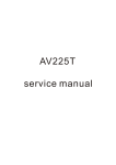
SOME OF THE FOLLOWING
SYMBOLS ARE USED TO
IDENTIFY CONTROLS AND
DISPLAYS ON YOUR CAR.
HORN
LIGHTER
WINDSHIELD
WIPER
LIGHTS OR
HIGH BEAM
1
WINDSHIELD
DEFROSTER
WINDSHIELD
WASHER
1-
AVOID SPARKS
OR FLAMES
#O
FOG LAMP
SPEAKER
a s[i:&
go
4
HAZARD
FLASHER
VENiILTING
A
Q
PROTECT EYES
BY SHIELDING
8
1
ILLUMINATION
CONTROL
--- -
ENGINE
PRESSURE
OIL
CAUTION
POSSIBLE
INJURY
,
ENGINE
COOLANT
TEMPERATURE
TRUNK/
HATCHBACK
RELEASE
DOOR LOCK1
; UNLOCK
RADIO
VOLUME
a
--
.
.. .. . . . a
RELEASE\
HOOb":':
FUEL
,
a
VENT
.
&~
'a
HEATER
.c
.1 -BATTERY--
~
TURN
SIGNALS
WINDSHIELD
p
-
00
"'"
WINDOW
@
SYSTEM
-.,. ,; CHARGING
.'
.8
,
I
,
ENGINE OIL
~ooRAJAR
WASHER
SPARK OR
:LAME COULD
EXPLODE
BATTERY
PE
PARKING
LIGHTS
I
CAUSTIC
BATTERY
ACID COULD
1AUSE BURNS.,
--riii-r--
REAR WINDOW
DEFOGGER
&
FASTEN SEAT
BELTS
4
:-.BEAM
2
5 0
I-
+
I
-
a
MANUAL
Q
TRANS S H I F T
INDICATOR . ' 8 1 F T
.
.
i
INTRODUCTION
3
-
@
fiem
BEFORE DRIVING
YOUR CAR
5. Check that all the warning lights work as
the key is turned to "Run" or "Start."
TRANSAXLE
While reading this manual, you will note many
references to the "transaxle." The transaxle is
a transmission and differential (axle)combined
in a single unit. To avoid confusion, the word
"transaxle" will be used throughout this
manual to refer to both the transmission and
differential functions.
6. Check all gages (including the fuel gage).
7. Release the parking brake (and make sure
the "BRAKE" light turns off).
See related topics in this manual or the Maintenance Schedule booklet, especially if problems
are found.
DRIVER DAILY CHECKLIST
STOWING THINGS IN (OR ON)
THE CAR
Be sure you know how to use your car and its
equipment before operating it.
Before Entering t h e Car
1. See that windows, mirrors, lights and
reflectors are undamaged, clean and
unobstructed.
2. If any tire does not look normal, check it
with a pressure gage.
3. Look for fluid leaks.
4. Be sure everything is properly stowed.
5:Check-the-area-behind
the-car-if-you-areabout to back up.
Before Driving O f f
1. Lock ail doors.
2. Adjust the seat.
3. Adjust inside and outside mirrors.
4. Always properly fasten your seat belt.
Check that seat belts for all other
occupants are fastened properly. Never let
anyone ride any place in or on this vehicle
where there is no seat belt.
- .-- -
-.
SECTION
1
-
CAUTION: To help avoid personal injury
during a collision or sudden maneuver,
always take extra care when stowing
things. Put luggageor cargo in the rear,or
front storage compartment if possible.
Cargo weight inside the car should be
distributed as evenly as possible. Locate
cargo on the optional deck lid luggage
carrier-againstfhe-rear-railsecure. all
items inside the passenger compartment
in place to help keep them from being
thrown about. Do not pile luggage or
cargo inside the vehicle higher than the
seatback. Also see "Vehicle Loading"
under "Tires" in Section 5.
L
.
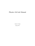
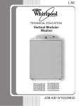
KEYS
"Twodifferent keys are providedfor the locks on
your car. The key code is stamped on the
--
...
~
I
BEFORE D R I V I N G YOUR C A R
I
I
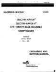
IGNITION
A L L OTHER LOCKS
1-2
DOOR LOCKS
K N O C K OUT PLUGS
.
"knock-out".plug in each key head.
r Key w i t h square head - f o r the ignition
lock only.
r Key w i t h oval head - for all other locks.
For car security:
Record the key code numbers, then knock
the
plugs out of the keys.
.
'
.
::
.
:
.
.
Keep
the key codes in a safe place(such as.
:
.
your wallet), not in the car.
If the original keys are lost, duplicates can be
., made using the key codes. Stamped on the key
\ .', ..
,, ' IS a letter indicating the proper key blank
needed if duplicates are required. Contact any
r GM dealer or a locksmith.
If you park in an attended lot, leave only your
'square-head ignition key. Take the oval.head
key with you.This will help prevent illegal entry
..'
into your car or any locked compartment.
-+
It's a good idea to carry an extra key to the door
in your wallet or purse, should you accidentally
..
lock your regular keys in the vehicle. To help
protect your car and its contents against theft,
General Motors has provided anti-theft features
which would also make it inconvenient and
.possibly expensive to enter the vehicle if you
are locked oui.
'.
-.
'
,;,
Lock doors from inside by sliding the door
lock lever located below the door latch
handle on each door panel.
r Lock doors from outside by first sliding the
lock lever then closing the door.
r Doors can also be locked fromoutside by
<.
usinkthe
oval head kev.
-.
AII modelshave as a standard safety feature
overriding door locks. When the doors are
locked, both the'lnside and outside door latch
mechanisms are inoperative, thus preventing
inadvertent opening of the door by movement
of the inside handle.
A l w a y s L o c k T h e Doors
CAUTION: To help reduce the risk o f
personal injury in an accident, always
(Continued)
1-3
BEFORE DRIVING YOUR CAR
MIRRORS
Inside R e a r v i e w M i r r o r
CAUTION: (Continued)
lock the doors when driving. Along w i t h
using the seat belts properly, locking the
doors helps prevent people from being
thrown from the vehicle. It also helps
prevent unintended opening of the doors
end helps keep out intruders.
P o w e r Door L o c k s (Optional)
All doors may be locked or
unlocked by operating the
switch marked "LOCK," located
on each door trim pad on cars
equipped with power door
locks.The electric locking mechanism does not
at any time interfere with manual operation of
any door lock lever. The doors will not unlock
or open with the inside door handle when the
power door lock swiidh has been actuated, but
can be unlocked individually by sliding the lock
lever.
-----
The mirror can be adjusted up, down or
sideways to obtain the best view. Move the .
mirror lever to the night position to reduce
glare from the headlights of vehicles behind
you.
Outside R e a r v i e w Mirrorfs)
WINDOWS_-
M a n u a l W i n d o w Control-----------___-Door windows can beraised or lowered by
rotating the hand crank located in the door
panel.
Power Windows
Optional power windows will operate only
when the ignition is in "RUN." Aswitch for each
door window is provided on the console. (See
"Console Controls" insection 2D.)
_Adjust the outside mirror(~)so you can just see
the side of vour vehicle. This helm vou
determine the'location of objects seen in the
mirror.
The remote control lever for the left-hand
outside rearview mirror i a located on the
forward sectionof thedriver's interior doortrim
panel. Simply move the lever in the desired
-..
BEFORE DRIVING YOUR CAR
direction to adjust the position of the mirror.
.,
,
'
#
.
The control switch for optional Power Sport
Mirrors is located on the console (see "Console
Controls" in Section 2D). To adjust the mirror,
slide the lower portion of the switch to select
which mirror you wish to adjust, either LEFT or
RIGHT. Then, press the upper portion of the
control switch at that portion of the switch pad
which corresponds to the direction you would
like the mirror to move. Hold the switch pad
down until the mirror has moved to the desired
position.
Convex Rearview Mirror
Your car may have an optional convex outside
right-hand mirror. (A convex mirror has a
curved surface.)
r Use care when judging the size or distance
' :
.' "-',,. of a vehicle or other object seen in this
.
convex mirror - such objects wili look
smaller and appear farther away than
r l
when seen in a flat mirror.
SUN VISOR ADJUSTMENT
Grasp the visor by the rear edge and pull
downward to position ,the visor in the
upper portion of the windshield.
r Remove the visor from its retainer (if
equipped), pull the bottom edge down.
and swing the visor to one side to position
at the side window.
r Adjustment of the screw at the pivot point
will loosen or tighten the visor on its shaft.
SEATS
Adjustment
:
.'
.
!*.
; '.
r! Use your inside mirror(orglance rearward)
to determine the size and distance of
objects seen in the convex mirror.
Adjust the mirror so you can just see the
side of your vehicle.
,
4
,
Visor Vanity Mirror
The optional visor vanity mirror is located on
the upper surface of the right-hand sun visor.
Swing the sun visor down for access to the
mirror.
SEAT F O R W A R D I R E A R W A R D ADJUST-
SEAT BACK R E C L I N E I S E A T B A C K
LATCH RELEASE L E V E R
The seats may be adjusted forward or rearward
by moving the control lev,er located under the
front of the seat. Move the lever toward the left
side of the car to release the locking
mechanism: then exert slight body pressure to
move the seat to the desired position. Release
the control lever to lock the seat in the desired
position.
1-5
BEFORE D R I V I N G YOUR C A R
Adjust Driver's Seat While Parked
while the car is moving. The seat could
move suddenly and cause the driver to
lose control of the vehicle.
After adjusting the seat, push it back and forth
to be sure it will not move. Take the car to your
dealer for service if your seat does not latch.
Reclining Seat
The multi-position reclining seats can be tilted
forward or rearward of the normal position by
exerting rearward pressure on the seatback
and lifting the control lever at the outboard side
of the seat cushion. Release the control lever to
lock the seatback in place.
To returnthe seatback to the upright position,
release pressure on the seatback and lift the
control lever. The seatback will then move
forward.
Seatback Position W h e n Moving
under the lap belt during a collision, an
occupied reclining seat should not be
reclined any more t h m e e d e d - f o r comfort. The seatback and seat belts
provide best restraint only when the rider
is sitting well back and straight up in the
seat. (The lap belt is designed to spread
CAUTION: (Continued)
the force of a collision over the hipbone.
If you are reclined. the lap belt may slide
past your hips and apply restraint forces
directly to the abdomen. Therefore, in the
event of a frontal collision, the risk of
personal injury may increase with
increasing recline of the seatback.)
Do not adjust the reclining seatback on
the driver's seat while the car is moving.
The seatback could move suddenly and
cause the driver to lose control of the
vehicle.
I
-
-
Seatback Latches
The seatback latches are designed to limit
forward movement of the seatbacks. To tilt the
seatback forward, pull up on the latch release
lever on the outboard side of the seat cushion.
The seatback should latch when returned tothe
upright position.
SEAT BELT SYSTEMS
personal injury in collisions or sudden
maneuvers, use the seat belts following
the instructiEiFtthls-section-on-theirproper use. maintenance, and application
with child restraint systems.This includes
pregnant women.
BEFORE DRIVING YOUR CAR
2. To reduce the risk of sliding under the belt
during a collision, position the belt across
your lap as low on your hips as possible
and pull it toward the door to a snug fit so
the retractor can take up slack.
The lapshoulder belt is designed to lock
only during a sudden stop or impact. At
other times it should move freely.
3. If the shoulder belt is too snug:
NEVER:
a Wear a shoulder belt under your arm
nearest the door.
a Use a belt for more than one person at a
time.
a Wear the belts twisted.
a Let the belt system become damaged by a
door or seat.
a Put anything into the opening where the
seat belt passes through the trim panel.
(This may jam the retractoror damage the
belt.)
,
1-6
LapShoulder B e l t
1. Adjusttheseat as needed and sit well back
and straight up. Then pull the belt across
your lap and push the latch plate into the
buckle until it clicks. If the belt is not long
enough to permit this, see "Seat Belt
Extender" following.
A. Pull the shoulder belt out at least 130
millimeters (five inches) so that when
you let go, it returns to your chest.
B. Then pull down on the shoulder belt
the least amount needed to ease
pressure but no more than 25 mm
(one inch) and let go.
I.
BUCKLE
1
4. To get rid of the slack in the belt, pull the
belt out as you did in Step 3A. above.
Keep any shoulder belt slack t o a
minimum. Too much belt slack could
reduce the amount of protection in an
accident because the belt is too loose to
restrain you properly.
5. To unfasten the belt, push the bunon on
the buckle. The retractors should rewind
the belt when the buckle is unlatched. To
BEFORE DRIVING YOUR CAR
1-7
1
If the seat belt or
reminder
does
-. svstem
,
.. niJt
work as described, see your dealer for service.
1.
-.--
~
~
~~~~
~~
~
Seat Belt Inspection
Now and then check that belts, buckles, latch
plates, retractors, reminder systems and guide
loops work properly; look for loose parts or
damage that could keep the restraint system
from doing its job. Replace a belt if the webbing
has been cut or otherwise damaged. Replace
belts in use during all but a minor collision; if
there is any question, replace the belt.
TAKE
SLAC
KEEP
HIP
help prevent damage to the seat belt and
interior trim.' before closina the door be
sure
-.- the belt is fully retracte; and the latch
plate IS out'of the way.-.
Seat Belt Extender
If the seat belt cannot be fastened because it is
not long enough, General Motors will be
pleased to furnish a seat belt extender without
charge. Contact your dealer; remember to bring
the heaviest coat expected to be worn to obtain
the proper length extender. Remember that the
extender intended for this car may not be safe
for use in another vehicle and that the extender
from another vehicle may not be safe for use in
this car. For example, an improper extender
might come apart during an accident causing
the user to be injured. Do not use the extender
whenever the seat belt can be fastened without
it.
-
Seat Belt Reminder
When the key is turned to "Run"
or "Start," a light will come on
for four to eight seconds to
remind people to fasten their
seat belts. Unless the driver's
seat belt is buckled, a buzzer or chime will
sound at the same time.
la
To use the extender, push the car's seat belt
latch plate into the extender's buckle, and the
extender's latch plate into the seat belt buckle.
To unfasten the belt, push in the button in the
center of the extender buckle so that it remains
attached on the inboard side. This helps avoid
damaging the extender or interior trim. Keep
the extender in the vehicle for which it was
intended.
*..y,
BEFORE DRIVING YOUR CAR
CHILD RESTRAINT
All vehicle occupants and especially children
should be restrained whenever riding in cars.
Holding a child in your arms is not a substitute
for a child restraint system. In an accident, a
child held in a person's arms can be struck or
crushed by any unrestrained rider. An unrestrained child could also be injured by striking
the interior, or by being ejected from the
vehicle during a sudden maneuver or impact. A
child restraint system can help protect a child
in a car.
in using any child restraint system, be'sure to
read and follow all instructions on installation
and use that come with the system.
Child R e s t r a i n t With T o p S t r a p
Should you choose to use a top-strap-equipped
child restraint in this vehicle, you may either
want to have your Pontiac dealer install the top
strap anchor bracket, or learn from the dealer
where to attach it. (The anchor bracket is
e"- supplied by the company that makes the child
restraint system.)
1-8
R i d i n g W i t h o u t A C h i l d Restraint
W h e r e P e r m i t t e d By L a w
Note that some form of child restraint is now
mandatory in all fifty states (most provinces in
Canada). For the best protection in an accident
or sudden manuever, children small enough for
child restraint systems should be restrained
that way if at all possible to do so correctly.
However, the following may provide some
degree of protection for such children if a child
restraint is not used.
0 Infants whocannot sit up should be placed
in a padded baby carrier. Put it crossways
on the car seat and securely restrain itwith
the car's lap belts.
0 Achild who can sit up by itself should wear
both lap and shoulder belt. If the shoulder
belt irritates the neck or face move the
child closer to the center of the car.
Never let a child stand or kneel on the seat.
STARTING AND
OPERATING
ENGINE EXHAUST GAS
CAUTION (CARBON
MONOXIDE)
CAUTION: Do not breathe exhaust gas
because it contains carbon monoxide,
which by itself has no color or odor.
Carbon monoxide is a dangerous gas. It
can cause unconsciousness and can be
lethal.
If at any time you think exhaust fumesare
1 entering the car, have the cause determined and corrected as soon as possible.
If you must drive under these conditions,
drive only with ALL windows fully OPEN.
Protect against carbon monoxide entry
into the car body. The best way is to keep
the engine exhaust system, car and body
ventilation system properly maintained.
We recommend that the exhaust system
and body be inspected by a competent
'technician:r each time the car is raised for an oil
change;
r whenever a change is noticed in the
sound of the exhaust system;
r whenever the exhaust system,
underbody or rear of the car is
damaged or becomes corroded.
See your Maintenance Schedule booklet
for parts requiring inspection.
(Continued)
'
SECTION
2
:AUTION: (Continued)
'o allow proper operation of your car's
entilation system, keep the air inlet grille
n front of the windshield clear of snow,
mves or other obstructions at all times.
)o not perk with the engine running or
jle this car for more than 10 minutes
vith the ventilation system control
witch in the "OFF" position. Even with
he ventilation system on. running the
ngine while parked or stopped for longer
~eriodsof time is not recommended. Entry
I carbon monoxide into the car body is
~ossiblewith a poorly repaired, damaged,
Ir corroded exhaust system or car body.
)O not run the engine in confined areas
such esgarages or next to a building) any
nore than needed to move the car. When
hecar has to be stopped in an unconfined
rea with theengine running for any more
han a few minutes, take the following
teps:
A. Adjust the heating or cooling system
tTfoTce-outside'air-into-the-car-asfollows:
1. On cars not equipped with air
conditioning, set the fan to
medium or high speed.
2. On cars equipped with air conditioning, set the fan to an intermediate or high speed and press
one of the upper buttons not
marked "OFF" or "MAX."
(Continued)
STARTING A N D OPERATING
:AUTION: (Continued)
B. Keep the exhaust tailpipe area clear
o f snow and other material to help
reduce the buildup of exhaust gases
under the vehicle. This is particularly
important when parked in blizzard
conditions.
h i v i n g w i t h the trunk lid open is not
ecommended. Under some conditions.
~xhaustgases may be drawn into the car.
f the trunk lid must remain open for some
eason while moving, or if electrical
iring or other cable connections to a
railer must pass through the seal
letween the trunk lid and the body, follow
hesa precautions:
0 Close all windows.
0 Adjust the heating or cooling system
t o force outside air into the car as
described above, but set the fan t o
high speed.
NEW CAR "BREAK-IN"
PERIOD
You can drive your new car from its very first
mile/kilometer without following a formal
"break-in" schedule. However, there are things
you can do during the first fewhundred miles/
kilometers of driving that will add to the future
performance and economy of your car.
'%.
.i,
.+
\r
:
We recommend you limit yourspeed during the
first 500 miles (800 kilometers) to a maximum
of 55 mph (90 km/h); but do not drive for long
periods at any one constant speed, either fast
or slow. During this time, avoid full throttle
2-2
starts and, if possible, avoid hard stops especially during the first 200 miles (320 kilometers) of driving.
Always drive at moderate speed until the
engine has completely warmed up.
If you plan to use your new car for trailel
towing, see the following.
TRAILER TOWING
This car is designed and intended to be used
mainly to carry people. Towing a trailer will
affect handling, durability and economy. Your
safety and satisfaction depend upon proper
use of correct equipment. Also, you should
avoid overloads and other abusive use.
The maximum loaded trailer weight you can
pull with your car is 450 kilograms (1000
pounds). The maximum static tongue weight
should not exceed 45 kilograms (100 pounds).
Information on trailer towing ability, special
equipment required, and optional equipment
available should be obtained from your dealer.
Or, write: Pontiac Motor Division, Customer
Services Department. One Pontiac Plaza,
Pontiac, MI 48053.(In Canada, writeto General
Motors of Canada Limited, Customer Services
Department, Oshawa, Ontario L l J 526.)
Tires
When towing trailers, be sure your tires are
properly inflated to the inflation pressure
shown on the Tire Placard on the driver's door.
The allowable passenger and cargo load for
this car, also shown on the Tire Placard, is
reduced by the trailer tongue weight wh'enever
the trailer is attached to thk car.
. See Section 5
for more tire informatib.
'
STARTING AND OPERATING
Maintenance
More frequent service is required when using
your car to pull a trailer. See the Maintenance
Schedule booklet for Automatic Transaxle
Fluid and Engine Oil change requirements for
trailering.
Now and then, check that all trailer hitch bolts
and nuts are tight. Also see the Maintenance
Schedule booklet, and the Index in this manual,
for important facts on belts, cooling system
care and brake adjustment.
B r e a k h Schedule
See the new car break-in information in this
manual. Also, we recommend you drive your
new car for 500 miles (800 kilometers) before
trailer towing. At the end of this 500 mile (800
kilometer) break-in period, avoid speeds over
50 mph (80 km/h)and full throttle startsduring
the first 500 miles (800 kilometers) of trailer
towing.
CAUTION:
HITCHES .'lo help avoid personal injury
due to s' ay caused by such things as
crosswi,,. ..large trucks passing or road
roughnebs,-or-due-to-a.separation:~o=
trailer:
' r . Keep the trailer tongue load at 10
percent of the loaded trailer weight.
Tongue loads can be adjusted by
proper distribution of the load in the
trailer. This can be checked by
weighing separately the loaded
trailer and then the tongue.
(Continuedl
&
.
.
-.
2-3
:AUTION: (Continued)
Do not attach any hitch to the
bumper bar on this vehicle. A hitch
anachment may be made through
the bumper mounting attachments
but only if an additional attachment
is also made.
r Do not use any type of weight
transfer hitches on your car.
r Do not mount hitch to the subframe
as this may result in damage to the
car.
Do not allow steel hitch parts to be in
direct contact with aluminum
bumper parts, if so equipped. When
steel and aluminum are in contact, a
galvanic reaction (a form of
corrosion) can occur which will
progressively lessen the strength of
the contacting metals to the point of
failure. An organic compound or paint
should be used as a barrier on the
-contact/ng-surface6
and on the
attaching fasteners.
r When y& remove a trailer hitch, be
sure to seal any mounting holes in the
body. This will help prevent entry of
exhaust fumes, dirt or water. See
"Engine Exhaust Gas Caution
(Carbon Monoxide)" at the beginning
of this section.
STARTING AND OPERATING
TRAILER TOWING TIPS
Getting Started
Before entering traffic with a trailer that has
electric brakes, start the car and trailer moving
and apply the trailer brakes by hand to be sure
the trailer brakes are working and the trailer
electrical system is connected.
Engine Cooling
If your engine overheats, follow the steps under
"Engine Cooling System Overheating" in
Section 3.
.'
D o w n Steep o r Long Grades
.
Before going down a steep or long grade.
reduce speed and shift the transaxle into a
lower gear to help control your car's speed. Try
not to hold the brake pedal down too long or
too often. This could cause the brakes to
overheat and reduce brakg effectiveness.
Transaxle
..
See the method for checking the transaxle fluid
level in Section 5.
-
FUEL REQUIREMENTS
Your gasoline (spark ignition) engine is
designed to use only unleaded fuel that meets
ASTM specifications. Unleaded fuel must be
used for the emission control:systems to
operate properly. Its use will also reduce spark
plug fouling, exhaust system corrosion and
engine oil deterioration. Use of fuels not
meeting ASTM specifications could cause poor
-&e!erformance and increase emissions.
Damage caused by the use of ieadedor other
improper fuel is not covered by the New
24
Vehicle and Emission Control Systems Warranties. The effectiveness of the catalytic
converter decreases after use of as little as one
tank of leaded fuel. Also, your car may have the
Computer Command Control System, which
includes an oxygen sensor. Leaded fuel will
damage the sensor, and deteriorate emission
control. (For more information, see "Computer
Command Control System" in Section 5 of this
manual.)
Federal regulations require that pumps
delivering unleaded fuel be labeled with the
word UNLEADED. Only these pumps have
nozzles which fit the filler neck of your car fuel
tank.
In the United States, Federal law also requires
that fuel octane ratings be posted on the
pumps. The octane rating shown is an average
of the Research (R) octane and Motor (M)
octane numbers. In most parts of the United
States, vou should use unleaded fuel with.an
octane rating of at least 87. However, you may
use unleaded fuel with an octane rating as low
as 85 in these high-altitude areas: Colorado.
Montana. New Mexico, Utah,' Wyoming,
northeastern Nevada, southern Idaho, western
South Dakota; and Texasdirectly south of New
..
Mexico.
.
Using unleaded fuel with an octane'rating
lower than stated above can cause persistent,
heavy "spark knock." ("Spark k n o c k is a
metallic rapping noise.) If severe, this can lead
to engine damage. If you detect heavy spark
knock even when using fuel of the.recommended octane rating, or if you hear steady
spark knock while ho1ding.a 'steady speed on
level roads, have your Eontiac dealer correct :
the problem. Failure to take steps to stop such
,. '*.
., . : "..
.
STARTING AND OPERATING
knocking is misuse of the vehicle, and damage
due to misuse is not covered under the New
Vehicle and Emission Control Systems Warranties.
However, now and then you may notice light
spark knock for a short time while accelerating
or driving up hills. This is no cause for concern
because you get the greatest fuel economy
benefit from the fuel's octane rating when
there isoccasional light spark knock. Using fuel
with a higher octane rating than that which
allows occasional spark knock is an unnecessary expense.
Fuels Containing Alcohols
Unleaded fuels composed of blends of
gasoline and alcohol (ethanol, methanol, cosolvents) are available. Some fuel suppliers voluntarily use labels of the type shown below to
inform consumers that their gasoline contains
alcohol. Also, some states require the use of
such labels. If you are not sure whether there is
alcohol in.the fuel you buy, ask the service
station operator.
. ...
--I
and Emission Control Systems Warranties.
DO NOT use fuels containing more than 5
percent methanol under any circumstances.
Fuel system damage or car performance
problems resulting from the use of such fuels
are not the responsibility of Pontiac Motor
Division and are not covered under the New
Vehicle and Emission Control Systems Warranties.
.,
Fuels containing 5 percent or less methanol
(methyl or wood alcohol) may be suitable for
use in your car, if they also contain sufficient
quantities of appropriate cosolvents to prevent
phase separation (according to proposed
ASTM specifications), and ingredients. to
protect your car's fuel system against corrosion
of metals and damage to plastics and rubbers
caused by methanol. However, the suitabilityof
these fuels is not fully known at this time.
Check with the service station operator if you
have any questions regarding whether the fuel
contains appropriate cosolvents and corrosion
inhibitors.
?
-Methanol-
E
2-5
t
h
Cosohrent
3a
n
o
l%
%
I
-
You may use properly blended fuels containing
10 percent or less ethanol (ethyl or grain
alcohol) and still becovered by the New Vehicle
If you are not satisfied with the vehicle driveability and fuel economy provided by fuels
containing alcohols, you may prefer to use
unleaded gasoline that does not contain
alcohol.
-.
-
.;
STARTING A N D OPERATING
OPERATION IN FOREIGN
COUNTRIES
Your car requires unleaded fuel which may not
be available in other countries.
Before taking your car to a foreign country,
checkto see if the proper fuel is available. Most
major oil companies or domestic auto clubs
should have this information. Foreign offices of
major oil companies or auto clubs may also be
of help. Be aware that use of leaded fuel or use
of fuel that has a lower octane rating than is
required by your vehicle will cause the
emission control system to lose its effective. .ness and can cause engine knock or serious
engine damage. Neither GM lnternational
Export Sales nor Pontiac will be responsible for
damage to your vehicle as a result of using the
improper fuel.
General Motors Corporation
lnternational Export Sales
Service Department
Room 3-132
General Motors Building
Detroit, Michigan 4 8 2 0 2
(313) 5 5 6 - 4 8 6 2
When writing, please include:
r the Vehicle Identification Number and
r the countries in which you plan to travel.
2-6
If you intend to take your car outside the U.S.
or Canada, contact the GM International Export
Sales Service Department at the following
address, to find out what you must do in order
to operate your car in other countries, or for
additional information and a copy of the appli.
cable maintenance schedule.
IMPORTANT FACTS YOU
SHOULD KNOW ABOUT FUEL
ECONOMY AND HOW TO
IMPROVE IT
How you drive, where you drive, and when you
drive all affect how many miles/kilometers you
can get from a gallon/liter of fuel. You can save
fuel if you avoid "Jackrabbit" starts, maintain
as constant a throttle position as traffic conditions allow once you have reached cruising
speed, and avoid sudden stops which waste
energy in the form' of heat generated in
braking. Frequent short trips, excessive idling
and use of the air conditioner in cool weather
(when. "Vent" would provide' adequate
comfort), all can contribute to decreased fuel
economy.
. .
The careful anention you give your darasfaras
maintenance and repairs are concerned will
also help fuel economy. Proper engine and air
cleaner maintenance, lubrication intervals,
wheel alignment and tire inflation pressures,
when closely adhered to, will pay dividends in
improved fuel economy as well as longer
vehicle life.
STARTING A N D OPERATING
Fuel Selection
Use only unleaded fuel meeting the octane
ratings given under"Fue1 Requirements" in this
section of the manual. Unleaded fuel must be
usedforthe emission control system to operate
properly. Leaded fuel will damage the
Computer Command Control system oxygen
sensor, and reduce the effectiveness of the
catalyst and affect emission control. Using
leaded fuel can also damage other pans of the
emission control system and could result in
loss of emission warranty coverage.
2-7
NOTICE: (Continued)
to 15 seconds before trying again. This
will help prevent damage t o the starter.
I
COLD OR W A R M ENGINE. With
your foot off the accelerator pedal.
crank the engine by turning the
ignition key to "Start." Release the
key when the engine starts. It is not
necessary to push down the accelerator pedal.
STARTING THE ENGINE
1. Apply the parking brake.
2. Automatic Transaxle - Shift the transaxle
to Park or Neutral (Park preferred). A
starter safety device is designed to keep
the starter from operating if the shift lever
is in any drive position. (If you need to
re-stanthe engine while the car is moving,
shift the transaxle to Neutral.)
Manual Transaxle - Push the clutch pedal
to the, floor and shift the transaxle to
Neutral. Hold the clutch pedal to the floor
while you are starting the engine. A starter
safetv device is desianed
to keeo the
"
---start$~.from.ope~ating
if the clutch pedal is
not pushed down all the way.
3. start the engine as outlined below for
different conditions.
than about 15 secondsat a time. Wait 10
If the engine does not start, or starts
but fails to run, repeat this procedure.
4. Apply the regular brakes and shift into the
proper gear. Release the parking brake
and drive off.
If Engine Fails t o S t a r t A f t e r N o r m a l
S t a r t i n g Procedure
1. If you tried the Cold or Warm Engine
starting procedure and the engine still
does not start, push the accelerator pedal
down to the floor and hold it there while
cranking the engine. This should clear the
-engine.if.it.isflor&d.
2. If the engine has been flooded with too
much fuel, it may start to run but not have
enough power to keep running. In that
case, continue cranking with the accelerator pedal all the way to the floor until
the engine clears itself of excess gasoline
and runs smoothly.
?
f:;
<'.
I NOTICE:
Do not crank more than 15
seconds at a timeor y& could damage the
starter.
I
-
-
1
I
3. Keep items that may appear to be of value
out of sight and locked up when possible.
4. Lock all doors.
After starting, the idle speed will automatically be reduced as the engine warms up.
GUARD AGAINST THEFT
PARKING
- Your new Fiero has many features to help
I
prevent theft of the car, its equipment, and
contents. But these anti-theft features depend
upon you to work.
,
The time to be most on guard is when leaving
the car:
1. Park in a lighted spot when you can, and
fully close all windows and any roof
panels.
r Be sure to turn your steering wheel
sharply to one side to help prevent
towing of this vehicle from the rear.
2. Lock the steering column and take the key:
-
c,
i,
::(
5.* : .
.I
I
.
:
.
Turn the key to "Lock while
depressing the key release lever (if so
equipped) and remove the key. This
locks the ignition and both steering
and shiftcontrols, unless your manual
transaxle car has a key release lever.
In that case, the shift control is not
locked. The key can be removed only
when the ignition is locked.
r If you must leave a key with the car,
leave the square-head key only. Take
the oval-head key with you. This will
he!p prevent unwanted entry into
your-car or any locked compartment.
:AUTION: Before the driver leaves this
ehicle, t o reduce the risk of personal
ijury as a result of vehicle movement:
1. Firmly apply the parking brake.
2. Shift the automatic transaxle to Park
or the manual transaxle to Reverse.
3. Turn the key t o "Lock." On cars with
manual transaxles, depress the key
release lever and turn the key to
"Lock."
4. Remove the key (the buzzer or chime
is dasigned to remind you).
5. Be sure the car is not moving before
you leave the driver's seat.
'o reduce the chance of personal injury
nd vehicle damage due to engine over.
eating, never leave the engine.'idling
vithout an alert driver present. If the
ngine should overheat as indicated by
he Engine Coolant Temperature gage,
m e d i a t e action is required to.correct
he condition. Continued operation of the
ngine even for a short time may result i n
fire.
STARTING AND OPERATING
car over combustible materials, such as
grassor leaves. They could touch the hot
exhaust system and start a fire.
TRANSAXLE
Descending a Grade
CAUTION: To reduce the risk of personal
injury, before going down a steep or long
grade reduce speed and shift the
automatic trensaxle t o low or manual
transaxle t o next lower gear. Do not hold
the brake pedal down too long or too often
whilegoing downhill. This could cause the
brakes toget hot and not work as well. As
a result the car will not slow down at the
usual rate. Failure t o take these steps
could result in loss of vehicle control.
2-9
open-type automatic transaxle equipped cars.
When the clutch engages, for example, you
may notice what feels like an extra transaxle
shift. Also, on occasion, you may feel certain
incidental engine pulsations in the 3 0 to 50
mph (50 to 80 kmlh) range. This feel is similar
to that sometimes experienced in a manual
transaxle equipped car. In addition, when the
accelerator pedal is released abruptly, you may
feel a slight impulse before the clutch disengages.
These conditions are normal. They have no
adverse effect on your car and do not indicate
the need for repairs.
Automatic transaxle shift indicators are
arranged with "P" (Park) at one end,followed in
sequence by "R" (Reverse). "N" (Neutral), and
the forward driving ranges. Push in the shift
lever button when shifting into or out of Park
and Reverse. (See "Console Controls" in
Section 2D.)
P (Park) - For starting the engine andlor
holding the car in locked position.
Automatic Transaxle
Your automatic transaxle has a clutch-type
-tolque
converter. The clutch is designed to
engage when the car reach?ZXsteadyspeed of
25 mph,(40 kmlh) or higher depending on the
particular model. When engaged, the clutch
provides a direct connection between the
enaine
and the drive wheels. This direct
- connection allows for more efficient operation
of the transaxle and thereby. helps
. contribute to
improved fuel economy.
~
~
-
R (Reverse) For backing the car.
N (Neutral1 - An alternate position for
starting engine.
D (Drivel - For all normal forward driving.
2 - For engine braking when descending
moderate grades.
~
~
With the clutch-type converter, you may notice
some. operational differences compared to
1 - For engine braking when descending
steeo- arades
when road sians reauire use
"
of'low (First) sear." Do not exceed 40
mph (60'kmlh)in low (First) gear.
~~~
~
-
-. -
STARTING AND OPERATING
IOTICE: The following practices could
B S U in
~ automatic transaxle failure:
a Shifting between forward and
reverse driving range while operating
the engine at high speed or heavy
throttle, such as when the driving
wheels are on snow or ice
commonly called "rocking." (See the
correct method for "rocking" a car
under "Freeing Car from Sand, Mud.
Snow or Ice" in Section 3.)
a Shifting t o "R" (Reverse) or any
forward range while operating the
engine a t high speed in "N" (Neutral)
or " P (Park).
a Shifting t o " P (Park) while the car
wheels are still turning.
a Operating the transaxle at or near
"stall condition" for more than 1 0
seconds a t a time. ("Stall condition" is
when the engine is running at high
speed while the transaxle is in a
driving range and the drive wheels
aren't moving, such as when stuck in
deep sand or when the car is against
a fixed barrier.)
a Holding car on an upgrade with the
accelerator pedal. (Use the regular
brakes t o hold car on an uphill grade.)
-
M a n u a l Transaxle
The
console-shift
manual
transaxle shift pattern is
illustrated on the console
adjacent to the shift lever (see
2-10
"Console Controls" in Section 20 of this
manual). Operation of the transaxle is as
follows:
First Gear (1) - Press down the clutch
pedal, shift into First gear, and smoothly
release the clutch pedal while pressing on
the accelerator pedal. This car has a fully
synchronized First gear and may beshifted
into First gear with the car in motion below
20 mph (30 km/h). If the car is completely
stopped and it is difficult to shift into First
gear, release the clutch momentarily with
the shift lever in Neutral, and then shift into
First gear.
Second Gear (2) Press down the clutch
pedal while releasing the accelerator
pedal; then, move the shift lever into
Second gear. Release the clutch pedal and
press down the accelerator pedal as
above.
Third Gear (3) Shift into Third gear as
- described
for Second gear. Slowly release
the clutch pedal and pressdown the accelerator pedal.
Fourth Gear (4)-Shift into Fourth gear as
described for Second and Third gears.
Slowly release the clutch pedal and press
down the accelerator pedal.
Fifth Gear (5) -On models equipped with
a 5-speed manual transaxle, shift into Fifth
gear as described for Fourth gear. Slowly
release the clutch pedal and press down
the accelerator pedal.
To Stop Release the accelerator pedal
and press down the brake pedal. Just
before the car stops, press down the
clutch pedal along with the brake pedal
-
-
-
STARTING AND OPERATING
2-1 1
and move the gear shift lever to Neutral.
Neutral (N) . For use when starting or
idling the car.
Reverse (R) The car must be brought to
a complete stop before shifting into
Reverse. Press down the clutch pedal and
shift into Reverse.
Four-Speed:
r Press down the clutch pedal.
r Shift into Neutral.
0 In one continuous motion, move
the shift lever from right to left(in
Neutral) and then forward into
Reverse.
r Release the clutch pedal slowly
while pressing down the accelerator pedal.
Five-Speed:
0 Press down the clutch pedal.
r Shift into Reverse. (When
shifting from 5th gear to
Reverse, you must first move the
shift lever to the neutral ''3-4"
position, then to Reverse.)
0 Release the clutch pedal slowly
needed, accelerate as desired and shift when
the light goes on.
Downshifting one or more gears may be
required to keep the engine running smoothly
or to maintain satisfactory performance. When
downshifting to a lower gear, the light may
come on for a moment if the accelerator pedal
is not released completely. Disregard this light
during a downshift.
The onboard computer makes the " S H I T
light work. This computer knows how fast the
engine is going and how hard it is working, how
fast the car is going, and how far the accel.
erator is pressed down. It uses this information
10 times every second to decide if you could
get better fuel economy by shifting to the next
higher gear.
When the accelerator is released, it is normal
for the light to be off.
While accelerating, it is normal for the light to
go on, off, and on again if you quickly change
the position of the accelerator. In essence, if
you change your mind, it will too and it will
respond very quickly.
lNlS
-
If your car has a manual transaxle, there is a
"SHIFT light on the instrument panel. This
light will show you when to upshift for best fuel
economy at any acceleration.
When this light is on, shift your transaxle to the
next higher gear if weather, road and traffic
conditions permit. For maximum fuel
economy, accelerate slowly and shift when the
light goes on. When more performance is
VOTICE:
following operating precau-- -The
. . - -:ions should be observed:--r Do not "speed shift"; allow time
between shifts for the transaxle
synchronizers t o coordinate.
Use only First gear to accelerate from
a stop.
(Continued)
4
STARTING A N D OPERATING
NOTICE: (Continued)
Always place the shift lever in
Neutral when starting the engine.
Never leave the cer unattended with
the engine running.
a Always set the parking brake firmly
before leaving the car.
a Do not coast in Neutral (illegal in
many states).
a Never "ride" the clutch pedal: this
will cause excessive slippage with
resultant wear on the clutch Darts.
BRAKING AND STEERING
TECHNIQUE
To get maximum braking while maintaining
vehicle control, use a "squeeze" braking
technique. Do this by pushing on the brake
pedal with steadily increasing pressure. If
possible, steer around obstacles when there is
not enough room to stop. If the vehicle doesn't
respond to steering or changes direction when
you are not steering, ease up on the brake
2-12
pedal. If the frontwheels are not rolling to some
extent, you cannot control the direction of the
vehicle by turning the steering wheel. To
correct for a skid, ease off the gas pedal or the
brake and steer to keep the vehicle pointing
where you want it to go. Don't touch the brake.
Driving o n Slippery Surfaces
Drive, steering, 'and braking traction are
reduced when water, snow, ice, gravel, or other
material is on the road. Slow down and adjust
your driving to such conditions. It is important
to slow down when it is slippery because
stopping distance will be longer and vehicle
control more limited. Whiledriving on a surface
with reduced traction, avoid maneuvers
involving sudden steering, acceleration, or
braking (including engine braking due to
shifting to a lower gear), which could cause the
tires to skid. You may not realize the surface is
slippery,,until the vehicle is skidding. Learn to
recognize warning clues - such as enough
water. or ice on the road to make a "mirrored
surface" - and slow down when there is any
doubt. Also see "Traction" under Tires in
Section 5.
STEERING COLUMN
CONTROLS
SECTION
2A
-
STEERING C O L U M N CONTROLS
ANTI-THEFT STEERING
COLUMN LOCK
3
The anti-theft lock (ignition)on the right side of
the steering column has five positions:
0 Accessory - You can use some electrical
accessories when the engine is not
running. To engage this position, push in
the square-head key and turn the top of the
key toward you.
Lock- Normal parking position. It locks the
ignition and prevents normal use of the
steering wheel and shift controls. The
ignition key cannot be turned to"Lock
and removed until the shift lever is moved
to " P (Park) on automatic transaxle
models (shift to "Reverse" on manual
transaxle models). If you have a manual
transaxle. "Lock prevents normal use of
the steering wheel. The ignition key
cannot be turned to " L o c k without
pressing down the key release lever.
r Off - You can turn off the engine without
locking the steering wheel and shift
controls.
r Run - Normal operating position.
r Start - Cranks the engine.
CAUTION: On manual transaxle cars, if
you need t o turn the engine off while the
car is moving, do not press the key release
lever. Turn the key only t o "Off." Turning
the key t o "Lock" will lock the steering
column end result in loss of abilitv t o steer
this car.
2A-2
If you have trouble turning the key to unlock the
ignition,first be sure the key is pushed in all the
way. Then, try to turn the steering wheel as
hard as you can inthe direction the wheels are
turned. At the same time, turn the ignition key
with as much effort as you can apply with your
hand. Do not try to use a tool of any kind to
apply more force on the lock knob,as this could
break the knob.
TILT STEERING WHEEL
This optional steering wheel can be adjusted
by lifting the control lever on the left side of the
steering column, placing the wheel in the
desired position and then releasing the lever.
There are six positions: three above center, one
center position, and two below center. In order
to provide easy entry or exit from the vehicle,
the wheel should be moved to its uppermost
position when leaving the car.
'
I
HAZARD WARNING FLASHER
The Hazard Warning Flasher is
covered in Section 3.
TURN SIGNAL AND MULTIFUNCTION LEVER
The turn signal lever on the left side of the
steering column also controls headlight
low-beam and high-beam, the windshield .
wipedwasher, and the optional Cruise Control.
(For Cruise Control operation, see "Cruise
Control" in this section.)
.
2A-3
STEERING COLUMN CONTROLS
T u r n Signal
I
Move the lever up to the second
stop to signal a right turn. Move
it down to the second stop to
signal a left turn. When the turn
is completed, the signal will
cancel and the lever will return to horizontal.
E3
Lane Change Signal
In some turns, such as changing lanes, the
steering wheel is not turned far enough to
cancel the turn signal. For convenience, vou
can flash the turn signal by moving the 'lever
part way (to the first stop) and holding it there.
The lever will return to horizontal when you
release it.
..
A green light on the instrument panel is
designed to flash totell you that the front and
reavturn signal lights are working. If the light
stays on,'.bui!'&e's.
not flash, check for a
burned-dut t t r n signal bulb. If the green light
does not come on when you move the lever, .
check the fuse and indicator bulb.
~ e a d l i ~ h t - ~ eChanger
am
With the-headlights on, pull the lever toward
you-until'you-hear-adick~then.release.it.-Thelights will change from low-beam to high-beam
or from high-beam to low-beam. When the
high-beams are on, a light will appear on the
instrumentoanel.
-~
Standard Windshield Wiper
The standard windshield wiper
systemcontrols are on the band
marked ."WIPER on the turn
signal lever.
a For a single wiping cycle, turn the band
toward you. Hold it there until the wipers
begin wiping; then release it. The wipers
will stop after one cycle. For several
cycles, hold the band in place as long as
needed.
.
, For
. . - at low sDeed, turn the
band away from you to the'first stop. For
high-speed wiping, turn the band to the
next stop. Turn the band back to " O F F to
turn off the wipers.
Controlled Cycle Windshield W i p e r
The optional Controlled Cycle
windshield wiper system lets
you vary the wiper speed from a
16-second delay between
sweeps up to the normal low
and high speeds of the standard wiper. .
a The Controlled Cycle wipers work the
same as the standard wipers, except for
the delay feature. To use the wipers with
a delay between sweeps, turn the band on
the turn signal lever to "ON."
r Turn the "Wipe Delay" band away from
you to control the amount of delay. The
w i p e r s will move more often the closer the
band is to "LO." T ~ i C f i i l l y t F t l i e - f i r s t
stop for steady wiping at low speed.
Windshield Washer
To spray washer fluid on the
windshield, push the "paddle"
on top of the turn signal lever.
(This will also turn on the
low-speed wipers.) The s ~ r a v
will continue as long as you hold in the paddld.
.
' . I .
.. *
.'.?-
..
.
.'
STEERING C O L U M N CONTROLS
After using the windshield washer on the
standard w i ~ e svstem,
r
turn the band back to
"OFF to turn off'the wipers.
With the Controlled Cycle wiper system, the
wipers will stop (or return to the action for
which they were set)after completing the wash
cycle.
2A-4
Within the limits of your engine, you can hold
a speed of about 3 0 mph (48 km/h) or higher.
. You can also resume a preset cruising speed
after braking, without using the accelerator
pedal or you can accelerate from a preset
soee,j,
The controls are part of the turn signal lever.
The "Cruise" switch on the bottom edqe of the
Ooeratino Tios
Clear ice or packed snow from the wiper turn signal lever must be moved to "o? before
blades before usingthe wipers,
carefully the system will work. The " S E T button is in the
end of the turn signal lever. There is no Cruise
loosen or thaw wipers that are frozen to
Control engagement below 25 mph (40 km/h).
the windshield or lower molding.
0 Check the washer fluid level regularly. Do
T o ~ n g a g ae t C r u i s i n g Speed
it often when the weather is bad.
Accelerate to the aesired speed, move the slide
-.
Use a fluid such as GM Optikleen to help
lever to the "ON" position, push in the " S E T
prevent freezing damage, and for better
buttonall the way and releasgit slowly. Take
cleaning. Be sure to put the fluid in the
your footoff the acceleiator.pedal and the set
proper reservoir.
.speed will be'maintaine!;j$o~,down
hill. The
Fill the washer fluid reservoir only 3/4 full' , Cruise C h r o 1 . i ~designeN'fi&ci(sengage when
you apply the brakes. flodiiengageth6sy$tem
during the winter to allow forexpansion if
wiihout'coming to a cornplete:&_d;push
the
the temperature should fall low enough to
:,
freeze the solution.
.brake.pedal lightly; use just enough force to
disengage the system, withoui &opping the
: a- '..
0 . - Do not use radiator antifreeze in the wind.
.,
car.),
shield washer; it could cause paint
F
damage.
T o c h a n g e Cruising Speed
r In cold weather, warm the windshield with
To reset the Cruise Control to a faster speed,
the defroster before using the washer, to
move the slide lever to the "R/A (Resume/
help prevent icing that may block the
Accelerate)
position and hold. Vehicle speed
driver's vision.
.: " .'
will increase at a slow controlled rate. Release
the slide lever when the desired higher speed
CRUISE CONTROL,
is reached.
Cruise Control is an optional speed control
... .
To reset to a slower speed, push in the " S E T
system. It lets you keep a constant forward
button all the way and hold it there. Wait until
speed during most normal driving without
thecar slows to the desired speed, then release
keeping your foot on the accelerator pedal,
the button slowly.
thus increasing your comfort on long drives.
'..
6..
--
,
" .
,
-&,,.
STEERING COLUMN CONTROLS
TepUpAepDown
The TapUpKapDown feature allows you to
adjust the cruising speed in 1 mph (1.6 km/h)
increments with the touch of a finger. To
increase the speed, move the slide lever to the
"WA" (Resume/Accelerate) position and
quickly release the slide lever. To decrease
speed, push in and quickly release the " S E T
button.
To "Resume" a Pre-Set Speed
After braking or stopping the car, you can
"resume" your last set cruising speed by accelerating to 25 mph (40 km/h) or more and
sliding the cruise switch lever to ' W A
(Resume/Accelerate) and hold in for about one
second; when you release the " W A (Resume/
Accelerate) switch, your car will accelerate to
the cruising speed set before braking or
stopping.
To Disengage
Disengage the Cruise Control by pushing the
brake or clutch pedal. Though not usually
necessary, you can also turn off the system by
moving the "Cruise"switch to "Off." Holding in
the engagement button until car speed falls
-below-25-mph~(40-km/h),-will-also-disengagethe system.
To Pass A Vehicle
Usethe accelerator pedal for more speed when
passing. When you take yourfoot off the pedal,
the car will slow down to the speed set before
passing.
2A-5
IIOTICE: To help keep the car under
antrol, do not use the Cruise Control and
~articulerly its RESUME-Accel. feature
mder the following conditions:
a When the previously set speed is
fester then the existing traffic flow.
When it is not possibleto keep the car
at a set speed.
On slippery roads, such as those
covered with snow end ice.
On winding roads, in heavy or varying
traffic volume, or in traffic that varies
in speed.
tfter accelerating to the desired speed
~ n engaging
d
the Cruise Control. the car
ill hold a set speed end will not slow
lown when you take your foot off the
lccelerator pedal. To slow the car. follow
:he instructions under "To Disengage."
Nhen going up or down hills. it is possible
or thecerto lose orto gain speed fperticuarly when towing a trailer), even though
he Cruise Control is engaged. If this
lappens while going uphill, merely
lepress the accelerator pedal to maintain
:he speed desired. If going down a hill
iteep enough to cause the car to gain
~d~~thFbEk~peal-;-which
will both disengage the Cruise Control
lnd help slow the car. In addition, when
ping down a steep or long grade, the
:rensexle should be shifted into a lower
jeer to help control vehicle speed see
'Descending A Grade" i n Section 2.
-
BRAKESYSTEM
SECTION
28
CAUTION: (Continued)
a result, the car will not slow down a t the
'usual rate, and it may pull to the right or
left. After checking t o the rear for other
vehicles,apply the brakes lightly to check
whether this has happened. To dry them
quickly, lightly apply the brakes. A t the
same time, keep a safe forward speed
with plenty of clear space ahead. to the
rear, and to the sides. Do this until the
brakes return to normal. Always do this
after driving through water to help reduce
the risk of personal injury.
BRAKE WARNING LIGHT
The brake system warning light is covered in
the "Instrument Panel" section.
I
RIDING THE BRAKE
..
V A C U U M POWER BRAKES
If the.engine stops, do not pump the brakes.
The system is designed to stop the car with
reserve power assist if the brake pedal is held
down. This reserve isgreatly reduced each time
you apply and release the brakes. If, when you
turn the steering wheel during braking, the car
does not turn, don't push as hard 0.n the brake
1
NOTICE: "Riding the brake" by resting
On the pedalwhen
do
brake can Overheat the brakes
intend
and wear Out the brake pads faster' This
damage the brakes and will
may
waste fuel.
I
I
WET BRAKES
pedal.
. . .
Without power assist the vehicle can still be
stopped by pushing much harder on, the brake
pedal, however, the stopping distance may be. ..
longer.
.
.
..
I
,
CAUTION: Driving through water deep
enough t o wet brake components may
cause the brakes not t o work as well. As
~
~
-
BRAKES (EXCEPT PARKING
BRAKE)
See~your dealer
~edalheight
is not
normal ~or
~ ifincrease
i in pedal
~travel.
there
is a rapid
This
BRAKE S Y S T E M
could be a sign of brake trouble,
DISC BRAKE WEAR
INDICATORS
The disc brake pads have built-in wear indica.
tors which should make a high-pitched
squealing or cricket-like warning sound when
the brake pads are worn to where new pads are
needed. The sound will come and go, or be
heard all the time when the car is moving, but
will stop when the brake pedal is pushed down
firmly. Expensive rotor damage can result if
pads are not replaced when needed.
See also the brake checks listed in the Maintenance Schedule booklet.
PARKING BRAKE
The parking brake lever is located between the
driver's seat and door.
h
TO RELEASE: LIFT L E V E R
THEN PUSH BUTTON
26-2
r To set the parking brake, hold the brake
pedal down while pulling the parking
brake leverall the way up.The lever should
return to the down position after you let
go. Before you leave the driver's seat,
follow the steps under "Parking" in
Section 2.
To release the parking brake:
Hold the brake pedal down.
o Pull the parking brake lever up until
resistance is felt and the release
button can be fully depressed.
0 Hold the release bunon in until the
brake lever is in the full down
position.
The brake system warning light and chime are
designed to remind you if the parking brake
control is not fully released and the ignition is
on.
Never drive the vehicle with the parking brake
set as this will reduce rear brake effectiveness
due to overheating, shorten brake life, and may
cause permanent damage. If the parking brake
does not hold the vehicle securely, or does not
fully release, see your dealer,
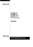
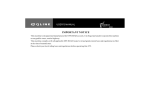
INSTRUMENT PANEL
% S H I F T INDICATOR
LIGHT
RIGHT TURN INDICATOR LIGHT
FIGENERATOR
LIGHT
SEAT BELT REMINDER
LIGHT
SERVICE ENGINE SOON
REMINDER LIGHT
4
3 -TACHOMETER
.
O I L PRESSURE GAGE
4
- W ' t 5 r
0
OIL PRESSUREGAGE
VOLTMETER
SECTION
2C
INSTRUMENT PANEL
r If you judge it to be safe, drive
BRAKE SYSTEM WARNING
LIGHT
The regular braking system is a split system
designed so that one part will provide some
braking if there is a loss of hydraulic pressure
in the other part of the system. The system has
a red "BRAKE warning light located in the
instrument panel speedometer cluster.
As a bulb check, the "BRAKE light should
come on briefly during engine starting. To
serve as a reminder, the light should stay on
when the parking brake is not fully released
and the ignition is on. Have the system repaired
if the light does not come on when it should.
This warning light does not do away with the
need for brake inspection and maintenance.
The brake fluid level must be checked
regularly. See your Maintenance Schedule
booklet for other brake checks.
If the light remains on after engine start up or
comes on during operation of the vehicle, it
may mean that there is something wron,g with
pan of the brake system.
What to do:
1. Pull off the road and s t o ~carefullv.
Remember that:
. r Stopping distances may be longer.
(See "Consumer Information, Vehicle
Stopping Distance" in the "Specifications" section of this manual.)
r You may have to push harder on the
,.
pedal.
0 The pedal may g o i o w n farther than
normal.
t.
2. Tryoutthe brakes by starthgand stopping
on the road shoulder - then:
--
cautiously at a safe speed to the
nearest dealer for repair. Or,
a Have car towed to the nearest dealer
for repair.
Continued driving without necessary repairs
could be dangerous.
"ENGINE COOLANT
TEMPERATURE LIGHT
pi
This light is located in the instrument panel cluster and should
come on to warn the driver that
.
H
N
the engine coolant has overheated and immediate action is
required to correct the condition. As a check
that the bulb and its circuit are working, the
light will come on during engine starting. If the
light does not come on during this check, have
it repaired promptly. If the light comes on at any
other time, see "Engine Cooling System Overheating" in Section 3.
--
-
CAUTION: If the Engine Coolant Tempera.
ture Light or Gage shows an overheat
. or-you-have-other-reason-to
cond~t~on
suspect the engine may be overheating.
continued operation of the engine (other
than as explained in Section 31 even for a
short time may result in a fire and the risk
of personal injury and severe vehicle
damage. Take immediate action as
outlined under "Engine Cooling System
Overheating" in Section 3.
.--
<
.
INSTRUMENT PANEL
2C-3
GENERATOR LIGHT
1
-
The light will go on when the
ignition key is in the "Run"
position, but before the engine
1s started. After the ensine
starts, the light should go-out
and remain outwhen the engine speed is above
idle. If the light remains on when engine is
running above idle speed, have your Pontiac
dealer locate and correct the trouble as soon as
possible.
"SERVICE ENGINE SOON"
LIGHT
Cars with the Computer Command Control
system inc1ude.a "SERVICE ENGINE SOON"
light on the instrument panel,.designed to
indicate the need for system service. It will
come on during engine starting to let you know
the bulb is working. (The light will stay on a
short time after the engine starts.) Have the
system repaired if the "SERVICE ENGINE
SOON light does not come on during'engine"
starting. If the light comes on, either intermittently or continuously while driving, service to
the Computer Command Control system is
'required. Although in most cases the car is
drivable, and does not require towing, see your
Pontiac dealer as soon as possible for service.
-?
Continued driving without having the
Computer Command Control system Serviced
could cause damage to the emission control
system. It could also affect fuel economy and
.drivability.
.
AJAR LIGHT
The "AJAR" light is designed to come on any
time the front compartment lid, the rear
compartment lid, or either door is not fully
closed. The "AJAR" light is located in the
instrument cluster to the left of the engine
temperature gage.
HEADLIGHT SWITCH
The headlight switch controls
Most cars sold in the United States (and some
cars sold in Canada) have the Computer
Command Control system.
.
See also "The Computer Command Control
System'' in Section 5.
.
01
-
the
sidemarker
headlights,
lights,
parking
taillights,
and
interior lights, and the instrument panel lights.
Press in the upper left portion of the switch to
open the headlight assemblies and turn the
headlights on. Press in the upper right portion
of the switch to light the parking lights. (The
parking lights come on automatically when the
headlights are turned on.)
With either the headlights or the parking lights
on, illumination of instrument panel controls.
gages, speedometer cluster, etc. is provided.
The dial (thumbwheel), located below the
headlight switch, controls the brightness of the
instrument panel illumination. Rotating the dial
downward will dim the I.P. lights, rotating the
dial upward will brighten them, and rotating the
dial to the full "up" position will turn on the
dome and courtesy lights.
The headlight assembjies are designed to open
when the headlights are on and close when the
headlights are turned off. The headlight assemblies can be opened without turning on the
1
INSTRUMENT PANEL
2C-4
CAUTION: To help prevent personal injury
and vehicle damage, follow these steps:
1. Turn off the headlights.
2. Open thehood.
3. Disconnect the single blue wire at the
headlights by turning on the parking lights and
lightly pressing in the headlight switch.
.
'
black plastic in-line connector located on
the inboard lower side of each inoperative
headlight.
, ,
'4. For each inoperative headlight, rotate the
The headlight doors should be open whendoor-motor's-manual-control.knob.in.the-driving in iceor snow, and when washing the
direction of the arrow on top of the knob
car. (Before entering an automatic car wash.
- toward "Open." Continue turning the
make sure open headlights will not be
knob until an increase in effort is felt (a'
damaged by the equipment.)
"click may be heard).
Emergency M a n u a l Headlight
Oneration
In emergencies, each headlight may be opened
manually; do not force the doors or use other
methods.
5. Close the hood and turn on the lights to
make sure both headlights come on, and
the doors are all the way up.
6. Leave the inoperative door(s) open and do
not &connect the blue wire until repair is
made.
-
'
'.
.
.
_.a
INSTRUMENT PANEL
The speedometer hand indicates car speed in
miles per hour and kilometers per hour.
The trip odometer can be reset to zero by
pushing in the knob, located below the speedometer face.
THIS SHOULD BE DONE ONLY WHEN THE
VEHICLE IS STOPPED.
ODOMETER
FUEL GAGE
SPEEDOMETER
The odometer is above the speedometer face.
Total accumulated mileage is given in miles
(kilometers on Canadian cars).
TAMPER-RESISTANT ODOMETER
Federal law prohibits tampering with car
odometers to alter accumulated mileage. For
your protection the odometer of this car is
designed with tamper-resistant features to
indicate tampering. If silver lines appear vertically between odometer numerals, it is likely
that the odometer has been turned back or
reversed. The mileage shown may not be
actual.
Whenever a new.odometer is installed and
cannot be set to the same mileage registered
on the prior odometer, the law requires the
owner to install a label on the driver's door
frame to show the previous odometer reading
. and the date of replacement. The replacement
odometer must then be set to zero: To:
. ; determine the actual car mileage, add the
. . ' mileage shown on the label to the current
:1.
odometer reading. If the replacement
:. . odometer can be settothe same mileage as the
prior odometer, no door frame label is needed.
'
TRIP ODOMETER
.I
The trip odometer is to record mileage on trips
or during extended driving.
The fuel gage, in operation only
when the ignition is on,
indicates the quantity of fuel
remaining in the tank. The far
left markbn the gage indicates
~ m p &(E), while the far right indicates Full (F).
The needle does not return to empty with the
ignition OFF.
Some normal variations in reading will occur,
as noted below
r Needle does not move from Full (F) until
substantial distance has been driven.
r Needle moves when braking, accelerating,
or making turns. This is caused by fuel
movement in the fuel tank.
1
r Needle occasionally indicates less than
..
. Full (F) after fuel tank is filled. This will
occur if the car is not level when filled, or
. . if the automatic pump nozzle shuts off too
.. soon.
-
.
ENGINE COOLANT : ..
TEMPERATURE GAGE
"
....
;
.. .
This gage is located on the instrumental panel'
to the right of the speedometer. If the gage
shows that an overheat condition exists - as
indicated by the gage pointer approaching the
250' mark - immediate action by the driver is
required. If an overheat condition is shown, see
"Engine Cooling System Overheating" in
I N S T R U M E N T PANEL
2C-6
Section 3. The coolant temperature indication
will vary with air temperature and operating
conditions. The ignition must be on for
accurate readings. Prolonged driving or idling
in very hot weather may cause the pointer.to
move beyond the center of the gage. Make a
practice of scanning this and other gages while
driving, especially in hot weather and/or when
the vehicle is under load. See Caution under
"Engine Coolant Temperature Light."
tachometer. The tachometer may not return to
zero when the ignition is turned off.
CIGAR LIGHTER
To operate the cigar lighter on
the console depress the lighter
and i t will automatically heat
and snap out, ready to use.
Avoid holding the lighter in by
hand while it is heating as damage to the
heating element may result.
OIL PRESSURE GAGE
,
See "Console Controls" in Section 2D
Under normal engine operating
conditions, the oil pressure
should be 20 t o 60 psi. Should
the pressure fall below this
range (other than at idle)
immediately turn the engine off and investigate
the cause. Slight fluctuations in oil pressure
gage readings may occur; this is normal.
Engine oil pressure should not fall below 4 psi,
even at idle. Pressures are always higher when
the oil is cold.
ASHTRAY
The ashtray may be simply pulled out for
cleaning (see "Console Controls" in Section
24:
0
Open either access door on the console.
Remove either ashtray for cleaning by
lifting the ashtray straight up.
VOLTMETER (V6 ENGINE)
Slide the ashtray back into the bracket
after cleaning.
The voltmeter has the advantage of providing
a warning of impending banery problems.
ye
ELECTRIC REAR
-1fthe-meter-reads.below-l-l-volts.or.abo~e~~6~~
volts continuously, it indicates charging system r
OMPAWTMENT-LID-RELEASE,
DroblemS rewiring immediate attention. it is
(OPTIONAL)
normal for thk meter to read between 11 and
An electric rear compartment
13 volts during periods of extended idle or just
lid release switch is provided
after starting.
which errn nits o ~ e n i n athe rear
]
compakment lid'from k i d e the
TACHOMETER
car by pushing the release
The engine tachometer indicatewngine speed
button located on the instrument panel. The
in revolutions per minute (RPM). The engine
release bunon is operational whenever the car
should not be operated in the red area of the
baneryh connected, and the ignition is on.
,
I
;.
'.'
INSTRUMENT PANEL
ELECTRIC REAR WINDOW
DEFOGGER (OPTIONAL)
~
The electric rear window
defogger consists of a heating
element bonded to the inside
surface of the rear glass. The
unit is operated by a switch on
the right side of the instrument panel and
functions only i n the ON position. A small light
in the control switch illuminates whenever the
h%Xted rear window is operating. The heated
rear window will not feel warm to the touch.
After the defogger has operated for 5 to 10
minutes, the system will automatically shut off.
If further defrosting is desired, simply turn the
switch on again.
VENTILATION SYSTEM
Your Fiero has a flow through ventilation
system that provides a supply of outside "ram"
air into the carwhen it is moving. When the car
is not in motion you can get a steady flow of
outside air into the car with the heater or air
conditioning blower iunning.
With the side windows closed, the flow through
ventilation system provides outside air flow
into the front air inlet grilles, through the car
and out the rear air exhaust valves. (See illustration.)
Operating Tips
r lea; snow and ice from the hood and air
inlet in front of the windshield. Thishelps
the heater and defroster work better and
reduces the chance of fogging the inside
of the windshield.
r Run the blower on "HI" for a few moments
before driving off. This helps clear the
intake ducts of snow and moisture and
reduces the chance of fogging the inside
of the windows.
r Always keep the front inlet grilles clear of
obstructions (leaves, ice, snow, etc.).
The following pages of this manual provide
more operating tips for getting maximum
heating and cooling comfort. Also see "Engine
Exhaust Gascaution (Carbon Monoxideratthe
beginning of "Starting and Operating," Section
2 ofdhis manual.
INSTRUMENT PANEL
HEATER OPERATION
(Models W i t h o u t A i r Conditioning)
A i r Control Lever
The air control (upper) lever regulates the air
flow from the heater and defroster outlets as
well as the upper vents in the instrument panel.
VENT
Air flow from the upper vents in the center
and each side of the instrument panel.
HEATER
Maximum air flow to the heater outlet and
side window defoggers with a slight
amount to the windshield.
Fan Control Knob
The fan control knob (OFF HI)
provides speed control of the
fan. The fan will operate any
time the ignition is turned to
RUN, unless the fan switch is
placed in the OFF position.
-
t
CUSTOM AIR CONDITIONING
The air conditioning system offers year-round
comfort, for all seasons and climates, day or
night, in rain or in brilliant sunshine. Combining
the heater and air conditioner into an intb
grated package ~ i v e syou complete comfort
regardless of the weather.
REGULATING YOUR AIR
CONDITIONING SYSTEM
For normal, average conditions:
r WINTER-Select either BI-LEVEL, VENT or
DEFROST
HEATER positions.
SUMMER-Select MAX. NORM, BI-LEVEL
Maximum air flow to the windor VENT positions.
shield. and side window
.
ALL SEASONS-Regulate the car temperadef<gge with some air. flow
ture
by
moving
the
COLDHOT
lever.
frotkthe heater outlet.
..,.,
v
:...?L, ,:.
During some A/C operation conditions, slight
":
<
, .
. .. .
in'creases and decreases of engine s~eed/
power ,may be noticed. This charact'eristic
.j ,
Temperature:Control-Lever
. ,
- _a. . _should
_
be considered:normal;~as~the-system-is-1-The temperature control 'iever (COLD -. HOT). 'ddsigned to cycle the compressor ON and OFF . '..
' t
regulates the temperathe of the.air'discharged
to maintain desired cooling. The reduced.
from the upper vent, heater, side window
compressor operation should benefit' fuel
.
defoggers and defroster outlets. '
.: economy.
%
.
.
-
INSTRUMENT PANEL
2C-9
INSTRUMENT PANEL
2C-10
Push B u t t o n Controls
The push bunon controls regulate air flow from
the heater, side window defogger, defroster
and adjustable A/C outlets. It also controls
operation of the refrigeration compressor.
a OFF-Limited air flow from defroster and
heater outlets (see FAN CONTROL KNOB).
a MAX-An air conditioning position where
passenger compartment air is blended
with a small amount of outside air, conditioned and then distributed through the
adjustable instrument panel air outlets. In
MAX the system will provide maximum
cooling and variable fan speed. Useful in
conditions of very high temperature and
humidity.
Provides a slight gain in fuel economy
compared to "Norm" position. The blower
motor noise level will be higher in "Max"
than in "Norm" for a given fan speed.
a NORM-An air conditioning position where
outside, conditioned air is" directed
through tlie adjustable instrument panel
air outlets. Used in most air conditioning'
situations.
through the heater and adjustabie instrument panel air outlets, with some air flow,
through the defroster and side.window
outlets to the windshield .and side
windows. This position gives cool upper
level air and warm heater air when the
temperature lever control is in the middle
40 percent of the .temperature control
range. (Useful in cool weather and bright
sun conditions.)
a VENT-Outside air is directed through the
adjustable instrument panel air outlets.
Used in cool-to-moderate weather where
refrigeration is not required. This is a fuel
economy position, with the refrigeration
system compressor turned off.
a HEATER-Outside air is directed through
the heater outlet and side window
defoggers, with a small amount to the
windshield. Another economy position.
a DEFROST-When the outside air tempera-
ture isaboveapproximately 4'C(40'F), the
compressor will operate to provide
outside, conditioned (dry) air to the windshield, with a small amount from the
heater air outlet and side window
defoggers. Used in fogging and icing
situations.
1 Temperature Control Lever
'
The temperature control lever regulates the
temperature of the air entering the passenger
compartment. Position of the lever determines
air temperature in any of the operating
Fen Control K n o b
The fan control knob (LO HI)
provides speed control of the
blower fan in all Push Bunon
Control positions except OFF.
Note: When the Push Button
Control is in OFF, the fan will not operate; the
movement of the car, however, may provide
-some ait flow.
-
I .
INSTRUMENT PANEL
For proper operation of the air conditioning
system, car windows should always be closed
except for the first two or'three minutes to
remove hot air if the car has been closed. This
provides a fast cool-down.
DELCO SOUND SYSTEMS
your car may have one of several optjonal
Delco GM Sound Systems. (To listen to any
system, the ignition must be in "Run" or
"Accessory.")
NOTICE: All Delco sound systems have
ungrounded speakers. Installing add-on
tape players, CBs or other units which use
the car speakers may damage your Delco
sound system. Please consult your dealer
in advance if you are considering
FM Stereo
FM broadcasts are "line of sight'' from station
antenna to receiving antenna. The range is
often limited to 25 miles (40 km) or less for
steady reception. Tall buildings or hills may
cause fluner or noise which is not the fault of
the radio; select a stronger station for clear
sound.
A M Stereo
AM stations broadcasting C-OUAMO' stereo
may be received in stereo if the.recek,er has
this feature. Switching to stereo improves
fidelity, but may increase noise on weaker
stations. Switchmg stereo "off" may improve
the reception in this case.
C-QUAMO is a registered trademark
of Motorola, Inc.
Stereo Indicator
An indicator lights whenever
broadcast is being received.
a stereo
A M M o n a u r a l Radio
.
The, following contrdr&a!e on AM monaural
sound systems:
:.
~eft'~nob
This'knob turns theset on oroff,
and controls the volume.
Behind the volume knob is a
1, .
tone control. When turned to
the right, it increases.treble and
'voicL-clarity; when turned to the left, it
increa.ses bass.
a RightKnob
.
.
I ....,., I This knob is a manual tuning
control for khoosing radio
stations. For radios with rear
I ' I speakers, a fader control is
behind it. This control adjusts
.
INSTRUMENT PANEL
I
2C-12
the sound between the front and rear speakers.
r Push Bunons
Each radio has five push buttons you can
use to select your favorite stations easily.
After using a push button, you may have to
"fine-tune" the radio by hand for the best
reception.
To "Set Up" the Push Buttons:
1. Use the tuning knob to tune in the
desired station.'
2. Choose the button you wish to use
and pull it straight out.
3. Push in the button until it stops. The
radio is designed to tune to the
selected station whenever you push
the button.
Balance Control (located behind upper
knob) - turn to adjust lefthight speaker
balance.
D
r Lower Knob - rotate knob to tune radio
stations manually. Frequency will be
displayed during tuning. Press knob to
select AM or FM band alternately.
a FrontIRear Speaker Control (located
behind lower knob) - rotate control to
adjust the sound between the front and
rear speakers.
-
Bass and Treble Controls slide treble
control up to increase treble, or down to
decrease treble. Slide bass control up to
increase bass, or down to decrease bass.
r Pushbunons
The radio has four pushbuttons you can
use to select your favorite stations easily.
You may select four AM and four FM
stations for a total of eight selections.
To Set Pushbuttons:
.
ETR A M - F M S t i r e o (Seek/Scan)
Clock -.
~.
with''
_-.
To Operate the ETR AM-FM stereo.R$Jio:
r Power Button ("PWR") - prC;& td turn
radio on. Press aaain
to turn'rgdio irk
"
.
I)
^
+
r Upper Knob - rotate knob i o control
volume. Press knob to recall station
freauencv
.
, when listenina to the radio with
ignition on or to displa; time-ofday with
ignition off.
~
~~
.
3.
.
a .
=
1. Make sure the bandswitch is on the
band you want. Then, tune in the
desired station.
2.
Press SET button. The SET indicator
,
'
'
light on the dial will light up. Then
.
.- press one of the four station pushbut,
tons, The SET indicator light will then
.<
go out.
2 '
!
The radio will then tune to the
selected station whenever you press
the station button.
' Seek and Scan
Use the SEEK and SCAN buttons for
' automatic station tuning.
.-
.
\
I:
L
L
A
INSTRUMENT PANEL
.
Press SCAN button to sample each station
being received automatically. To stop
SCAN, press SCAN'button again.
The SCAN indicator light on the frequency
dial will be lit during SCAN operation.
Press the SEEK button to locate and retain
the next listenable 'station on the band
automatically.
The FM stereo indicator will light when
tuned to an FM station broadcasting in
stereo. Stereo (dual channel) sound is
more realistic.
Time Set
To set hour, press SET button. The SET
indicator light on the dial will then light up
and the radio frequency will be displayed:
Then press the SCAN button, holding
SCAN button in until correct hour appears.
'>
To set minutes, press SET button. The SET
indicator light will then light up and the
radio frequency will be displayed. Then
press SEEK button, holding SEEK button in
until correct minute appears.
NOTE: After you press the SET button, the
radio frequency will be displayed. The
time-of-day will be displayed when y~,y.
r
press the SCAN or SEEK button.
2C-13
ETR AM-FM Stereo (Seek/Scen) with
Clock a n d Cassette
To Operate the ETR AM.FM Stereo Radio:
r Power Button ("PWR") - press to turn
radio on. Press again to turn radio off.
r Upper Knob - rotate knob to control
volume. Press .knob to recall station
frequency when listening to the radio with
the ignition on, or to display time-of-day
with ignition off. Press knob to select the
other side of the tape when the cassette is
playing.
r Balance Control (located behind upper
knob) - turn to adjust lefthight speaker
balance.
r Lower Knob - rotate knob to tune radio
stations manually. Frequency will be
displayed during tuning. Press knob to
select AM.or FM band alternately.
r FronVReer Speaker Control (located
behind lower knob) rotate control to
adjust the sound between the front and
rear speakers.
. .
r :.Bass and Treble ~ o r i t ~ o-l sslide treble
r ~ c o n t r oup
l to increa?Qreble, or down to
'decrease treble. Slide bass control up to
increase bass, or down to decrease
bass.
. . .' .. , . , . ..
r Pushbunons
.. .
~i$
!adl;o has four pushbuttons you can
.use to.select your favorite stations easily.
You m a y select four AM and four FM
statioris for a total of eight selections.
To Set Pushbuttons:
1. Make sure the bandswitch is on the
band you want.':Then, tune in the
desired station. ! .
.
-
'
INSTRUMENT PANEL
2. Press SET button. The SET indicator
light on the dial will light up. Then
press one of the four station pushbuttons. The SET indicator light will go
out.
The radio will then tune to the
selected station whenever you push
the station bunon.
r Seek and Scan
Use the SEEK and SCAN buttons for
automatic station tuning.
Press SCAN bunon to sample each station
being received automatically. TO stop
SCAN, press SCAN bunon again.
The SCAN indicator light on the frequency
dial will be lit during SCAN operation.
Press the SEEK bunon to locate and retain
the next listenable station on the band
automatically.
The FM stereo indicator will light when
tuned to an FM station broadcasting in
stereo. Stereo (dual channel) sound is
more'realistic.
..
Time Set:
To set hour, press SET button. The SET
indicator light onthe dial will then light up
-and.the radio frequency will be displayed.
Then press SCAN button, holding SCAN
bunon in until the correct hour appears. .
. To set minutes. oress SET button. The SET
indicator light'hill then light up.and the
radio frequency will be displayed. Then
press SEEK button, holding SEEK bunon in
until correct minute appears.
NOTE: After you press the SET button, the
radio frequency will be displayed. The
2C-14
time-of-day will be displayed when you
press the SCAN or SEEK bunon.
To Operate Tape Player:
Insert the cassette squarely through the
door. This automatically switches the unit
from radio to tape operation. If the sound
is garbled (or there is no sound), eject the
tape and reinsert it squarely.
After the cassene has snapped into
position, adjust the volume and fader
controls to your preference.
A
To advance to the next selection quickly.
press the button next to the lighted
indicator. To listen to an earlier selection,
press the bunon next to the unlighted
indicator. To stop the forward or reverse
movement, press the STOP-EJECT button;
press again to eject the tape.
Reversing Sides - Press the upper left
knob (volume knob) to play the other side
of tape. When end of tape is reached,' it
automatically reverses direction and pliiy's
'I :,.
other side.
>+,:.
,.
Tape Indicator Lights - When lighte'd.T:i$
arrow located below tape door point<.!&.$
'Ieft:'the top side of tape is being
when arrow points "right," bonom side$ ,:$&,;
.
- . a
:., : '3.
being played.
...
To remove the tape or listen to the r a d i q
push the STOP-EJECT bunon.
I4
~~
I
.
Press the Dynamic Noise Reduction,
(DNRTM) bunon to remove high frequency
background hiss on AM, FM. FM stereo;
. .
and tape.
For best results, 120 minute tapes are'not
recommended.
s
.
INSTRUMENT PANEL
2C-15
rear speakers.
r AM Stereo ("AM-ST") - press to receive
;
ETR A M Stereo-FM Stereo lSeek/Scan)
with Auto-Reverse with M u s i c Search
Cassette 5-Band Equalizer a n d Clock
To operate the ETR AM S t e r e ~ F MStereo
radio:
Power Button ("PWR") - press t o turn
radio on. Press again to turn radio off.
r Upper Knob - rotate knob to control
volume. Press knob to recall station
frequency when listening to the radio with
;. the. ignition on, or to display timeofday
:?..with ignition off. Press knob to select the
.,?@other side of the tape when the cassette is
.
-
,,Loudness Bunon ("LOUD")
Press to
ss frequencies when the radio is
'Balance control (located behind ripper
leftlright
. speaker
.
.
.<.~.
2%. .:,
. . balance.
., .
.,:
.
Lower Knob - rotate knob to tune radio
, , . .r'.
.:.-'!. .I stations manually. Frequency will be
'.i.. .+. displayed during tuning. Press knob to
....
:. : alternately select AM or FM band.
0 . FronVRear Speaker Control (located
;. behind lower knob) - rotate control to
'. adjust the sound between the front and
.!i
.
AM stereo. " Stereo" indicator light will be
displayed when tuned to a station broadcasting C-QUAMO' AM stereo, provided it
is being received with adequate signal
strength in your locality. When the bunon
is"out," all AM stations will be received in
mono.
C-QUAMO is a registered trademark
of Motorola. Inc.
0 FM Stereo - the stereo indicator will light
when tuned to an FM station broadcasting
in stereo. Stereo (dual channel) sound is
more realistic.
"Stereo" operation means the radio is
separating a stereo broadcast back into
the original two channels, called "left" and
"right." Stereo sound is noticeably
realistic to the ear.
r 5-Band Graphic Equalizer allows you to
adjust bass, midrange, and treble to suit
personal taste. Move control up to
increase frequency range, or down to
decrease frequency range.
NOTE: 60 and 250 .denote bass; 1K
denotes midrange; 3.5K and 10K denote
treble.
Generally, the l k control is placed in the
' center(detent) position, while the bass and
treble controls are adjusted upward to
varying degrees.
Siiice the 10K control has the most
influence on treble, it may produce high
frequency hiss when fully up. If this
occurs, move it down until the hiss disapp
ears. '
-
..
INSTRUMENT PANEL
2C-16
bunon in until correct hour appears.
This radio has automatic Dynamic Noise
Reduction (DNRTM) to "reduce" high
To set minutes, press SET button. The SET
frequency background hiss on AM, FM,
indicator light will then light up. Then
AM Stereo, FM Stereo, and tape.
press SEEK bunon, holding SEEK bunon in
Pushbunons
until correct minute appears.
The radio has four pushbuttons you can
NOTE: After you press the SET button, the
use to easily select your favorite stations.
radio frequency will be displayed. The
You may select four AM and four FM
timeofday will be displayed when you
stations for a total of eight selections.
press the SCAN or SEEK bunon.
To Set Pushbunons:
To Operate Tape Player:
1. Make sure the bandswitch is on the
Insert the cassette squarely through the
band vou want. Then. tune in the
door. This automatically switches the unit
desirei station.
from radio to tape operation. If the sound
2. Press SET bunon. The SET indicator
is garbled (or there is no sound), eject the
light on the dial will light up. Then
tape
and reinsert it squarely.
press one of the four station pushbuttons. The SET indicator light will go
After the cassette has snapped into
out.
position, adjust the volume and fader
controls to your preference.
The radio will then tune to the
selected station whenever you press
To advance the tape, press the forward
the station bunon.
("FWD")
bunon. To listen to the earlier
Seek and Scan
portion of the tape, press the reverse
("REV")bunon. To stop forward or reverse
Use the SEEK and SCAN buttons for
movement, press the opposite bunon
automatic station tuning.
lightly.
Press SCAN button to sample each station
being received automatically. To ,stop
To listen to the next selection, slide the
SCAN,.press SCAN bunon again. .. . ~. . "SEARCH" button to the right and press
the fornard (''MID) button. The radio will
The SCAN indgator light on the frequency .
.
dial will be 1it)during SCAN operaFon.
,.' - seek the next selection.
To listen to the previous selection again,
Press the SEEK button to locate and:retai%
the next listenable station on thg ,band 9. .. slide the "SEARCH" bunon tothe right and
,
x
press the reverse ("REV") button. The radio
automatically.
L: :f will
repeat the previous selection.
Time Set:
The;'OnV light, to the right of the search
To set hour, press SET button. The SET
switch, will be on while the search
indicator light on the dial will then light up.
function is engaged.
Then press SCAN bunon, holding' SCAN
~
.
.
~
.
,
INSTRUMENT PANEL
\
/
1
2C-17
When the left triangle indicator light is lit.
the top side of the tape is playing. When
the right triangle indicator light is lit, the
bonom side of the tape is playing.
To play the other side of the tape before
the present side has ended, press the
upper left knob. This will automatically
play the opposite side of the tape.
NOTE: When end-of-tape is reached in one
direction, the unit will automat]cally play
the other side of the tape. To remove the
tape or listen to the radio, push the EJECT
bunon.
When the ignition is turned off, the tape is
automatically ejected.
Select the setting for proper tape equalization (CrG) as follows:
1. Select 70 usec (push bunon in).
2. Select 120 usec (bunon is out).
The equalization setting which is desired
will vary according to the type of tape
being used. Chrome and metal tapes
usually have 70 usec equalization, while
standard (iron)tapes have 120 usec equal.
ization.
The tape bias is often indicated on the
cassette label or case.
For best results, 120 minute tapes are not
recommended.
r Power Bunon ("PWR) - Press to turn
radio on. Press again to turn radio off.
r Program Recall Bunon ("PRG-RCL") Press to recall station frequency when
listening to the radio with the ignition on,
or to display the time-ofday with ignition
off. When the cassette is playing, press to
play other side of tape..
AM.FM Bend Switch Bunon ("AM-FM'Jpress bunon to alternately select AM or
FM band.
Volume Bunons YO^) - press and hold
bunon having arrow pointing
up (4to
5
increase volume.
~resb.'and hold bunon having arrow
pointing down
to decrease volume.
Press and hold both buttons at the same
'time to return to the p!eset volume level.
NOTE: If radio is playing at high volume
and the radio or the ignition is turned off.
the radio will return t o the preset volume
level.
AM Stereo Bunon ("AM-ST") press to
ETR (Touch Control) A M Stereo-FM
receive AM stereo. Stereo indicator light
Stereo (SeeWScan) e n d Auto-Reverse
on the dial will bedisplayed when tuned to
Cassette with 5-Band Equalizer and Clock
a station broadcasting C-QUAMO' AM
-.
F
stereo, provided it is being received with
To Operate the Radio:
adequate signal strength in yourlocality.
.
(n
-
I
,
INSTRUMENT PANEL
a
a
r
a
.
2C-18
To set minutes, press SET button. The SET
When the button is "out." all AM stations
indicator on the dial will light. Then press
will be received in mono.
SEEK button and hold until correct
C-QUAMO is a registered trademark
minutes appear.
of Motorola, Inc.
a Balance Bunons ("BAL) - Press and hold
FM Stereo - the stereo indicator will light
BAL button with arrow pointing to the left
when tuned to an FM station broadcasting
(4)to adjust sound to the left. Press and
in stereo. Stereo (dual channel) sound is
hold button with arrow pointing to the
more realistic.
right (b)to adjust sound to the right.
Loudness Bunon ("LOUD)
press to
Hold both BAL buttons at the same time to
boost bass frequencies when the radio is
return balance control to its center
olavino
-, " at low volume.
position.
Tune Bunons ('TUNE)
N0TE:Above the balance buttonsisa light
Press and hold button having arrow
indicating the balance level.
pointing up (A)to tune up the frequency
Fade Bunons ("FADE) - Press and hold
band manually.
button with arrow pointing up (4to fade
Press and hold button having arrow
sound to the front of the car. Press and
pointing down (r)to tune down the
hold button with arrow pointing down (V)
frequency band manually.
to fade sound to the rear of the car.
When tunlng either up or down the
Hold both fader buttons at the same time
frequency band, pressing the other button
to return fader to its preset center position.
at the same time increases the scanning
NOTE: To the left of the fade buttons is a
rate.
light
indicating the fade level.
Seek and Scan Bunons
PuShbunons
Press SCAN button to sample each station
The
radio has four pushbuttons you can
being received automatically. To stop
use to select your favorite stations easily.
SCAN, press S A N b u t t o n a second time.
- You can select-four- AM and four FM
The SCAN indicator will b e l i i l p during
stations for a total of eight selections.
SCAN operation.
To set pushbuttons:
Press SEEK button to locate and retain the :
next listenable station on the band auto1, ~~k~ sure the band switch is on the
matically.
band you want. Then, tune in the
n
Time Set:
desired station.
2. Press SET button. The SET indicator
To set hour, press SET button. The SET
light on the dial will be displayed.
indicator on the dial will light. Then press
Then press one of the four station
SCAN button and hold until correct hour
pushbuttons. The SET indicator light
appears.
,f
will go out.
-
'
+
'
I
I
r
'
.
2C-I 9
INSTRUMENT PANEL
h
i
'.
%
3
portion of the tape, press the' reverse
("REV")
button. To stop forward or reverse
The radio will then tune to the selected
movement, press the opposite button
station whenever you push that station
lightly.
button.
To listen to the next selection, elide the
5.Band.Graphic Equalizer - allows you to
"SEARCH" button to the right and press
adjust bass, midrange and treble to suit
the forward ("FWD"J button. The radio will
personal taste. Move control up to
seek
the next selection.
increase frequency range, or down to
To listen to the previous selection again,
decrease frequency range.
slide the "SEARCH" button tothe right and
NOTE: 60 and 250 denote bass; 1K
press the reverse ("REV) bunon. The radio
denotes midrange, 3.5K and 10K denotes
will
repeat the previous selection.
treble.
The
''On" light, to the right of the search
Generally, the 1K control is placed in the
switch,
will be lit while the search function
center idetent) position, while the bass and
is
engaged.
treble controls are adjusted upward to
When the left triangle indicator light is lit,
varying degrees.
the top side of the tape is playing. When
Since the 10K control has the most
the
right triangle indicator light is lit, the
influence on treble, it may produce high
bottom side of the tape is playing.
frequency hiss when .fully up. If this
To play the other side of the tape before
occurs, move it down until the hiss disappthe present side has ended, press the
ears.
"PRG-RCL"
button. This will automatically
This radio has automatic Dynamic Noise
play
the
opposite
side of the tape.
Reduction (DNRTM) to remove high
NOTE: When end.of-tape is reached in one
frequency background hiss on AM, FM.
direction, the unit will automatically play
AM stereo, FM stereo, and tape.
the other side of the tape. To remove the
To Operate Tape Player:
tape or listen to the.i&o, push the EJECT
Insert the cassette squarely through the
button.
door. This automatically switches the unit .:
When the ignition is turned
off, ihe tape
from radio to tape operation. If the sound .' >. automatically ejected. ,
is garbled (or there is no sound), eject the
Select the setting for proper tape equalizatape and reinsert it squarely.
. ,>
tion (CROI) as follows:
After the cassette has snapped into
1. Select 70 usec (push buttin in).
position, adjust the volume and fader
controls to your preference.
2. Select 120 usec (button is out).
The eaualization set tin^ which is desired
To advance the tape, press the forward
rWD) button. To listen to the earlier
will vary according t i t h e type of tape
t
'
,v
k
INSTRUMENT PANEL
being used. Chrome and metal tapes
ususlly have 70 usec equalization, while
standard (iron)tapes have 120 usec equalization.
The tape bias is often indicated on the
cassette label or case.
For best results, 120 minute tapes are not
recommended.
Tape and Tape Player Care
Optimum performance can be maintained by
cleaning the internal tape head, capstan, and
pinch roller periodically (approximately each
100 hours of operation). This can be done by
inserting a nonabrasive cleaning cassette in
place of the music tape.
store cassettes away from extreme heat or
direct sunlight. protect the open ends from dirt
or damage; store them in their original cases or
other protective cases.
For best results. 120 minute tapes are not
recommended.
When leaving the car, cassettes may be left in
the tape player if the deck is theyauto reverse"
type (tapes are either automatically ejected or
internally protected). In other models, tapes
2C-20
should be removedto prevent possible damage
to the tape or tape player.
MOBILE RADIO SYSTEMS
Mobile tweway radio units and mobile
telephone equipment are subject to federal
rules and must be installed by trained
personnel. Certain such equipment or the
manner of its installation may possibly
adversely affect car operation. Expenses
incurred to protect the car's systems from the
interaction with added mobile communication
systems are not the responsibility of Pontiac.
Citizen Band (CB) radios and garage door
openers normally will not affect car operation.
ANTENNA
~
i M~~~
~ A~~~~~~
~
d
The fixed mast antenna is designed to
withstand most car washes without damage. It
cannot
uo or
the. mast
.- - .be
~adiusted
.,
--- ~
-..
- -down.
becomes sliahtlv bent. vou can straiahten it bv
hand. The masi antenna can be ;placed ii
severely bent (by vandalism, etc.). Mast
antennas must be kept clean for good performance.
-r
~
OTHER CONTROLS
AND FEATURES
.
?\
a
.J'
CONSOLE CONTROLS
The console assembly, between the front seats,
attaches to the instrument panel and provides
easy access by the driver to many controls:
r Ashtray and Cigar Lighter - See Section
2C.
Automatic Transaxle Shift Lever - See
Section 2.
Manual Transaxle Shifterand Shift Pattern
See Section 2.
r Power Window Switches - See Section 1.
r Power Sport Mirror Control See Section
1.
Console Compartment Storage Box (Glove
Box).
-
-
REMOVABLE SUNROOF
.
.
c
The Fiero Removable Sunroof is a hinged glass
panel. The panel can be opened by moving the
latch release handle forward and up to lock the
glass in place. The glass will stay open only in
one position when the rear of the glass is
raised about 40 millimeters (1-1/2 inches).
-
The glass panel can also be removed
completely. First, open the Removable Sunroof <;
as described.Then, press the glass release tabs'
on either side of the release handle and lift thf.
panel up and outto disengage the front hinges:--"
The air deflector, which is stored in the front
compartment, may then be put in place by
sliding the deflector tabs into the roof slots and
pushing downward to secure in place. Store
the glass panel in the front compartment area
.
@MANUAL
TRANSAXLE
.. ,
@-AUTOMATIC
TRANSAXLE
A-PRESS BUTTON TO SHIFT
TO REVERSE OR PARK
3 'POWER SPORT MIRROR
.
0.CONTROL
@POWER
@-ASH
@-GLOVE
WINDOW SWITCHES
TRAYlLlGHTER
BOX
OTHER CONTROLS AND FEATURES
with the front hinges secured under the
forward support pads. The deflector is stored
beneath the glass panel with the leading edge
of the deflector down and deflector retainer
tabs outboard of the slots in the support.
To install the glass panel, hold it at a 60 degree
angle as shown, position far corner of glass
onto weatherstrip and lower glass about
halfway down until glass panel hinge on far
side begins to engage roof slot.
R
H
RELEASE TABS
'USH I N T O RELEASE
IANDLE T O REMOVE
SUNROOF)
,* .v
\
SUNROOF
DEFLECTOR (STORED I N
F R O N T COMPARTMENT1
SUNROOF
SUPPORT
PADS
RETAINING
TABS
2D-2
NOTICE: Be sure hinge is in rearmost roof
slot. Incorrect installation can result in
damage to roof opening.
While simultaneously pushing forward on
center, rearward edge of glass, and downward
on front surface of glass over remaining hinge,
lower glass until second hinge begins to
engage slot. When both hinges are engaged,
gently rock glass downward while continuing
to push forward on center, rearward edge of
glass. Front edge of glass should slide forward
on weatherstrip permitting glass to be fully
lowered.. -~- -
NOTICE: Do not force glass downward. If
binding is encountered, push downward
on front surface of glass over hinge
closest to you, while also pushing forward
on rear, center of glass. Light silicone
Continued)
...
OTHER CONTROLS AND FEATURES
NOTICE: (Continued)
grease lubrication of weatherstrip along
front edge of glass will help glass to slide
forward.
:AUTION: To help avoid personal injury
nd property damage:
0 Do not try to remove the roof panel
while the car is moving. Otherwise.
the panel may become a hazard by
falling into or flying off the car. Also,
never ride with roof panel in any open
position otherthan thaonedescribed.
0 After removing the roof panel, place
it top side up with the latch toward
the rear of the car, in the front
storage compartment. on the padded
supports, as shown. This will help
keep the panel from baing thrown
about and injuring people during a
collision or sudden maneuver. and
will help protect the panel.
0 After putting the roof panel back in
place always check that it is firmly
latched by pushing up on the
underside of the panel.
2D-3
Placard on the driver's door. Be sure the total
weight of the cargo on the deck lid, plus the
weight of the cargo and passengers inside the
car, plus the tongue load of any trailer you are
towing, does not exceed this "Max Load"
vehicle capacity weight. See "Tires" in Section
5 for more information on Vehicle Loading. If
needed, see "Trailer Towing" in Section 2.
NOTICE: To help avoid damage to the car.
do not exceed 23 kilograms (50 pounds)
cargo weight on the deck lid. Position the
cargo on the luggage carrier against the
rear rail. If carrying large items, never
exceed the car width or overhang the rear
bumper. Attach all loads securely to the
luggage carrier. For' items that may
contact the painted deck, place
something under it that will rest on the
slats.
The carrier consists of slats bolted to the deck
lid of the car, a crossrail and six tie-downs.
While under way, check now and then to make
sure the luggage carrier and cargo remain
securely fastened, to help prevent damage or
loss.
ENGINE BLOCK HEATER
OTHER CONTROLS A N D FEATURES
To use the block heater:
1. Open the hood.
2. Unwrap the electrical cord from the brace
in the engine area. (After using the block
sure to
proper'y
to help keep it away from movmg engine
pans.)
3. Plug the cord into any three-prong,
I 10-volt outlet (normal household
2 D-4
DOME AND READING LlGHTS
The dome and reading lights are located on the
roof in one module.~hedomelightsare the two
inboard lights and are turned on by opening the
car doors, rotating the dial below the headlamp
switch to the full up position, or by pushing the
buttons behind each light.
The reading lights are the two outboard lights
on the module. They are turned on by pushing
the bunon$ behind each light.
current).
FRONT AND REAR
COMPARTMENT LIGHTS
NOTICE: If the cord is too short. use a
heavyduty, three-prong extension cord.
Do not use an extension cord such as you
would use for a lamp because the cord
may overheat.
Outside temperature, oil viscosity, etc. will
affect how long the block heater should remain
plugged in. Contact your Pontiac dealer for,
advice for the conditions in your area.
.
.
,X
. ,.
.
~-
...
'
;!.
The optional front compartmeh light is'
designed to came on when the front compart- ' ':
ment is open and the parking.
light switch is
.::;
,.
depressed.
i
The optional r e a r compartment ' light :*.is.
fi
designed to come on'.an,y'.time.~the'
rear.
- ,.
,
.
,
...
Compartment is open. - ; . . , . . . . . ... .. . . .., <
,
I
*
IM CASE OF
EMERGENCY
.
,
HAZARD WARNING FLASHER
'
Use the hazard warning flasher
to warn other drivers any time
your car becomes a traffic
hazard, day or night. Avoid
stopping o n the roadway if
possible. To'turn it on, push the bunon (inside
the collar) beneath the steering wheel on the
+.
-.
. ?, ..,.~right side ofthe steering column. The flasher
.1-...
.::.,. should work with the ignition either off or on.
:The turn signals do not work when the hazard
.4&!.:
.v- ' f!asher is.on. 0n.some cars, if the brake pedal
r . . '.:is ~'ushed.down,the lights will not flash until
,-?:- . "the.brake is re1eased:To t k n off the flasher,
3.. .:
., :pull the+..bu!ton, collar out. ,,
engine is also 12-volt. Use of any other
type system may damage the cafs electrical components.
Jump Starting Instructions
~.
.
.'
.
? . :
".'p. .:..;. EMERGENCY STARTING
TO A
','' '"$YO,U~:VEHICLE'DUE
?-~=
..:.D~SCHARGE~
BATTERY
:
.
,-._
. .<>.... .. .. .. . .
..,.... $I$your.car
will not start due to a discharged
(
,
,
6.>.
,
, iid
"',
>
:. : -:.:'bane$, !tcan often be started
.I.
'
.;
using enrgy
m 'anothei.banelv.. - a ,~rocedure
called
..
.
. . --
+
... .
' .
.
.
-7
. .
damage the catalytic converter.or other
oarts'of the car. Also. since this vehicle
has a 1rvDlt battery, be suer;
vehicl;
or equipment used to jump start your
Continued
II
CAUTION: Batteries produce explosive
gases, contain corrosive acid, and supply
levels of electrical current high enough to
cause burns. Therefore, to reduce the risk
of personal injury when working near a
battery:
Always shield your eyes and avoid
--lee~ingover- the battery
. whenever
possible.
Do not expose the battery to open
flames or sparks.
Be sure any batteries that have filler
caps are properly filled with fluid.
Do not allow battery acid to contact
eyes or skin. Flush any contacted
area with water immediately and
(Continued)
-
CAUTION: (Continued]
thoroughly, and get medical help.
Follow each step in the jump starting
instructions.
1. Position the vehicle with the good
(charged) battery so that the booster
(jumper) cables will reach, but never
let the vehicles touch. Also, be sure
the booster cables do not have loose
or missing insulation.
2. In both vehicles:
Turn off the ignition and all lights
and accessories except the
hazard flasher or any lights
needed for the work area.
r Apply the parking brake firmly.
and shift the automatic transaxle
or transmission to Park (or
manual transaxle or transmission
to neutral).
3. Remove the right side engine
compartment cover, located directly
over the battery, by turning the two
thumb screws (A) counterclockwise
until they come out. Grasp the cover
at the front and rear and while raising
the rear of the cover about 25 millimeters (one inch), pull back on the
cover to disengage it from the
locating pins (B).
4. Making sure the cable clamps do not
touch any other metal parts, clamp
.oneend of the first booster cable to
the positive (+) terminal on one
battery, and the other end to the
MAKE CONNECTIONS
I N NUMERICAL ORDER
DO N O T
ALLOW
VEHICLES
T O TOUCH
I
@
F I R S T JUMPER C A B L E
\ 4.
DISCHARGED
BATTERY
GROUND STUD
S E C O N D JUMPER
CABLE
CONNECTION
ON ENGINE.
BATTERY A T
G R O U N D S T U D OR
SUPPORT B R A C K E T
I
I
ENGINE
SUPPORT
BRACKET
-
BATTERY IN
VEHICLE WITH
CHARGED BATTERY
IN CASE OF EMERGENCY
positive terminal on the other battery.
Never connect (+) to (-).
*
-.9.
5. Clamp one end of the second cable to
the negative (-)terminal of the good
(charged) battery and make the final
connection to the stud located on the
cylinder head where the negative
battery cable is secured, or the large
round engine support bracket located
beside this stud.
6. Stan the engine of the vehicle with
the good (charged) battery and run
the engine at a moderate speed for
several minutes. Then, start the
engine of the vehicle that has the
discharged battery.
7. Remove the booster cables by
-
reversing the above installation
sequence exactly. While removing
each clamp, take care it does not
touch any other metal while the other
end remains attached.
--
-
--
--
--
-~..
ENGINE COOLING SYSTEM
OVERHEATING
I
CAUTION: I f the Engine Coolant Temperature Light or Gage shows an overheat
condition or vou have other reason t o
suspect the engine may be overheating,
continued operation of the engine (other
than as spelled out here) even for a short
time may result i n a fire and the risk of
personal injury and severe vehicle
damage. Take immediate action as
outlined following.
If you see or hear escaping steam or have other
reason to suspect a serious overheat condition.
stop and park the car as soon as it is safe to do
so and turn off the engine immediately, then
get out of the car.
The cooling system may overheat if the coolant
level is too low, if there is a sudden loss of
coolant (such as a worn hose splitting), or if
other problems occur. It may also temporarily
overheat during severe operating conditions
such as:
r climbing a long hill on a hot day
-. .~
r stopping afierhigh-speed driving-r idling for long periods in traffic
or towing a trailer
If the Engine Coolant Temperature light comes
on and/or the Engine Coolant Temperature
gage shows an overheat condition, or you have
any reason to suspect the engine may be overheating:
r If your air conditioner is on, turn it off.
~
~
%
L
..>
6
8. Reinstall the engine compartment
cover by placing the slots on each
side of the cover onto the locating
pins (0). Push the cover forward and
down until the screw holes at the rear
of the cover line up with the screw
holes in the body. Reinstall the thumb
screws and hand tighten.
IN CASE OF EMERGENCY
a If you are stopped in traffic, shift the
transaxle to Neutral.
If the warning light does not go off and/or the
gage pointer does not start to drop within a
minute or two:
a Pull over, stop and park the car as soon as
it is safe to do so.
3-4
If no steam or coolant can be seen or heard.
raise the front compartment lid. If the coolant
is boiling, wait until it stops before proceeding.
Look at the coolant level in the see-through
recovery tank The coolant level should be at or
above the "FULL HOT" mark on the recovery
tank.
a Let the engine run at normal idle speed for
CAUTION: To help prevent personal
injury. keep hands. tools and clothing
away from the engine cooling fan. This
electric fan can come on whether or not
the engine is running. The fan can start
automatically in response to a heat sensor
when the ignition is in "Run."
two or three minutes.
If the warning light does not go off and engine
coolant temperature does not start to drop, turn
off the engine and get out of the car, then
proceed as described below.
Every vehicle has a radiator cap and a thermostat housing cap (see illustration in Section
5).
1 CAUTION: To help avoid being burned: 3
a Do not open the front or rear compartment lids i f you see or hear steam or
coolant escaping from these areas.
Wait until no steam or coolant can be
seen or heard before opening either
of the compartment lids.
a Do not remove the radiator cap, thermostat housing cap, or coolant
recovery tank cap i f coolant in the
recovery tank is boiling. Also do not
remove the radiator cap, or the thermostat housing cap, while the engine
and radiator are still hot. Scalding
fluid and steam can be blown out
under pressure i f any cap is taken off
too soon.
.
.
.
I
I
Make sure the water pump belts are not
broken, or off the pulleys, and that the fan runs
when the engine is running and there is an indication on the instrument panel of an overheat
condition.
If the coolant level in the recovery tank is low.
look for leaks at the radiator hoses and connections, heater hoses and connections, radiator,
and water pump. If you find majorleaks,orspot
other problems that may have caused the
engine to overheat, do not run the engine until
these problems have been corrected. If you do
not find a leak or other problem, carefully add
coolant to the recovery tank. (Coolant is a
mixture of ethylene glycol antifreeze and water;
see "Engine Cooling System" in Section 5 for
the proper antifreeze and mixture.)
,
,
s
.
3
;
;
IN CASE OF EMERGENCY
CAUTION: To help avoid being burned. do
not spill antifreeze or coolant on the
exhaust system or hot engine parts. Under
some conditions, the ethylene glycol in
engine coolant is combustible.
I
I
If the coolant level in the recovery tank is at the
correct level but there is still an indication on
the instrument panel of an overheat condition:
0 Allow engine to cool.
0 Add coolant through the thermostat
housing following steps 1 through 4 in the
"Adding Coolant" procedure found in
Section 5.
Once the Engine Coolant Temperature light has
gone out and the temperature gage no longer
signals an overheat condition, you can resume
driving at a reduced speed. Return to normal
driving after about ten minutes if the gage
pointer does not again show an overheat
condition.
If no cause for the overheat condition was
found, see a qualified service technician.
COMPACT SPARE
The inflation pressure of the compact spare tire
-should
be checked- at least monthly. -Use a.
quality product-type inflation pressure gage
r.
and set at 4 15 kPa (60 psi). At the same time,
checkthatthe tire isstowed securely. If it isnot,
I.,
tighten it.
2
The compact spare is designed to save space
in your stowage area, and its lighter weight
makes it easier to install if a flat tire occurs.The
lighter weight also helps improve fuel
economy.
-
3-5
0
INFLATETO
6 0 PSI
If you have a flat tire, follow the jacking instructions in this manual, while keeping these points
in mind:
Check the tire inflation pressure assoon as
practical after installing the spare.
NOTICE: Because this tire is smaller than
the standard tire, car ground clearance is
reduced. Do not take your car through an
automatic car wash while the spare is
installed; the car may catch on the
equipment. possibly resulting in property
damage.
-0
.
You can expect a tread life up to 3,000
miles (4 800 kilometers), depending on
road conditions and your driving habits..
The tire was designed to let you finish an
extended trip (up to 3,000 miled4 800
kilometers) and buy a replacement.tire, if
needed, at a store of your choice.
However, to conserve tire tread life, return
the spare to the stowage area as soon as
IN CASE OF EMERGENCY
it is convenient to have your standard tire
repaired or replaced.
r Because the compact spare was specifically designed for your car, it should not be
used on any other vehicle.
r The compact spare tire and wheel are
designed for use with each other. The
compact spare tire should not be mounted
on any other type of wheel, and the
compact spare wheel should not have any
other type of tire mounted on it. Also, do
not try to use wheel covers or trim rings on
the compact spare wheel since they will
not fit. If such use is attempted, damage to
these items or other car components may
occur.
r Do not use tire chains with your compa.ct
spare tire. Because of the smaller tire size,
a tire chain will not fit properly. This could
cause damage to the car and result in loss
of the chain.
CAST ALUMINUM WHEELS
If your car is equipped with cast aluminum
wheels, the wheel nuts will have threaded
black caps which must be removed to access
the wheel nuts. To remove the'caps, install the
wheel nut wrench and turn counterclockwise.
After removal and replacement of the cast
aluminum wheel reinstall the wheel nuts and
tighten per the "Jacking Instructions" in this
section. Reinstall the black caps and tighten to
the torque specification listed in Section 6 of
this manual.
The small center cap can be removed (with the
wheel and tire assembly removed from the car1
by pushing the cap from the rear and removing
3-6
it from the front of the wheel. It is preferred that
a blunt tool be used on the backside of the hub
cap. However, the lug wrench may be used if no
other tool is available but care must be
exercised to avoid hub cap damage.
Install wheel and tire assembly and install hub
cap by pushing or hining into place [the wheel
can be mounted with hub cap in place).
WHEEL LOCKS
If your car is equipped with the optional wheel
locks, each wheel has one wheel lock in place
of the standard wheel nut. Removal tools and
instructions are provided in the glove box.
The wheel locks are removed as follows:
1. Remove the black plastic wheel nut cap
using wheel nut wrench.
2. Thread the outer cylinder of the wheel lock
key clockwise onto the locking nut. Handtighten the key until it stops (about one
turn).
3. Back off(turn counterclockwise) the outer
cylinder about 1/4 turn until the inner hex
nut of the key can be turned.
4. Push in and turn the inner hex nut until it
locks into the locking wheel nut.
Retighten the outer cylinder hand tight.
5. Install the wheel nut wrench. on the key
and turn counterrlockwise to remove the
locking wheel nut.
IN CASE OF EMERGENCY
I
3-7
JACKING
WHEEL
NUT
WHEEL N U T
CAP
OPTIONAL L O C K I N G W H E E L N U T
WHEEL
NUT
CYLINDER
NUT
EAUTION: In order to reduce the possi~ i l i t yof personal injury:
0 Follow all jacking and stowage
instructions.
0 Use the jack only for lifting the
vehicle during wheel changing.
0 Never get beneath the vehicle, start
or run the engine while the vehicle is
supported by the jack.
Always securely restow spare tire (or
flat tire) and all jacking equipment
and any cover.
NOTICE: When reinstalling trim rings, use
care to avoid any possible damage.
Position the trim ring on the rim aligning
the valve stem with valve stem hole.
Using a soft rubber mallet. tap lightly
around the outer diameter, avoiding any
excessive pressure. If a soft rubber mallet
is not available, defer reinstallation of the
t r i m ring until assistance of a- sewicestation having the necessary equipment is
available.
3-8
IN CASE OF EMERGENCY
7
-
JACKING INSTRUCTIONS
T?!?
IlllMMl
6
NOTCH
WHENEVER
A
WHEEL
IS CHANGED.
A L W A Y S R E M O V E A N Y CORROSION T H A T
M A Y BE PRESENT ON INSIDE OF WHEEL
ANO WHEEL MOUNTING SURFACE ON
VEHICLE.
P A R K O N A L E V E L SURFACE A N 0 SET
PARKING BRAKE FIRMLY.
SET
AUTOMATIC
TRANSMISSION
IN
( M A N U A L TRANSMISSION
IN
"PARK."
"REVERSE.")
TURN
ON
THE
H A Z A R D WARNING
FLASHER
R E M O V E J A C K I N G T O O L S A N 0 SPARE
T l R E FROM, F R O N T STOWAGE A R E A .
BLOCK
FRONT AND
R E A R OF T H E
OPPOSITE F R O N T WHEEL BEING R E M O V E D BEFORE OPERATING JACK.
LOOSEN. B U T DO N O T REMOVE. WHEEL
NUTS B Y T - R h l N G W R E ~ C HCOUNTERCLOCKINISE ( F EOLIPPEO WITP! CHROME.
CAPPED
WhEE
- L- h L.T S N U T S
. M A Y BE
.
D A M A G E D I F W H E E L N U T WRENCH I S
N O T F U L L Y S E A T E D ON NUT.)
A. R O T A T E POSITIONING L E G O N J A C K
T O L O C A T I O N B I N T H E NOTCH FORW A R D O F T H E R E A R WHEEL. (JACK I S
DESIGNED T O L I F T BOTH F R O N T A N D
R E A R WHEELS O F SIDE BEING JACKED.)
RAISE J A C K B Y T U R N I N G JACK H A N D L E
CLOCKWISE U N T I L J A C K H E A D GROOVE
FITS I N T O ROCKER F L A N G E NOTCH.
OPERATE JACK W I T H SLOW. SMOOTH
CLOCKWISE M O T I O N OF T H E H A N D L E
TO RAISE VEHICLE.
RAISE V E H I C L E SO I N F L A T E D SPARE
T l R E W I L L JUST C L E A R R O A D SURFACE.
R E M O V E N U T S A N D WHEEL.
I N S T A L L W h E E L A N 0 REPLACE WHEEL
NUTS W l T H CONE-SHAPE0 E N 0 T O W A R D
WHEEL T H E N SLIGHTLY TIGHTEN EACH
N U T . W H E E L MUST BE SEATED.
LOWER V E H I C L E
BY T U R N I N G J A C K
H A N D L E I N A SLOW, SMOOTH COUNTERCLOCKWISE MOTION.
F U L L Y T I G H T E N WHEEL NUTS I N A
CRISS-CROSS SEQUENCE BY T U R N I N G
WRENCH CLOCKWISE.
AS SOON AS POSSIBLE. T I G H T E N WHEEL
N U T S W l T H A TORQUE WRENCH
J A C K SCREW M E C H A N I S M S H O U L D BE
O I L E D A F T E R E A C H USE.
WHEN
D R I V I N G THE VEHICLE WlTH
T H E COMPACT
SPARE
I N S T A L L E D STOW
T H E W H E E L T R I M COVER ASSEMBLY
I N T H E COMPACT SPARE T l R E WELL.
~
~
~
~
3-9
IN CASE OF EMERGENCY
R E M O V E COMPACT SPARE T l R E SECUR.
I N G H A h D SCREW 121 A N D R E T A I N I N G
R O D Ill. SPARE T l R E C A N BE R E M O V E 0
T H E WHEEL N U T WRENCH (3)IS B E H I N D
T H E T l R E A N D L O C A T E D W l T H A CLIP
U N D E R N E A T H T H E JACK.
.UG WRENCH S T O R A G E
//
T H E JACK (4) I S R E M O V E D BY T U R N I N G T H E H A N D SCREW (51 COUNTERCLOCKWISE
T O LOOSEN
T H E J A C K SE.
-C U R I N G BRACKET.
JACK S T O R A G E
STORE T H E F U L L SIZE F L A T I N T H E
R E A R COMPARTMENT STORAGE AREA.
-
---
-
-
--
- .
A L W A Y S RESTORE SPARE T l R E RETAINING
ROD. JACK.
A N D WHEEL
WRENCH I N T H E I R PROPER POSITION
WlTH
ATTACHMENTS
AND
SECURE
E V E N WHEN T H E SPARE T l R E IS N O T
I N T H E FRONT COMPARTMENT
:ULL-SIZE F L A T STORAGE
3-10
I N CASE OF EMERGENCY
WHEEL NUT TORQUE
CAUTION: Never use oil or grease on
studs or nuts. Snug all wheel nuts and
then tighten to the specified torque in the
numerical sequence shown, Improperly
tightened wheel nuts could eventually
allow the wheel to come off while the car
is moving, possibly causing lossof control,
personal injury and property damage. As
soon as possible after installing any
wheel, have a technician tighten wheel
nuts with a torque wrench t o the torque
shown in "Specifications," Section 6.
.
.
CAUTION: (Continued)
such things from being thrown about end
injuring people during a collision or
sudden maneuver. (Stow a full.size tire in
the rear storage compartment.)
EMERGENCY (WRECKER)
TOWING
-
[C31
(See
the
"Replacement
Fasteners" Caution in Section 5
regarding the danger of mixing
metric
and
customary
fasteners. Also see the "lnspection and Rotation" Caution under "Tires" in the
same section regarding the importance of
obtaining good metal-to-metal contact.)
STOWAGE OF TIRE AND JACK
CAUTION: Always securely restow the
spare tire assembly (or flat tire) and all
jacking equipment using the means
provided. When driving the car with the
Compact Spare installed, stow the wheel
cover in the spare tire well of the front
storage compartment. This will help keep
CAUTION: To help avoid personal injury
or property damage during any towing of
your Fiero, proper equipment and towing
methods must be used. During towing the
steering must be unlocked, the transaxle
in neutral, and the parking brake released.
If towing is necessary, contact any GM dealer
or a professional tow truck service. State
(provincial in Canada) and local laws which
apply to cars in tow must be followed.
Do not tow your Fiero on all four wheels.
FREEINGCAR FROM SAND,
MUD, SNOW OR ICE
If your car gets stuck in sand, mud, snow or ice,
shift the transaxle from a forward range to
reverse in a repeat panern. (On manual
transaxle models, shift the transaxle from First
or Second to ReverseJApply a light pressure to
the accelerator pedal while the transaxle is in
gear. Remove your foot from the accelerator
while shifting. Do not race the engine. For best
traction, avoid spinning the wheels. Incorrect
3-11
I N CASE OF EMERGENCY
rocking of your car while it is stuck may
in damage to car components.
I
CAUTION: Do not spin the wheels faster
then 35 mph (55 km/hl. Personal injury
(Continued)
and damage (including tire, vehicle body
parts, and/or transaxla failure) may result
from excessive wheel spinning.
I
If the car remains stuck after several rocking
attempts, seek other assistance. Also see the
Notice under "Automatic Transaxle" in Section
APPEARANCE CARE
CLEANING AGENTS
CAUTION: Follow the manufacturer's
advice whenever cleaning agents or other
chemicals are used. inside or outside the
vehicle. Some cleaners may be poisonous
or flammable, and improper use may
cause personal injury or damage. When
cleaning the inside or outside of the
vehicle. do not use volatile cleaning
solvents such as: acetone, lacquer
thinners, enamel reducers, nail polish
removers: or such cleaning materials as
laundry soaps, bleaches or reducing
agents. except as noted in the fabric
cleaning advice on stain removal which
follows. Never use carbon tetrachloride,
gasoline, benzene. or naphtha for any
cleaning purpose.
Open all car doors for ventilation when
any cleaning agents or other chemicals
are used in the interior. Overexposure to
some vapors may result in a health
problem which is more likely to occur in
small, unventilated spaces. .
SECTION
4
NOTICE: To avoid possible permanent
discoloration of light colored seats, DO
NOT let materials with nowfast colors
come in contact with seat trim materials
until these materials are totallv drv. This
includes certain types of casua.1 cldthing,
such as colored denims, corduroys.
leathers and suedes; also decorative
paper, etc.
I
-.
1
"
I
CARE AND CLEANING OF THE
INTERIOR
With the use of modern trim materials, it is
VERY IMPORTANT that you use proper
cleaning techniques and cleaners. Failing to do
this on the first cleaning may result in water
spots, spot rings, or setting of stains or soilage
-all of which are more difficult to remove in a
second cleaning.
Dust and loose dirt that collect on interior
fabrics should be removed often with a vacuum
cleaner or soft bristle brush. Wipe vinyl or
leather trim regularly with a clean damp cloth.
Normal trim soilage, spots, or stains can be
cleaned with these GM cleaners:
1
e
APPEARANCE CARE
DESCRIPTION
GM Spot Lifter
8 02. (0.237 L) Solvent Type
ALWAYS clean a whole trim panel or
section. Mask surrounding trim along
stitch or welt lines.
PART NO.
105 1398
1050429
r Mix Multi.Purpose
Powdered Cleaner
following the directions on the container
label. Mix in proportion for smaller quantities.
USE SUDS ONLY ON A CLEAN SPONGE.
DO NOT BRUSH WET SUEDE. DO NOT
SATURATE THE MATERIAL OR RUB IT
HARSHLY.
IMMEDIATELY
AFTER
CLEANING, REMOVE SUDS WlTH A
SPONGE AND RINSE WlTH A CLEAN WET
SPONGE. WIPE OFF REMAINING RESIDUE
WlTH A SLIGHTLY DAMP ABSORBENT
TOWEL OR CLOTH.
IMPORTANT - IMMEDIATELY AFTER
WIPING, FORCE-DRY THE MATERIAL
WITH AN AIR HOSE. A HEAT DRYER OR
HEAT LAMP MAY BE USED. Use caution
with a heat dryer or lamp to help prevent
damage.
r When trim materials with a sheen or luster
finish are dry, wipe the fabric lightly with
a soft, dry, clean cloth to restore its sheen
or luster. For suede, raise nap with a dry
scrub brush and vacuum to remove any
final traces of residue.
G M Multi-Purpose Powdered Cleaner
6 lb. (2.72 kg) Foam Type
'
~.
.-
-
The above products are excellent cleaners
when used properly.They are available through
your Pontiac dealer.
Remember these basic steps before cleaning:
1. Remove stains as quickly as possible
before they become "set."
2. Use a clean cloth or sponge, and change
to a clean area often. A soft brush may be
used if stains persist.
3. Use solvent-type cleaners only in a well
ventilated area; also, do not saturate the
stained area.
4. If a ring forms after spot cleaning, clean
the entire area immediately.
5. Follow specific instructions on cleaner
labels.
Cleaning General Soilage o r W a t e r
Spots f r o m Fabric Type T r i m
(Including Pigskin Suede Leather) W i t h
Foam Type Cleaner
- - -GMMulti-Purpose Powdered .Cleaner .is
excellent for this type of cleaning and for
cleaning panel sections where small cleaning
rings may be left from spot cleaning.
C
Vacuum and brush the area to remove any
loose dirt.
-~
~ ~ o t ~ c l e a nFabric
i n g Type T r i m - ~ -(Except Pigskin Suede Leather) With
Solvent Type Cleaner
Before trying to remove a spot or stain from
fabric, try to find out the type and age of the
spot or stain. Some spots or stains can be
APPEARANCE CARE
4-3
removed with water or a mild soap solution (see
"Removal of Specific Stains"). Spots or stains
should always be removed as soon as possible.
Some types of stains or soilage, such as
lipstick, inks and grease, are vew difficult
(sometimes impossible) to comp~eteiyremove.
When cleaning this type of stain or soilage, be
sure not to enlarge the soiled area.
GM Fabric Cleaner (Solvent Type) is excellent
for spot cleaning grease, oil, or fat stains.
NOTICE: Solvent type cleaners must not
be used on pigskin suede leather. Damage
to the material may result from such use.
I
I
r Gently scrape excess stain from the trim
material with a clean, DULL knife or
scraper. USE VERY LITTLE CLEANER, light
pressure and clean cloths (preferably
cheesecloth). Cleaning should start at the
outside of the stain, "feathering" toward
the center. Keep changing to a clean
section of the cloth.
r When you clean a stain from fabric,
immediatelv d w thearea with an air hose.
heat dryer, br h a t lamp to help prevent
cleaning ring. (Usecaution with a heat
dryer or lamp to help prevent fabric
damage.)
a
i
!
i
.
f
2,
..
r If a ring forms, immediately repeat the
.cleaning operation over a slightly larger
area with .emphasis on '"feathering"
towards its center. If a ring remains, mask
off surrounding trim sections and clean
the entire soiled area with GM MultiPurpose Powdered Cleaner (as described
under "Cleaning General Soilage or Water
Spots from Fabric TypeTrim with Foam
Type Cleaner").
Removal of Specific S t a i n s (Except
P i g s k i n Suede Leather)
Greasy or Oily Stains - lncludes grease, oil,
buner, margarine, shoe polish, coffee with
cream, chewing gum, cosmetic creams,
vegetable oils, wax crayon, tar and asphalts.
r Carefully scrape off excess stain, then use
GM Fabric Cleaner (Solvent Type) as previously described.
r Shoe polish, wax crayons, tar and asphalts
will stain if left on trim: they should be
removed as soon as possible. Use care as
the cleaner will dissolve them and may
cause them to "bleed."
Non-Greasy Stains Includes catsup, coffee
(black), egg, fruit, fruit juice, milk, soft drinks,
wine, vomit and blood.
Carefully scrape off excess stain, then
sponge the stain with 'cool water.
r If a stain remains, use Multi-Purpose
Powdered Cleaner (Foam Type) as previously described.
r If an odor lingers after cleaning vomit or
urine, treat the area with a watedbaking
soda solution: 5 milliliters ( 1 teaspoon) of
baking soda to 250 milliliters (1 cup) of
lukewarm water.
.r Finally, if needed, clean lightly with Fabric
Cleaner (Solvent Type).
Combination Steins - lncludes candy, ice
cream, mayonnaise, chili sauce and unknown
stains.
-
APPEARANCE CARE
Carefully scrape off excess stain; then
clean with cool water and allow to dry.
If a stain remains, clean it with Fabric
Cleaner (Solvent Type).
*
Removal o f Specific Stains f r o m
P i g s k i n Suede Leather
For the removal of all grease or oil based stains,
as well as all general stains on pigskin suede
leather. GM recommends the use of a qualified
professional cleaner who has been trained to
care for suede leather.
Cleaning V i n y l o r Leather (Except
P i g s k i n Suede Leather) T r i m
Ordinary soilage can be removed from vinyl or
leather with warm water and a mild soap such
as saddle soap or oil soap, or an equivalent.
Apply a small amount of soap solution and
let it soak for a few minutes to loosen dirt;
then rub briskly with a clean, damp cloth
to remove dirt and traces of soap. This may
be repeated several times, if needed.
Soilage such as tars, asphalts, shoe polish,
etc. will stain if leftontrim.They should be
wiped off as quickly as possible and the
area'cleaned withaclean cloth dampenedwith GM VinyVLeather Cleaner (Solvent
Type).
-
.
"
.
S e a t B e l t Care
Keep belts clean and dry.
Clean seat belts only with mild soap and
lukewarm water.
Do not bleach or dye belts since this may
severely weaken them.
A-A
Glass Surfaces
Glass surfaces should be cleaned on a regular
basis. Use of GM Glass Cleaner or a liquid
household glass cleaner will remove normal
tobacco smoke and dust films sometimes
caused by ingredients used in vinyls and
interior plastics.
Never use abrasive cleaners on any car glass,
as they may cause scratches. If abrasive
cleaners are used on the inside of the rear
window, any electric defogger element may be
damaged. Avoid placing decals on the inside
rear window, since they may have to be
scraped off later. Any temporary license, etc.
should not be anached across the defogger
grid.
Cleaning t h e Outside o f Windshield
If your windshield is not clear after using the
windshield washer, or if the wiper blade
chatters when running, wax or other material
may be on the blade or windshield.
Clean the outside of the windshield with
Bon-Ami, a non abrasive cleaner. Your windshield is clean if beads do not form when rinsing
with water.
Clean
the blade by wiping a cloth soaked in a
- .solut~onof-onehalf-water-and-one-half-GMOptikleen. A solution of one-half water and
onehalf methanol alcohol may also be used.
Then rinse the blade with water.
Cleaning Glass Roof Panels
Never use abrasive cleaners on any glass roof
panels, such as Removable Sunroof, as such
cleaners may cause scratches. Also, if you use
such cleaners on the inside surface, the tinted
APPEARANCE CARE
coating may be damaged. Avoid placing decals
on the inside surface, since they may later have
to be scraped off.
CARE AND CLEANING OF THE
EXTERIOR
Exterior Finish
The paint finish on your car provides beauty,
depth of color, gloss retention and durability.
Washing Your Car
The best way to preserve your car's finish is to
keep it clean by frequent washings. Wash the
car inlukewarm or cold water.
Do not use hot water or wash your car in the
direct rays of the sun. Do not use strong soap
or chemical detergents. All cleaning agents
should be flushed promptly from the surface
and not allowed to dry on the finish.
GM vehicles are designed to operate under
normal environmental conditions to withstand
the natural elements. However, unusual conditions, such as high pressure car washes, may
cause water to enter inside the vehicle.
Polishing and Waxing
Periodic polishing and waxing is recommended to remove surface residue from your
paint finish. GM approved products are
supplied through your authorized Pontiac
dealer.
Protecting Exterior Bright M e t a l Parts
Bright metal pans should be cleaned regularly
to keep their luster. Washing with water is all
that is usually needed. However, you may use
GM Chrome Polish on chrome or stainless steel
4-5
trim, if necessary.
Use special care with aluminum trim. To avoid
damaging protective trim, never use auto or
chrome polish, steam, or caustic soap to clean
aluminum. A coating of wax, rubbed to a high
polish, is recommended for all bright metal
pans.
Cleaning Aluminum Wheels (If So
Equipped)
Preserve the original appearance of aluminum
wheels by keeping them clean and free from
build-up of road dirt and/or road salt. Regular
cleaning followed by a coat of wax is recommended. Do not use abrasive cleaners or
cleaning brushes, as they could damage the
protective coating.
a
't
NOTICE: Before entering an automatic car
wash, be sure that abrasivetype
automatic wheel cleaning brushes are not
in use. This will help avoid damage to the
protective coating on your aluminum
wheels.
Cleaning W h i t e Sidewall Tires
Use GM White Sidewall Tire Cleaner or a tire
cleaner which will not harm aluminum wheel
trim. Astiff brush may be used with thecleaner.
Weather Strip Lubrication
Silicone grease application will lengthen
weather strip life, help sealing and assist in
eliminating squeaks. At least every six months,
9
2
APPEARANCE CARE
all weather strips should be lubricated with a
siliconegrease lubricant Part No. 1052863, or
equivalent. A thin film of silicone grease
lubricant should be applied using a clean cloth.
CORROSION PROTECTION
.
Your car has been designed and built to resist
corrosion. Special materials and protective
finishes were used on most pans of your car
when it was built to help maintain good looks,
strength and reliable operation. However,
some parts which normally are notvisible (such
as certain parts under the car and under the
front or rear compartment lids) are such that
surface rust will not affect their reliability. In
these cases, corrosion protection is not needed
or used.
Underbody Damage
If your car underbody is damaged and requires
metal repair or replacement, make sure the
body repair shop applies anticorrosion
material to the parts repaired or replaced so
that corrosion protection is restored. (Also see
"Finish Damage" which follows.)
v
4-6
Finish Damage
Minor chipsand scratches can be repaired with
touch-up materials available from your Pontiac
dealer or other service outlets. Larger areas of
finish damagecan be corrected in your dealer's
body and paint shop.
Underbody Maintenance
Corrosive materials used for ice and snow
removal and dust control can collect on the
underbody. If these materials are not removed,
accelerated corrosion (rust) can occur on
underbody parts such as fuel lines, frame, floor
pan, and exhaust system even though they
have been provided with corrosion protection.
At least everyspring,flush these materialsfrom
the underbody with plain water. Take care to
clean any areas where mud and other debris
can collect. Sediment packed in closed areasof
the frame should be loosened before being
flushed. If desired, your Pontiac dealer can do
this service for you.
NOTICE TO NEW PONTIAC
OWNERS REGARDING
CHEMICAL PAINT SPOTTING
Foreign
. Material Deposits
Calcium chloride and other sab, ice melting
Pontiac believes that certain weather and
-atmospheric conditions may create a chemical
agents~road-oil-and-tar,-tree-sap,-birddroppings, chemicals from
industrial
fallout whereby c e r t a i f i i i b ~ o l l u t a n t s f a l l chimneys, and other foreign matter may
upon and attack vehicle paints. Occurences
damage car finishes if left on painted surfaces.
have taken place primarily in the northeastern
seaboard area. The paint damage takes two
forms: blotchy, ringlet-shaped discolorations,
and small irregular dark spots etched into the
Prompt washing may not completely remove all
paint surface.
of these deposits. Other cleaners may be
Paint spotting as a result of the fallout is not
needed. When using chemical cleaners, be
related to a defect in paint materials or worksure they are safe for use on painted surfaces.
-
-
,
. .
I
APPEARANCE CARE
manship. For this reason, claims arising from
this condition are not considered to be
warranty related. Nevertheless, because
Pontiac shares the pride which our owners take
in p r e s e ~ i n gand maintaining the appearance
of their vehicles, Pontiac has authorized its
dealers to repair, at no charge to the owner, the
surfaces of new vehicles damaged by this
fallout condition within 12 months or 12,000
miles (20 000 kilometers) of purchase,
whichever comes first.
APPEARANCE CARE AND
MAINTENANCE MATERIALS
See Your Pontiac Dealer For These Products.
Washer Solvent and Gas Line
Oe-leer
- .
GM Part No. . . . . . . . . . . . . . . . 1 0 5 1 5 1 6
Size
................
0 9 4 6 L (32 oz)
Usage . Wondshoeld Wasnlng system & gas
line
Spray-A-Squeak
GM Part No. ...................................
1052277
Size ............................................ 0.354 L (12 02.)
Usage ....... Weatherstrlps stops squeaks on
metal-to-metal and metal-to-rubber contact
-
Tar and Road Oil Remover
1050172
GM P a n No. ...................................
Size ............................................ 0.473 C (1 6 02.)
Usage ...... Removes old waxes. polishes. tar.
and road oil
Chrome Cleaner and Polish
GM Part No. ......................... ........ 1 0 5 0 1 7 3
Size ............................................0.473 L ( 1 6 or.)
Usage ........... Removes rust and corrosion on
chrome and stainless steel
.
.
White
Sidewall
Tire-~~
Cleaner
~.
.
GM Part No. ...................................... 1050174
Size ............................................0.473 L (16 oz.)
Usage ................ Cleans white and black tires
~
~
4-7
VinyVLeather Cleaner
GM Part No. ..................................... 1050214 '
Size .........................................
0.946 L (32 oz.)
Usage ...... Spot and stain' removal on leather
or vinyl
Fabric Cleaner
GM P a n No. ..................................... 1050244 '
Size ............................................0.473 L ( 1 6 02.)
Usage ......... Spot and stain removal on cloth
and fabric
Heat Valve Lubricant
GM P a n No. ..................................... 1052627
Size ............................ ........... 0.354 L (12 02.)
Usage .... Free u p sticky heat risers .general
purpose penetrant
.
.
Glass Cleaner
GM Part No. ..................................... 1050427
Size ........................................... 0.680 L (23 or.)
Usage ....... Glass cleaning and spot cleaning
on vinyls
.
Multi-Purpose Powdered
Cleaner
GM Part No. ..................................... 1050429
Size ............................................... 2.72 kg (6 lb.)
Usage ............ Cleans vinyl and cloth on door
trim, seats, and carpet also, tires and
mats
-
Lubriplate (White Grease)
G M Part No. ..................................... 1 0 5 2 3 4 9
Size .......................................
0.340 k g (12 02.)
Usage ......... Grease for hood. trunk and door
hinges and latches
Wash - W a x (conc.)
GM Part No. ...................................... 1 0 5 2 8 7 0
Size ........................................... 0.473 L (16 02.)
Usage ............................................ Exterior wash
Silicone Grease
GM Part No. ...................... .............. 1052863
Size ........................................... 0.028 kg (1 oz.)
................. Weather stripping
Usage .................:
.
.
-
-
APPEARANCE CARE
Spot Liher
GM Pan No. ..................................... 1 0 5 1 3 9 8 '
Size ............................................... 0.237 L (.8 ozJ.
Usage ......... Spot and stain removal on cloth
and fabric
GM Optikleen
GM Pan No. ...................................... 1 0 5 1 5 1 5
Size ..................... ..................0.946 L (32 oz.)
Usage .......... Windshield washer solvent and
anti-freeze
..
e
b
Magic Mirror Cleaner-Polish
....
1050201
GM Pan No. .............................
Size .......................................... 0.473 L (16 oz.)
Usage ...................Exterior cleaner and polish
Dexron @ II
GM Part No. .................................... 1 0 5 1 8 5 5
0.946 L ( 3 2 or.\
Size .....................................
Usage ............................... Automatic transaxle
4-8
GM Engine Oil Supplement
(E.O.S.)
GM Pan No. ..................................... 1 0 5 2 3 6 7
Size ............................................0.473 L (16 o r )
Usage ..... See your Dealer for specific ussge
Permanent Type Anti-Freeze
Coolant (Ethylene Glycol
Base)
GM Pan No. ...................................... 1 0 5 2 7 5 3
Size ............................................. 3.785 L (1 gal.)
Usage ...... Year round coolant and antifreeze
Delco-Supreme 11 Brake
Fluid
GM Pan No. ...................................... 1052535
Size .......................................... 0.473 L 116 or.)
Usage ........................... ................ Brake Fluid
.
.
Not Recommended For Pigskin Suede
Leather.
SERVICE AND
MAINTENANCE
R A D I A T O R CAP
NOTE: D O N O T A D O COOLANT A T T H I S
@
SECTION
5
H Y D R A U L I C CLUTCH F L U I D RESERVOIR
( M A N U A L T R A N S A X L E CARS O N L Y )
@ H Y D R A U L I C CLUTCH FLUID CHECK
@BRAKE
FLUID FILLCAP
@BRAKE
FLUID LEVEL CHECK
0
0
W ~ N O ~ H ~ EWASHER
LD
BOTTLE
VEHICLE JACK
5-2
SERVICE AND MAINTENANCE
0
FREEDOM BATTERY
@ENGINE
@CHECKING
OIL F I L L CAP
ENGINE OIL (DIPSTICK)
@
T H E R M O S T A T HOUSING A N D CAP
C O O L A N T F l L L LOCATION
A U T O M A T I C T R A N S A X L E DIPSTICK
AND FLUID FILL
SERVICE AND MAINTENANCE
Your authorized Pontiac dealer has factory
trained technicians and Genuine GM Parts to
service your Fiero properly. For expert advice
and quality service, see your Pontiac dealer.
OWNER MAINTENANCE
CAUTION: To help avoid personal injury,
takecare when doing any maintenanceor
making any check or repair. Some of the
materials in this car may also be
hazardous if used, serviced, or handled
improperly. Improper or incomplete
sewicecan affect thevehiclaand result in
personal injury, or damage t o the car or its
equipment. If you haveany quastionabout
carrying out some sewice, have the work
done by a skilled technician.
-
REPLACEMENT FASTENERS
During vehicle maintenance, any fasteners
used to replace older ones must have the same
measurements and strength as those removed,
whether metric or customary. (The numbers on
the heads of metric bolts and on the surfaces
of metric nuts show their strength. Customary
bolts use radial lines to show this, while most
customary nuts do not have strength markings.)
Fasteners taken from the car should be saved
for reuse in the same spot when possible.
Where a fastener cannot be used again, take
care to choose a replacement that matches the
old one. For information and help, see your
Pontiac dealer.
5-3
CAUTION: This car is dimensioned in the
are metric
and many are are very close in dimension
to well.known customary fasteners in the
inch system. Mismatched or incorrect
fasteners can result in damage to the car
or possibly personal injury.
I metric .system. All fasteners
MAINTENANCE SCHEDULE
For owner convenience, a separate folder has
been provided with your car which outlines the
maintenance your car requires. The Mainte
nance Schedule booklet is supplemented by
this section of the Owner's Manual.
Read this schedule for a full understanding of
your car's maintenance needs. To obtain a
replacement Maintenance Schedule booklet,
see the order form in the back of this manual.
FUEL CAP
The fuel cap is behind a hinged door on the left
rear fender. The door is opened by a remote
release handle located inside the car on the left
SERVICE A N D MAINTENANCE
rear roof pillar. Pull the handle to release the
lock.
Should the remote fuel door handle fail to
operate, the fuel fill door can be opened using
a small rectangular piece of flexible plastic (like
a credit card). Carefully insert the card between
the fuel fill door and body at the rear center of
the door until the fuel fill door opens. Moving
the card up and down while pushing it in will
assist you in this operation.
I
NOTICE: Prying on the fuel fill door t o
open it will damage the door.
I f you need t o replace the fuel cap. use
only a cap specified for your model. An
incorrect fuel cap can result in a serious
I
I
I
emission control system. You can get a
correct replacement cap from your
Pontiac dealer.
CATALYTIC CONVERTER
The catalytic converter is en emission
control device added t o the exhaust system
5-4
t o reduce exhaust gas pollutants. The
converter contains a ceramic material coated
with noble metal catalysts. To prevent
contamination and loss of effectiveness of the
catalysts, unleaded fuel must be used.
Unleaded fuel also reduces spark plug fouling.
exhaust system corrosion and engine oil deterioration. Leaded gasoline will also damage the
oxygen sensor in the Computer Command
Control system which could affect emission
control.
To help prevent damage:
I. Keep your engine properly maintained.
Engine malfunctions involving the electrical, carburetion, electronic fuel injection
or ignition systems may result in unusually
high catalytic converter and exhaust
system temperatures which, under
extreme malfunctioning conditions, may
ignite interior floor-covering materials
above the converter. Do not keep driving
your car if you detect engine misfire,
noticeable loss of performance, or other
unusual operating conditions. Instead,
have it serviced promptly. See the Maintenance Schedule booklet for information
on inspecting and maintaining the engine,
exhaust system, and other components.
2TDTG~tpush-ortow thisxar to.start.it.-Thismay result in unusually high catalytic
converter and exhaust system tempera.
tures which under extreme conditions may
ignite interior floor.covering material
above the converter.
Disregarding these instructions could damage
the catalytic converter, the vehicle, or nearby
property and affect warranty coverage.
.
5-5
SERVICE A N D MAINTENANCE
THE COMPUTER COMMAND
CONTROL SYSTEM
Most cars sold in the United States (and some
cars sold in Canada) have the Computer
Command Control system.
The Computer Command Control system
monitors the exhaust stream with an oxygen
sensor. Based on sensor signals, the electronic
control module adjusts the air-fuel ratio as
needed. It is very important to use only
unleaded fuel in cars equipped with the
Computer Command Control system. Leaded
fuel will damage the oxygen sensor, and may
affect emission control.
"SERVICE ENGINE SOON"
LIGHT
Most cars sold in the United States (and some
cars sold in Canada) have the Computer
Command Control system.
Cars with the Computer Command Control
system include a "SERVICE ENGINE SOON"
light on the instrument panel designed to
indicate the need for system service. It will
come on during engine starting to let you know
the bulb is working. (The light will stay on a
short time after the engine starts.) Have the
system repaired if the "SERVICE ENGINE
SOON" light does not come on during engine
starting. If the light comes on, either intermittently or continuously while driving, service to
the Computer Command Control system is
required. Although in most cases the car is
drivable, and does not require towing, see your
Pontiac dealer as soon as possible for service.
Continued driving without having the
Computer Command Control system serviced
could cause damage to the emission control
system. It could also affect fuel economy and
drivability.
See also "The Computer Command Control
System" in this section.
-
AIR CLEANER FLAME
ARRESTOR
CAUTION: The air cleaner also functions
as a flame arrestor in the event of engine
backfire. The air cleaner should be
installed a t all times unless its removal is
necessary for repair or maintenance. To
help reduce tho riskof personal injury and
property damage, be sure that no one is
near the engine compartment before
starting the engine w i t h the air cleaner
removed. If engine backfire occurs w i t h
the air cleaner removed, there could be a
burst of flame and possibly other fire i n
the engine compartment.
ENGINE OIL AND FILTER
RECOMMENDATIONS
The following engine oil recommendations are
based upon the operation of your engine with
the fuels recommended under "Fuel Requirements" in Section 2 of this manual.
5-6
SERVICE AND MAINTENANCE
C h e c k i n g O i l Level
The engine oil must be kept at the right level to
help assure proper lubrication of your car's
engine. It is normal for an engine to use some
oil, and some engines may use more oil when
they are new. It is the owner's responsibility to
check the oil level at regular intervals (such as
every fuel stop), according to the following
instructions:
..
9
.
,
separated by commas, slashes, or dashes. Do
not use oils labeled only "SF,'' or only "CC," or
only "CD." Also, do not use lower quality oils
labeled only SA, SB, SC, SD, SE, CA, or CB; or
oils with a combination of letters - such as
"SE/CC or "SE/CD as this may cause engine
damage.
Choosing Oil Viscosity
r The best time to check the engine oil level
is when the oil is warm, such as during a
fuel stop. After stopping the engine, wait
a few minutes for the oil to drain back to
the oil pan. Then pull out the dipstick
located on the right front of the engine.
Wipe it clean, and push the dipstick back
down all the way. Now, pull out the
dipstick and look at the oil level on it.
Add oil, if needed, to keep the oil level
above the "ADD" line. Avoid overfilling the
engine since this may cause engine
damage. Push the dipstick back down all
the way after taking the reading.
0
e
L
.
If you check the oil level when the oil is
cold, do not run the engine first. The cold
oil will not drain back to the Dan fast
enough to give a true oil level.
Choosing t h e R i g h t Q u a l i t y O i l
Engine oils are labeled on the containers with
various API {American Petroleum 'Institute)
designations of quality. Be sure the oil you use
has both API designation " S F and either " C C
or "CD." These designations may be shown
alone such as "SF," "CC." and/or "CD," or they
may be shown together such as "SF/CC and/
or "SF/CD." These designations may be
WEATHER
Engine oil viscosity(thickness) has an effect on
fuel economv and cold-weather o~eration
(starting and b i ~
flow). Lower viscosihl engine
oils can provide better fuel economy and coldweather performance; however, higher t e m p
erature weather conditions require higher
viscosity engine oils for satisfactory lubrica-
,
.
5-7
SERVICE AND MAINTENANCE
tion. Using oils of any viscosity otherthan those
viscosities recommended could result in
engine damage.
When choosing an oil, consider the range of
temperature your car will be operated in before
the next oil change. Then, select the recommended oil viscosity from the chart.
An SFKC quality, SAE 5W-30, EnergyConserving oil is the preferred engine oil for
your vehicle.
Energy Conserving O i l s
It is recommended that you select an oil not
only of the proper quality and viscosity, but also
a fuel-saving product. These oils can be found
in service stations and other retail stores. They
are identified by words such as: "EnergyConserving." "Energy Saving," "Conserves
Gasoline," "Gas Saving," "Gasoline Saving,"
"Friction Reducing," "Improved Gasoline
Mileage," "Improved Fuel Economy." "Saves
Fuel" or "Fuel Saving."
Oil Identification Logo
Starting in 1983, a logo (symbol) was added to
some oil containers to help you select the oil
you should use. The top portion of the logo
shows the oil quality by API designations such
as SF. SFKC, or others. The center portion of
the logo will probably show the SAE viscosity
grade, such as SAE 5W-30. "Energy
Conserving:
shown in the lower portion,
indicates that the oil has fuel-saving capabilities.
Change
. Intervals
The oil and oil filter change intervals for your
TYPE OF USE: (Schedule I)
Operating in dusty areas.
Towing a trailer.
Idling for extended periods and/or low speed ooeration such
as found in police, taxi, or door-todoordelive& service.
Operating when outside temperatures remain below freezing
and when most trips are less than 10 miles (I6 km).
When most trips are less than 4 miles (6 km).
TYPE OF USE: (Schedule II)
When none of the above conditions apply
.
CHANGE INTERVAL:
Change engine oil and
filter every 3,000 miles
15.000 kilometers) or 3
months,
whichever
comes first.
CHANGE INTERVAL:
Change engine oil every 7,500 miles (12.500 kilometers) or
12 months, whichever comes first. Change engine oil filter at
first O i l change. then every other oil change if mileage determines
when you change oil. If time determines change intervals, change
the filter with each oil change.
SERVICE AND MAINTENANCE
i
engine are based on the use of the recommended oil qualityand viscosityaswell as highquality filters such as AC oil filters. Using oil
other than recommended, or oil and filter
change intervals longer than recommended
could reduce engine life. Damage to engines
due to improper maintenance or use of
incorrect oil quality and/or viscosity is not
covered by the Pontiac new car warranties.
Your engine was filled with a highquality
engine oil when it was built. You do not have to
change this oil before the first recommended
change interval.
Oil and filter change intervals depend upon
how you use your car. See Oil Change Interval
Chart to determine the proper oil and filter
change intervals.
Engine O i l Additives
Engine oils contain a variety of additives. Your
engine should not need any extra additives if
you use the recommended oil quality and
change intervals. However, if you think your
engine has an oil-related problem, a supplemental additive ("GM Engine Oil Supplement")
is available that may solve your problem.
Suoolemental enoine oil additives should be
used only for remedial purposes and not on a
---regular.basis..Consult.your-Pontiac.dealer.who~
can provide you with this tested and approved
+
.additive.
i
Used O i l Disposal
Do not dispose of used engine oil (or any other
oil) in a careless manner such as pouring it on
the ground, into sewers, or into streams or
bodies of water. Instead, recycle it by taking it
5-8
to a used oil collection facility which may be
found in your area. If you have a problem
disposing of your used oil, it is suggested that
you contact your dealer or a service station.
AUTOMATIC TRANSAXLE
FLUID RECOMMENDATIONS
Use t h e Proper Fluid
Use only automatic transmission fluid labeled
DEXRON @ II. You can buy this fluid from your
Pontiac dealer or other service outlets.
Check t h e Fluid Level with Care
7
CROSS HATCHED
AREA
I
Check the automatic transaxle fluid level at
each engine oil change. Driving with too much
or too little fluid can damage the transaxle.
To check the fluid level, first set the parking
brake,then startthe engine in"P(Park),and let
idle for two minutes. You must check the fluid
level with the engine running at slow idle, the
car level and the fluid at least at room temperature.
You cannot read the correct fluid level if you
have just driven the car for a long time at high
speed, in city traffic in hot weather, or if the car
has been pulling a trailer. Wait until the fluid
has cooled down (about 30 minutes).
Remove the dipstick located at the left rear of
the engine compartment. Carefully touch the
wet end of the dipstick to find out if the fluid is
at least room temoerature. If it feels cold.
:
SERVICE AND MAINTENANCE
replace the dipstick and drive the car for at
least five miles before checking again. If the
fluid is at room temperature or honer, clean the
dipstick and push it back in until the cap seats.
Pull out the dipstickand read the fluid level.The
level should be in the cross-hatched area on the
dipstick.
Add just enough DEXRON @ II fluid to fill the
transaxle. It takes only 0.5 liter (one pint) to
raise the level from "ADD" to "FULC'with a hot
transaxle.
A u t o m a t i c Transaxle D r a i n Intervals
Change the transaxle fluid and change the filter
as outlined in the Maintenance Schedule
booklet.
MANUAL TRANSAXLE
(FOUR SPEED)
See the Maintenance Schedule booklet to find
out how often the lubricant level should be
checked and what type of lubricant should be
used.
Check the fluid level only when the engine is
off, the vehicle is level and the transaxle is cool
enough to let you rest your fingers on the
transaxle case. To check, remove the filler plug
on the driver's side of the case, above the axle
shaft.
If the transaxle is hot, fluid may flow from the
filler plug hole when you remove the plug.
If the fluid iscool (about room temperature), the
fluid should be level with the filler plug hole. If
needed, add to bring the fluid level up to the
filler plug hole.
5-9
MANUAL TRANSAXLE
(FIVE SPEED)
See the Maintenance Schedule booklet to find
out how ofter the lubricant level should be
checked and what type of lubricant should be
used.
Check the fluid level only when the engine is
off, the vehicle is level and the transaxle is cool
enough to let you rest your fingers on the
transaxle case. To check the fluid level, remove
the speedometer fitting on the driver's side of
the case above the axle shaft.
Be sure the fluid level is between the "L" and
" H marks on this fining.
If needed, add enoughfluid to bring the level up
to the "L" mark. Be sure to seat the speedometer fitting fully when reinstalling.
Hydraulic Clutch
The clutch linkage in your car is self adjusting.
Check the fluid level in the clutch master
cylinder reservoir as recommended in your
Maintenance Schedule booklet. GM Brake
Fluid, Part Number GM 1052535, should be
added if the fluid level is belowthe"Step"mark
on the reservoir. Seee instructions on the
reservoir cap.
ENGINE COOLING FAN
injury, keep hands, tools, and clothing
away from the engine cooling fan. This
electric fan can come on whether or not
c
SERVICE A N D M A I N T E N A N C E
CAUTION: (Continued)
the engine is running. The fan can start
automatically in response t o a heat sensor
when the ignition key is i n the "Run"
position.
5-10
a boiling protection up to 128'C (262'F).
protection against rust and corrosion in
the cooling system,
r the proper engine temperature for
ENGINE COOLING SYSTEM
efficient operation and emission control,
and
a proper operation of the coolant temperature gage.
CAUTION: If your cooling system
overheats, see "Engine Cooling System
Overheating" in Section 3. Continued
operation of the engine even for a short
timemay result i n a fireand t h e possibility
of personal injury and/or severe vehicle
damage.
;
'
u:
.
.
.
.$.....
Your car has a coolant recovery system.
Coolant in the system expands with heat and
overflows into the recovery tank on the right
front inner fender under the hood. When the
system cools, coolant is drawn back into the
radiator.
The cooling system was filled at the factory
with a quality coolant that meets GM Specifications. It is important to use proper coolant to
prevent-damage-to-cooling-system-compoL
nents. Coolants meeting GM Specification
1825-M or those specially formulated for
aluminum component protection should be
used. The cooling system is designed to use
coolant (a mixture of ethylene glycol, corrosion
inhibitors and water) rather than plain water
alone. The coolant solution must be used year
round to provide:
freezing protection down to -37'C (-34°F).
See the Maintenance Schedule booklet to find
out when the coolant must be replaced. Note
that changing the coolant is needed to
replenish the rust and corrosion inhibitors to
make certain that all parts of the cooling
system work well.
Cooling S y s t e m Care
Check the cooling system at regular intervals,
such as during fuel stops. You usually do not
need to remove the radiator cap to check the
coolant level. Lift the engine hood and look at
the coolant level in the "see-through coolant
recovery tank. When the engine is cold, the
coolant level should be at or slightly above the
"COLD mark on the recovery tank. When the
enaine hasfullv warmed UD, the level should be
-at or slightlyAove the "FULL HOT" mark on
the recovery tank.
If the coolant level is low, remove the cap on
the coolant recovery tank. Add to the recovery
tank enough of a 50/50 mixture of water and
a good quality ethylene glycol antifreeze
(meeting GM Specification 1825-M) to bring
the level up to the proper mark. Put the cap
back on the recovery tank.
5-1 1
SERVICE AND MAINTENANCE
the exhaust system or engine parts that
may be hot. I f there is any question, have
this sewice performed by a qualified technician.
system, may affect the coolant level in the
radiator. You should check the coolant level in
the radiator at the time you change the engine
oil and when the engine is cold. Follow the
steps under "Adding Coolant" for the correct
wav to remove the radiator cao and add
coolant.
not remove the radiator cap or thermostat
housing cap while the engine and radiator
are still hot. Scalding fluid end steam can
be blown out under pressure if the cap is
1. When the engine is cool, remove the thermostat housing cap and the thermostat
(the thermostat is removed by pulling it
UP).
If you have to add coolant more than four times
a year (either to the recovery tank or to the
radiator), or if coolant is dirty or discolored, see
your dealer for a cooling system check.
NOTICE: I f you use the proper quality antifreeze, there is no need toadd extra inhibi.
tors or additives which claim to improve
the system. They may be harmful to the
proper operation of the system.
,
1
1
1
Adding Coolant
If it becomes necessarv to add coolant to the
cooling system beyondtopping off the coolant
reservoir, the following procedure must be
used.
0
Turn the cap slowly to the left until it
reaches a "stop." Do not press down
while turning the cap.
SERVICE A N D MAINTENANCE
r Wait until any remaining pressure
(indicated by a hissing sound) is
relieved, then press down on the cap
and continue turningit to the left.
Remove the cao.
r Remove the thermostat.
'1
2. With the engine off,
r Remove the radiator cap.
r Add coolant through thermostat
housina until the coolant reaches the
spill
p'nt Of the radiator neck. Add
enough water and ethylene glycol
antifreeze (meeting GM Specification
1825-M) to provide the required
cooling, freezing and corrosion
protection. Use a solution that is at
least 5 0 percent antifreeze, but no
more than 70 percent antifreeze.
r Install the radiator cap and tighten.
Install thermostat housing cap (do not
install the thermostat at this time).
Tighten the thermostat housing cap
to the first notch (you will hear a click
and you will not be able to turn the
cap
counterclockwise
without
pushing it down).
5-12
Add coolant to the thermostat housing
until it reaches the housing cap seat;
install the thermostat and cap making sure
that the arrows on the cap line up with the
water inlet hose on the thermostat
housing.
4. When the engine has cycled through a
complete warm-up and cool down, the
coolant in the rese~oirshouldbe adjusted
to a level between the add and full lines.
It Is The Owner's Res~onsibilitvTo:
r Maintain cooling system freeze protection
at -37'C (-34'F) to ensure protection
against corrosion and loss of coolant from
boiling. (A 50/50 mixture of water and
ethylene glycol antifreeze will provide
freeze protection to -37°C or -34'F.) You
should do this even if you don't expect
freezing temperatures. Periodic replace
ment of coolant is needed to replace the
anti-corrosion additives that wear out with
use. Coolantthat has become dark in color
needs to be changed.
r Use only ethylene glycol base antifreeze
that meets GM Specification 182544.
r Add coolant to the coolant reservoir
until it erachzhTd"f%
l ei.
3. Run engine for 3 minutes. Accelerate
engine to a fast idle for 15-20 seconds.
Turn the engine off.
Remove the thermostat housing fill cap.
Follow the same procedure as you did in
Step 1.
lower point than that at which the temp
erature light and/or gage will warn of
overheating, and they do not provide
proper protection against corrosion.
SERVICE A N D MAINTENANCE
Thermostat
The engine coolant temperature is controlled
by a thermostat. It stops coolant flow through
the radiator until a preset temperature is
reached. This thermostat is installed in the
engine coolant outlet on the engine block. The
same thermostat is used in both winter and
summer. When a replacement is needed. GM
AC-Delco pans are recommended.
5-13
FUSE ACCESS
BUMPER SYSTEM
The front and rear bumpers have a rubber-like
I
plastic cover over an energy-absorbing impact
bar. In an impact, the cover may return to its
original shape without showing that is was
struck. If the impact was great enough, the
energy-absorbing devices and impact bar may
, have been damaged. To be sure the bumper is
in a state of full readiness, it should be checked
, by your Pontiac dealer. The check should be
made if you can see that the bumper is out of
I
position. It should also be checked if thecar has
been in a serious collision in which the bumper
was struck, even when no damage to the
bumper system can be seen.
,
CIRCUIT BREAKERS
The headlight wiring is protected by a circuit
breaker in the, light switch. An electrical
overload will cause the lights to go on and off,
o'r in some cases to remain off. If this happens,
have your headlightwiring checked right away.
The windshield wiper motor is protected by a
circuit breaker in addition to afuse. If the motor
overheats, due to overloading caused by heavy
snow, etc., the wiper will remain stopped until
the motor cools. Be sure to have the cause of
the overloading corrected.
Access to fuses, will require
opening the access door under
the left side of the instrument
panel. For identification of fuse
L
block components, see "Specifications" in Section 6 of this manual.
Unlatch the fuse block from the instrument
panel by pushing in on the two release tabs
located at the center and swing it toward the
seat.
The hazard flasher and horn relay are located
under the right side of the instrument panel in
a convenience center.
The turn signal flasher is located on the left side
of the steering column under the instrument
panel.
SERVICE AND MAINTENANCE
5-14
CAUTION: (Continued)
a Discharged Battery" in Section 3) when
working on or near the battery. Personal
injury (particularly to eyes) or property
damage may result from battery
explosion, battery acid, or electrical (short
circuit) burns.
FREEDOM BATTERY
TIRES
Your new car has a Delco FREEDOM banery. It
needs no periodic maintenance. Its top is
permanently sealed (except for two small vent
holes) and has no filler caps. You will never
have to add water.
The hydrometer (test indicator) in the top of the
battery provides information for testing
purposes only.
If the vehicle is not going to be driven for 30
days or longer, disconnect the cable from the
"-" (black) negative terminal of the battery to
prevent discharge.
For full power needs at replacement time, a
Delco battery with the same catalog number as
shown on the original banerv's label is recommended.
-
W o r k i n g Near Battery
CAUTION: To reduce the risk of loss of
vehicle control and personal injury:
The tires must be properly inflated,
and your car must not be overloaded
(see the Tire Placard on the driver's
door or door lock pillar).
Your car must not be operated at
speeds faster than 85 mph (140
km/h) unless it has police pursuit
tires or equivalent high-speed capa.
bility tires, regardless of the legal
speed limit. Be sure to consult a tire
dealer t o determine i f the tires on
your car are high speed capability
tires before operating your car a t
such speeds.
-For more safety information, see.the rest.
of this "Tires" section.
I
CAUTION: Follow the precautions listed
in the "Jump Starting" Caution (see
"Emergency Starting Your Vehicle Due to
(Continued)
The tires installed on your car are engineered
to provide a proper balance of these performance characteristics under normal driving
conditions.
Endurance
SERVICE AND MAINTENANCE
r Handling
Noise
r Ride
Road Hazard Resistance
r Rolling Resistance
r Traction
Tread Mileage
This section has some tips on how you can get
the most benefit from these tires.
5-15
This weight would also include luggage rack
load, trailer tongue load, and any other nonfactory installed options. The vehicle capacity
weight tells you the design limits of the car, not
just of the tires.
Also see "Stowing Things In (or 0n)The Car'' in
Section 1 for additional information.
e
M A X I M U M LUGGAGE
MODEL
COMPARTMENT LOAD
All ........................................... 45.4 kg (100 lbs.)
a.
Vehicle Loading
TIRE PLACARD
The tires on your car will perform well at all
normal loads when inflated as recommended
on the Tire Placard which is located on the
driver's door or door lock pillar. Do not load
your car beyond the weight shown under the
heading "Vehicle Capacity Wt." on the Tire
Placard. This vehicle capacity weight is the
combined weight of the occupants, and all
cargo including luggage compartment load.
Inflation Pressure
The cold inflation pressures listed on the Tire
Placard provide for the best balance of fuel
economy, tire life, riding comfort, and handling
under normal driving conditions. These
presstires should be used for all loads.
Incorrect tire inflation pressures can have
adverse effects on tire life and car performance. Air pressure that's too low causes
increased tire flexing and heat buildup. This
weakens the tire and increases the chance of
damage or failure. It can result in tire overloading, abnormal tire wear, adverse vehicle
SERVICE AND MAINTENANCE
handling, and reduced fuel economy. Air
pressure that's too high can result in abnormal
wear and harsh ride, and can increase the
chance of damage from road hazards.
Check tire inflation pressures at least monthly
(this includes the spare tire) and whenever your
car is serviced. When possible, check tire
inflation pressures when the tires are "cold.''
I
1. The "cold"tire inflation pressure is the tire
pressure when a car has not been driven
more than one mile (1.6 kilometers) after
sitting for three hours or more. This is the
most accurate pressure reading.
,
2. It is normal for tire pressures to increase
3 0 to 6 0 kilopascals (4 to 8 pounds per
square inch) or more when the tires
become hot from driving. If you must set
inflation pressures when the tires are not
"cold," set them 28 kilopascals (4 pounds
per square inch) more than the cold
pressures recommended on the Tire
Placard.
3. The tire inflation pressures on the Tire
Placard are adequate forall speeds. No tire
pressure adjustment is required for
freewav, meeds. IAlso follow the Caution
at the beginning bf this "Tires" section.)
~.
., ..
.
5-16
-
PROPERLY
IMPROPERLY
PROPERLY
INFLATED
INFLATED
INFLATED
BIAS OR
BIAS-BELTED
TIRE
RADIAL TIRE
5. Be sure to put the tire inflation valve caps
or extensions back on, if so equipped. This
will help keep dirt and moisture from
getting into the valve core which could
cause a leak.
6. If an air loss occurs while driving, do not
drive on the flat tire more than is needed
to stop safely. Driving even a s h o r t
distance on a flat tire can damage a tire
and wheel beyond repair.
Inspection and Rotation
Front and rear tires perform different jobs and
can wear differently depending on the types of
roads driven, your driving habits, etc.
~~
4. We suggest you use a quality pocket-type
tire pressure gage to check inflation
pressure. Simply looking at the tires to
check inflation pressures is not enough,
especially with radial tires. Underinflated
radial tires may look like correctly inflated
radial tires. If the inflation pressure on a
tire is often low, have your dealer correct
the cause.
JorJmger
tire life, you should inspect and
rotate (except with differentSiKfioRt-andreartires - see below) your tires at the first 7,500
miles (12 500 km), and every 15,000 miles (25
000 km) thereafter. Many car and tire dealers
will perform a free tire inspection to look for
uneven or abnormal tire wear (usually caused
by wrong inflation pressures, lack of regular
rotation, improper wheel alignment, out-ofbalance tires, or poor driving habits).
SERVICE AND MAINTENANCE
5-17
A l i g n m e n t a n d Balance
Proper wheel alignment improves tire tread
life. Your car's suspension parts should be
inspected often and aligned when needed.
(See the Maintenance Schedule booklet for
more information.)
1 SPARE TIRE IN ROTATION.
If you have P205/60R15 size tires on the front,
and P215/60R15 size tires on the rear, normal
tire rotation is not permitted. Your tires should
be rotated only when irregularwear isseen and
the tires must be rotated from side to side while
remaining on the same axle.
After rotation, adjust the front and rear tire
pressures and be sure to check wheel nut
tightness. See "Wheel Nut Torque" in Section
3 for further information.
CAUTION: Whenever a wheel is changed,
always removeany corrosion that may be
present on inside of wheel and wheel
mounting surface on vehicle. Installing
wheels without good metal-temetal
contact a t the mounting surfaces can
cause wheel nuts' to loosen, which can
later allow a wheel to come off while the
car is moving, possibly causing loss of
control.
I
Improper alignment will not cause the car to
vibrate. However,, improper alignment 'can
cause:
the tires to roll at an angle, which will
result in faster tire wear;
b
your tires to wear unevenly:
b
your car to "pull" to the left or right.
Proper tire balancing provides the best riding
comfort and helps reduce tire tread wear. Outof-balance tires can cause annoying vibration
and uneven tire wear such as cupping and flat
spots.
Traction
Driving, cornering, and braking traction are
reduced when water, snow, ice, gravel, or other
material is on the road. Adjust driving practices
and vehicle speed to road conditions.
When driving on wet or slushy roads, a wedge
of water can build up between the tire and
road. This is known as hydroplaning, and may
cause partial or complete loss of traction,
vehicle control, and stopping ability.
To reduce the chance of traction loss, follow
these tips:
Slow down during rainstorms or when
roads are slushy.
Slow down if the road has standing water
or puddles.
f
/I
5-18
SERVICE AND MAINTENANCE
a Replace the tires when the tread wear indicators are showing.
b Keep the tires properly inflated.
If your Fiero has TPC all:season radial tires (see
"Tire Replacement" in this section), your tires
are designed to provide better snow traction. In
fact, these tires should be adequate for driving
in most winter conditions. However, if you buy
conventional snow tires, be sure they are the
same size, load range, and construction type
(bias, bias-belted, or radial) as your other tires.
Tire Chains o r Similar Traction
Devices
If your Fiero has P185/75R13 size tires and
you buy tire chains, make sure they are
designated as SAE Class "S" type chains. Use
of other types of chains may cause damage to
your car. If your car has P195/70R14 P215/
60R15 size tires, tire chains should not be used
because they may cause damage to your car.
Use of chains may adversely affect your car's
handling. When using chains: (1) adjust speed
to road conditions, (2) avoid sharp turns, and (3)
when possible, avoid locked-wheel braking.
In addition, to help prevent chain damage to
your car:
-
a Drive in a restrained manner and avoid
large bumps, potholes, severe turns and
other maneuvers which could cause the
tires to bounce up and down.
b
Follow any additional instructions of the
chain manufacturer.
Spare Tire
For the use and installation of vour ware tire
see Section 3.
T i r e Replacement
CAUTION: Do not mix different tire
construction types (such as radial, bias,
end bimbelted) on your car except in
emergencies, because your c a f s handling
could be affected end may result i n loss of
control. This caution does not apply t o a
compact spare tire furnished w i t h your
car.
On most vehicles originally equipped with
radial tires, vou will find a TPC Soec. No. ( h e
~erformanc; Criteria specification s umber)
-*-Installthe
chainson.the.rear.tires.astightlyYmolded.into.th~a
near the tire
- as possible and tighten them again after
marking. This shows that the tire meets rigid
--.-mile
0.8
size and performance standards which were
kilometer). The use of chains on the front
i~h~ ~
TPC spec,
~
NO,
~
,
developed for your ~
-tires is not
the chains may
assures a proper blend of endurance, handling,
.
and damage
If you intend
load capacity, ride and traction on wet, dry, or
use chains On the
tires, be sure
snowcovered surfaces. When you replace your
there is enough clearance.
tires with tires having the same TPC Spec. No.,
your new tires will be compatible with your
a Do not exceed 45 mph (70 km/h), or the
chain manufacturer's speed limitation, if
Fiero. If you intend to replace your tires with an
'P Y
lower.
5-19
SERVICE AND MAINTENANCE
SIZE
LOAD RANGE
NO.
,
BRAND
'NAME
,
\
J
T R E A D WEAR INDICATORS
.
CONSTRUCTION
grooves at three spots around the tire, the ..
tire should be replaced.
all-season tread design, make sure your TPC
Spec. No. has a MS (mud and snow) following
the number.
When replacing tires with those not having a
TPC Spec. No., you should use the same size,
load range, and construction type (bias, biasbelted, or radial) as the original tires on your
car. A different size or type of tire may affect
such things as ride, handling, speedometer/
odometer
calibration,
vehicle
ground
clearance, and tire ortirechain clearance to the
body or chassis. If replacing only a single tire,
the new tire should be used on the same axle
with the least worn tire.
You should replace your tires when:
They are worn to a point where 1.6 millimeters (2/32 inch) or less tread remains,
or the cord or fabric is showing. To help
you detect this, your tires have built-in
tread wear indicators that appear between
the tread grooves when the tread is 1.6
millimeters 12/32 inch) or less. When the
indicators appear in two or more adjacent
The tread or sidewall is cracked, cut or
snagged deep enough to expose the cord
or fabric.
The tire has a bump, bulge or split.
The tire has a puncture, cut, or other
damage that can't be correctly repaired
because of the size or location of the
damage.
U n i f o r m Tire Q u a l i t y Grading
The following information relates to the system
developed by the United States National
Highway Traffic Safety Administration which
grades tires by treadwear, traction and t e m p
erature performance. (This applies only to cars
sold in the United States.)
.
-
Traction A, 0, C
The traction grades,from highest to lowest are:
A, B, and C. They represent the tire's ability to
stop on wet pavement as measured under
controlled conditions on specified government
test surfaces of asphalt and concrete. A tire
marked C may have poor traction performance.
r:
5-20
SERVICE AND MAINTENANCE
Warning: The traction grade assigned to this
tire is based on braking (straight-ahead)
traction tests and does not include cornering
(turning) traction.
Treadwear
.,
The treadwear grade is a comparative rating
based on the wear rate of the tire when tested
under controlled conditions on a specified
government test course. For example, a tire
graded 150 would wear one and a half (1-1/2)
times as well on the government course as a
tire graded 100. The relative performance of
tires depends upon the actual conditions of
their use, however, and may depart significantly from the norm due to variations in
driving habits, service practices and differences in road characteristics and climate.
Temperature - A, B, C
or in combination, can cause heat buildup and
possible tire failure.
These grades are molded on the sidewalls of
passenger car tires.
While the tires available as standard or optional
equipment on General Motors vehicles may
vary with respect to these grades, all such tires
meet General Motors performance standards
and have been approved for use on General
Motors vehicles. All passenger car tires must
conform to Federal safety requirements in
addition to these grades.
W h e e l Replacement
Damaged wheels must be replaced. For
example, replace wheels if they are bent.
cracked, or heavily rusted, or. if wheel nuts
often become loose. Also replace wheels which
leak air (except some aluminum wheels which
can be repaired see your Pontiac dealer). See
the Caution under "Inspection and Rotation"in
this section regarding the importance of
obtaining good metal-to-metal contact when
replacing or changing wheels.
-
.
i4
F.!
b
The temperature grades are A (the highest), B,
and C, representing the tire's resistance to the
generation of heat and its ability to dissipate
heat when tested under controlled conditions
on a specified indoor laboratory test wheel.
Sustained high temperature can cause the
Do not use bent wheels which have been
material of the tire to degenerate and reduce
straightened, and do not use inner tubes in
tire life, and excessive temperature can lead to
leaking wheels designed for tubeless tires.
sudden tire failure. The arade C corres~ondsto
Such wheels may have structural damage and
a.level-of-performance which all passinger car
tires must meet under thTFEdeGl-Motor- -could-fail-without-warning.-When-replacingwheels for any reason, the new wheels should
Vehicle Safety Standard No. 109. Grades B and
be equal in load limit, diameter, width, offset,
A represent higher levels of performance on
and mounting configurations to those origithe laboratory test wheel than the minimum
nally installed on your car.
required by law.
Warning: The temperature grade for this tire is
established for a tire that is properly inflated
and not overloaded. Excessive speed, underinflation, or excessive loading, either separately
A wheel of the wrong size or type may
adversely affect such things as wheel and
bearing life, brake cooling, speedometer/
odometer calibration, stopping ability,
SERVICE AND MAINTENANCE
headlight aim, bumper height, vehicle ground
clearance, and tire ortire chain clearance to the
body and chassis. Replacement with used
wheels is not advised: they may have been
treated harshly or have very high mileage, and
they could fail without warning.
You can get wheels from your Pontiac dealer.
5-21
Warranty
Tires are warranted by the tire manufacturers,
Warranty information is included in the manufacturer's warranty folder furnished with your
car,
@
SPECIFICATIONS
SPECIFICATIONS, SERVICE
MANUALS
These specifications are given here for information only. Before using them, see the
Cautions and other instructions throughoutthis
manual - t h e index may help you locate such
items. For more information, see the service
manual covering the chassis or body part in
question. Your Pontiac dealer may also be able
to help.
SERVICE PARTS
IDENTIFICATION LABEL
The Service Parts ldentification Label is
provided on all car models. It is located on the
left front inner fender in the front storage
compartment. The label lists the V.I.N. (vehicle
identification number), wheelbase, paint information and all production options or special
equipment on thecarwhen itwasshippedfrom
the factory. ALWAYS REFER TO THIS INFORMATION WHEN ORDERING PARTS.
SECTION
6
IDENTIFICATION NUMBERS
..
T Y P I C A L VIN
Vehicle ldentification N u m b e r (VIN)
This is the legal identifier for your vehicle. It
appearson a plate attached tothe left topof the
instrument panel. This plate can be seen easily
through the windshield from outside your car
(see illustration). The VIN also appears on the
certificates of Title and Registration.
Engine ldentification
You can identify your 1986 GM engine from
the Vehicle ldentification Number. The eiahth
-_REPL&CEMENT
PARTS
character of theVIN isthe Engine Code. S e e t h e - I
-Engine-Code.ldentification.chafl
below. Some
Replacement part numbers listed in t h ~ s
information in this manual may refer to the
.
. section are based on the latest information
Engine Code. For example, a 2.5 Liter L4
.availableat the time of printing, and are subject
engine
may be referred to as a 2.5 Liter(Engine
to change. If the part listed in this manual is not
Code R) L4 engine.
the same as the part used in your car when it
was built, or if you have any questions, please
VIN Engine Code R:
contact your Pontiac dealer or pans supplier.
Displacement ........................................2.5 Liter
Use a part that is equivalent to the one being
Type ......................
.
.
....................................... L4
Fuel Delivery ........... Electronic Fuel Injection
replaced.
.......
........... U S A .
Produced in ....................
-
-
6-2
SPECIFICATIONS
VIN Engine Code 9:
Displacement ........................................2.8 Liter
V6
Type ..................................................................
Fuel Delivery ........... Multi-Port Fuel Injection
U.S.A.
Produced in ................................................
"ADD ON" ELECTRICAL
EQUIPMENT
(Refer to Sections 3 and 5 in this manual for
complete wheel changing and tire information.)
Battery .L4 ............................................. 75A-60
Battery V6
Standard ................................................75-60
Heavy-Duty ....................................... 75A-60
-
The electrical system in your car is designed to
perform under expected operating conditions
without interference between components.
Before any electrical equipment is installed
after you purchase your car, please consult
your dealer. Certain electrical equipment or the
way in which it is installed may adversely affect
the operation of your car, including such
components as the engine, or the operation of
certain systems, including the driver informa.
tion, entertainment and electrical charging
systems. Pontiac assumes no responsibility for
any expense which you may incur or for any
adverse effect upon your vehicle or any of its
components or systems which may result from
the installation of additional electrical
equipment which is not supplied orrecommended for installation by the Pontiac Motor
Division.
GENERAL SPECIFICATIONS
Wheelbase .......................2373 mm ( 9 3 . 4
Track (Except SE and GT)
Front ............................ 1468 mm ( 57.8
Rear .............................. 1492 mm ( 58.7
Track (SE or GT)
Front ............................. 1482 mm ( 58.4
Rear .............................. 1506 mm ( 59.3
Length
Except SE and GT .... 4082 mm (160.7
SE or GT .................... 4193 mm (165.8
Width ................................ 1752 mm ( 68.9
Height ................................ 1192 mm ( 46.9 in.)
Wheel Nut Torque ......... 140 Newton Meters
( 1 0 0 Foot Pounds)
Aluminum Wheel Nut Caps ........ 2 Newton
Meters (15 Inch Pounds)
in.)
in.)
in.)
in.)
in.)
in.)
in.)
in.)
CONSUMER INFORMATION VEHICLE STOPPING
DISTANCES
INTRODUCTION
This table contains information on stopping
distances as required by the Consumer Information Regulations issued by the National
Highway Traffic Safety Administration of the
United States Department of Transportation.
Data for various models with differing options
and accessories are grouped in a single table.
Since the regulations require that the least
favorable figures for any specific model in the
group be reported for the entire group, the
actual performance for most vehicles in the
group will be better than the figures reported.
STOPPING DISTANCE D A T A
This table indicates braking performance that
can be met or exceeded by the vehicles to
which it applies under different conditions of
loading and with partial failures of the braking
system. The information presented represents
results obtainable by skilled drivers under
controlled road and vehicle conditions, and the
information may not be correct under other
conditions.
\
'
i
6-3
SPECIFICATIONS
DESCRIPTION OF VEHICLES TO WHICH THIS TABLE APPLIES: A L L MODELS
A. FULLY OPERATIONAL SERVICE BRAKE
Light Load
Maximum Load
6 . EMERGENCY SERVICE BRAKE
(with Partial Service Brake System Failure)
C. BRAKE POWER UNIT FAILURE
Maximum Load
0
ENGINE SPECIFICATIONS
VIN Engine Code R
Type ....................................................................L4
Fuel Delivery ........... Electronic Fuel Injection
9 0 1
Compression Ratio .................................
Firing Order ...................... ..... ......... 1-3-4-2
PCV Valve ............................AC Type C V 8 8 l C
PCV Filter (Separator) ............ AC Type FB86
Air Cleaner Filter .................. AC Type A913C
Fuel Filter ................................ AC Tvoe
.. GF481
Enoine
Oil Filter ........................ AC Tvoe PF47
"
Spark Plug ............................ AC Type R43CTS
Gap ...................................
1.5 m m (0.060')
Thermostat Temp. Spec. ............ 91'C (195'F)
Thermostat Housing Cap ...... AC Type RC40
Radiator Cap ............................. AC Type RC27
.
..
.
..
Type . . . . . . . . . . . . . . . . . . . . . . . . . . . . . . . . . . . . V6
Fuel Delivery
.
Multn.PoR Fuel Injection
Compression Ratio .................................... 8.9:l
Firing Order ...................................... 1-2-3-4-5-6
PCV Valve ............................AC Type CV892C
Air Cleaner Filter .................. AC Type A925C
Fuel Filter ............................
AC Type GF481
Engine Oil Filter ........................ AC Type PF47
Spark Plug ............................ AC Type R42CTS
Gap ...................................... 1.1 m m (0.045")
Thermostat Temp. Spec. ............ 91'C (195'F)
....
1
I
100 200 300 400 500 600 700 800
Stopping Distance in Feet from 60 mph
Thermostat Housing Cap ...... AC Type RC40
Radiator Cap .............................AC Type RC27
CAPACITIES (APPROXIMATE)
Fuel Tank ...................... 38.6 Liters (10.3 gal.)
Cooling System
VIN Engine Code R
W i t h o u t Air Cond. ...... 13.0 L (13.8 qt.)
Air Cond./Auto. Trans. ..... 13.1 L (13.8
qt.)
Air Cond./Man. Trans. ...... 13.3 L (14.1
nt
I
--.,
H.D. Cooling ................. 13.0 L (13.8 qt.)
V I N Engine Code 9 ......... 13.0 L (13.8 qt.)
crankcase
V I N Engine Code R ........... 2.6 L (3.0 qt.) '
VIN Engine Code 9 ........... 3.8 L (4.0 qt.) '
Aooroximate caoacitv with or without oil
fiitkr change. &he&
oil level after refill.
4-Speed ~ a n uTransaxle
i
..... 2.8 L (5.9 pt.)
5-Speed Manual Transaxle
2.5 L (5.3 pt.)
Automatic Transaxle
Refill After Draining ......... 3.8 L ( 8.0 pt.) 0
Refill After Disassembly .......... 4.7 L(lO.O
Pt.1..
After adding fluid, check for correct f l u ~ d
level using the dipstick. All fluid level
checks must be made with the car on a
level surface, the engine running and the
transaxle i n Park or Neutral.
.....
SPECIFICATIONS
6-4
CIRCUIT BREAKERS AND
FUSES
Brake System
...............................
Fill at master
cylinder t o 1/4 inch from top
using fluid meeting SAE 1703A
(DOT 3) Specifications.
LIGHT BULBS
~ e p l a c eWith GM Guide Lamps
BURNT OUT
LOCATION
NUMBER
EXTERIOR
Back-up ........................................................1156
Headlight .................................................. H6054
License ............................................................194
Park & Oir. Signal . Front ........................ 2057
Side Marker Front and Rear ................... 194
Tail, Stop & Rear Dir. .............................. 2057
INTERIOR
Air Conditioning Control .......:...................... 3 7
-
Console Ash T
Deck Ajar Ligh
Headlight Hi-Beam Indicator .................... 194
37
Heater Control ..............................................
Instrument Panel Courtesy ........................ 168
Luggage Compartment Front .................. 168
Luggage Compartment . Rear .................. 5 6 1
Oil Pressure Telltale .................... .......... 194
Seat Belt Warning Indicator ..................... 194
SERVICE ENGINE SOON ........................... 194
-
.
.
The headlight wiring is
protected by a circuit breaker in
the light switch. An electrical
overload will cause the lights to
go on and off, or in some cases
to remain off. If this happens, have your
headlight wiring checked right away.
The windshield wiper motor is protected by a
circuit breaker in addition to a fuse. If the motor
overheats, due to overloading caused by heavy
snow, etc., the wiper will remain stopped until
the motor cools. Be sure to have the cause of
the overloading corrected.
Fuses used are of an easy-to-remove design
(See illustration). Located at the bottom of the
fuse block, there is a spare fuse holder with
space to store up to five fuses.
1- Fuse(l0 Amp. Red)- Computer Command
Control E.C.M.. L4 Electronic Fuel Injection
2. Fuse (10 Amp. Red) - Fuel pump relay, oil
pressure switch feed
I
-
t
Muse (5 Amp. Tan) - I.P. lights, headlight
warning
14+use (10 Amp. Red)- Radio, cruise control
15Circuit Breaker (30 Amp.)
locks, rear defogger
- Power
door
16-Fuse(20 Amp. Yellow)- Windshield wiper
motor
17.Fuse (20 Amp. Yellow) - Rear cornpartment lid release, rear compartment light,
power door lock relay, power sport mirrors
control
3- Fuse (20 Amp. Yellow)-Tail lights, parking
and side marker lights, license plate
illumination
4. Fuse (20 Amp. Yellow) - Coolant fan relay
coil
-
5- Fuse (20 Amp. Yellow)
Turn Signal
flasher, back-up lights
6- Fuse (5 Amp. Tan) - V6 Fuel Injection
7- Fuse (20 Amp. Yellow) Stop light switch,
hazard flasher, warning chime
8- Fuse (25 Amp. White) Heater, air conditioner
9- Fuse (1OAmp. Red)- Rear defogger switch
& relay, warning chime, generator light,
-V.S.S...T.C.C.
brake switch, I.P. cluster
-
-
10-Fuse (5 Amp. Tan) - V6 Fuel Injection
1 1 h . e (20 Amp. Yellow) Horn relay, dome
lights, clock, cigar lighter
-
12Circuit Breaker (30 Amp.)
windows
-
Power
AVAILABILITY OF PONTIAC
SERVICE MANUALS
Service manuals are available from your
Pontiac dealer or by completing the Pontiac
Service Literature order form at the end of this
section and mailing it to the address shown on
the form.
Prices apply to owners in the United States
only. Canadian residents should obtain a
Canadian Service Manual Order Form from any
GM dealership.
NOTICE: These sewice manuals are
-intended-for-use-by-experienced-sewice
technicians and, therefore, do not includeSewice
to be
common shop practices such as changing
oil, lubricating the chassis, draining and
adding coolant, relining brakes, etc.
-
6-6
SPECIFICATIONS
Updated Service lnformation Y o u C a n
Obtain'
*
lnformation on how to obtain Product
Service Publications, Subscriptions,
Indexes and Summaries as described
below is applicable only in the fifty states
(and the District of Columbia) and only for
cars and light trucks with GWVR less than
10.000 pounds.
In Canada, information pertaining to
Product Service Bulletins and Indexes can
be obtained by writing to: General Motors
of Canada, Limited, Service Publications
\ Department. Oshawa, Ontario L l J 526.
,
'
I
;
I
,
Pontiac regularly sends its dealers useful
service bulletins about Pontiac products.
Pontiac monitors product performance in the
field. We then prepare bulletins for servicing
our products better. Now, you can get these
bulletins, too.
Bulletins cover various subjects. Some pertain
to the proper use and care of your car. Some
describe costly repairs. Others describe inexpensive repairs which, if done timely, with the
latest parts, may avoid future costly repairs.
Some bulletins tell a mechanic how to repair a
new or unexpected condition. Others describe
a quicker way to fix your car. They can help a
mechanic service your car better.
Most bulletins apply to conditions affecting a
small number of cars. Your Pontiac dealer or a
qualified mechanic may have to determine if a
specific bulletin applies to your car.
You can subscribe to all Pontiac bulletins. This
way you'll get them as they come out. You can
wait a while and get an index to the bulletins.
The index summarizes some of the more
important bulletins. You can also get individual
bulletins. However, you'll need the index to
identify them.
Subscriptions
You can subscribe. to all Pontiac Product
Service Publications (PSP's). This will include
bulletins for all of the cars sold by Pontiac and
will not be limited to the PSP's applicable to
any particular model. When you buy a subscrip
tion, you will receive the PSP's in periodic
mailings, shortly after they come out. A
subscription costs $60.00 and entitlesyou to
all the PSP's published by Pontiac during the
model year. You can purchase a subscription
by sending a check or money order to Helm.
Inc., along with the order form located at the
back of this section. You may get additional
subscription ordering forms by calling the
toll-free number listed below, or you can find
them at participating dealerships.
Individual PSP's
If you don't want to buy all the PSP's issued by
Pontiac for all car models in the model year,
you can buy individual PSP's, such as those
which may pertain to a particular model. To do
this, you will first need to see our index of
PSP's. It provides a variety of information.
Here's whatyou'llfind in the indexand how you
can get one:
What you'll find in the index
Alist of all PSP'spublistied by Pontiac
in a model year (1983 or later). PSP's
covering all models of Pontiac cars
are listed in the same index.
Ordering information so you can buy
the specific PSP's you may want.
SPECIFICATIONS
t
.
Price information for the PSP's you
may want to buy.
Easy-to-understand summaries of
some of the more important PSP's.
These summaries highlight some of
the PSP's which describe costly
repairs or which are designed to
prevent costly repairs, or which
contain owner use and care information.
How you can gat an index:
Indexes are published quarterly each
model year, and each quarterly issue is
updated cumulatively for that model year.
Most of the PSP's which could potentially
apply to the most recent Pontiac models
will be listed in the last quarterly publication for that model year. This means you
may want to wait until the end of the
model year before ordering an index, if
you are interested, in buying PSP's
pertaining to a current model year car.
Some PSP's pertaining to a particular
model year car may be published in later
years, and these would be listed in the
later year's index. When you order an
index for a model year that is not over yet,
6-7
we'll send you the most recently published
quarterly issue. You can specify an index
for an earlier model year, but not before
1983.
Cut out the ordering form, fill it out and
mail it in. We will then see to it that an
index is mailed to you. There is no charge
for indexes for the 1983-1986 model
years.
Toll-Free Telephone Number
If you want an additional ordering form for an
index or a subscription, just call toll-free and
we'll be happy to send you one. Automated
recording equipment will take your name and
mailing address. The number to call is 1-800551-4123.
Copies a t Participating Dealers
Copies of Indexes and individual PSP's are at
your participating Pontiac dealer. You can ask
to see them.
A VERY IMPORTANT REMINDER: These PSP's
are meant for mechanics. They are not meant
for the "do-it-yourselfer." Mechanics have hte,
equipment, tools, safety instructions. . and
know-how to do a job quickly and safely.
PRODUCT SERVICE PUBLICATIONS
- PONTIAC
WHAT'S A PRODUCT SERVICE PUBLICATION7
Pmdun Service Publications (PSPs), are bulletins, ieners and anicios published lor trained dealer service
Ferwnnel. They describe or remmmend diagnostic, maintenance, or repair procedures, parts remmmendations or use and care information. The indexes Iia all PSP's published by Pontiac in each model year.
Pontlac b~llalmsare "tended lor use by prolepolanal techntc sns. NOT a do- Iyourseller " They are wr t.
len lo nlorm these tech" clans of mndnoons that may occur on some vehtcles or la p r a m mlormatmn
lhat mula e s m in the DroDer servlce at a vehocla Promrlv tramed lechncnans hsve !he m m m s n t . tools
- - -.
den, inarLntonr, and in&now to do a p b properly a& &le y. If s mnddion is descr bea. DO NOT assume
Inat Ihe D~ilatn applles to your vahcle, or thal yodl ven.da w~l.hsve lhat mnd.1 on See yo~rPontlac dealer
101 mlormat~onon whsmsr your vehicle may Denefit from the mlormal~on
~
~~.~
~
WHAT'S A CHASSIS SERVICE MANUAL?
C h w i s Service Manuals have the diagnosis, repair and overhaul information on engines, transmission, ax.
ie, suspension, brakes, elmricel, steering. etc.
WHAT'S A BODY SERVICE MANUAL?
Body Service Manuals have repair information on trim, seats, windows, d m n , ete.
WHAT ARE OWNER PUBLlCATiONS?
Owner publications are the publicationswrinen dirmly lor ownen and intended to provide informationabout
the vehicle. s u b es Owner's Manuals and Da-it-Yourself Manuals.
SERVICE PUBLICATIONS INDEX
01983
01984
01985
01988 . . . . . . . . . . . . . . . . . . . . . . . . .
SUBSCRIPTION SERVICE (BULLETINS)
0 I988 (918s thru 8/06) . . . . . . . . . . . . . . . . . . . . . . . . . . . . . . . . . . . . . . .
0 Service P ~ b i i ~ a t i o nBinder..
s
................................
SERVICE MANUALS
Chawls Manuab
1986 Model (Includes Body)
0 Pontiac 6000. . . . . . . . . . . . . . . . . . . . . . . . . Available February. 1988
0 Pontiac Sunbird . . . . . . . . . . . . . . . . . . . . . . Available December. 1985
0 Grand PrixlsonnevillelParisienne . . . . . . . . Available February, I988
0 Firebird . . . . . . . . . . . . . . . . . . . . . . . . . . .Available February, 1988
0 Pontiac 10W.. . . . . . . . . . . . . . . . . . . . . . . . Available December. 1985
0 Grand Am . . . . . . . . . . . . . . . . . . . . . . . . . . . Available Februaq. 1988
0 Fiero . . . . . . . . . . . . . . . . . . . . . . . . . . . . Available February. 1988
-
ll nvisions or su~menB~~puMished,-punha-.wiII.be,notnied.
-
Owner's Manwis
1986 ( I n c l u W Maintenance Sfhedule)
0 1988 (State Model) . . . . . . . . . . . . . . . . . . . . . . . . . . . . . . . . . . . . . . . . . . . . . . . . . . . . . ..S2.00
..
0 1988 Fiero Da-It-Yourself Manual (Includes Owner's Manual) . . . . . . . . . . . . . . . . . . . . . .$5.50
.
ORDER FORM
0 Past Model Service Publications
Car Year
. . . . . . . . . . . . . . . . . . . . . . . . . . . . . . . . . . . . . . . . . . . ..Free
and Madel
SERVICE BULLETINS
Use Index lo locate tne bulleIon you n w d Omer by nlrmber on reverse s d e of thm t o m ~rncesare
101 lorst Dullelm and f l 00 lor each addllma bLlletm an the same order
u 00
NOTE: Please fill
in order
Office Box 3518
Highland Park, Michigan 48203
Post
form
and MAIL TO:
111 ordoro will b mdbd within 10 day. d rmlpl.
P~O- d m a d q ~ m e
time for m a 1 ~ N I C O .
I PRODUCT SERVICE PUBLICATIONS
I
QUANTITY
I BULLETIN NO. * I
PRICE EACH
I
1
TOTAL
I
SERVICE PUBLICATIONS
QUANTITY
FORM NO.
PRICE EACH
I
I
I
PRICES SUBJECT TO CHANGE
Mfchlgsn Purchasars - A d d
TOTALORDER
496 Sales Tax
MICH. SALES TAX
SERVICE BULLETINS 6 SERVICE PUBLICATIONS GRAND TOTAL
-
-
-I
I
(
Make check or money order (NOSTAMPS) for the total amount payable to Helm. Inmrporated.
NOTE: PrlUa apply l o ownem In the Unlted Smea only: Canadian msldenta should obtaln
a Canadlan Suvlca Manual order lorm Worn any W n e n l Moton dsalsnhlp.
Other purchasers outside domestic U.S.A. please write to Helm. Incorporated. P.O.Box 3518.
Hiohland Park. Michigan 48203 for quotation.
,
IS YOUR
SHIPPING
LABEL
IOM..
FROM.
..
d
.
I
P0NTI.C
POWTIAC
.
........Y
MANUAL
...m
-.U.
.I.L
,.
~
EUll
I host office BOX 3518
DISTRIBUTIONDEPARTMENT
HIGHLAND PARK. MICHIGAN 4820J
RETURN REOUESED
I
FOR
NAME
Please Print
Clearly
STREETADDRESS
APT. NO
CINISTATERIP CODE
* aan
PLEASE COMPLETE SHIPPING LABEL
unmt be nDM ir(hout V* wpmp!aa numb.n.
w mb.nwb.found k V* PSP 1nd.x.
Air Cleaner
5-5
Air Conditioner ........................................... 2C-6
Anti-Theft System ..............................
2-8.2A-2
Ashtrays & Lighters ................................. 2C-6
Automatic Transaxle .................................... 2-9
Dipsticks
Automatic Transaxle
................................5-8
5-5
..
A-3
B- 1
6-2
1-2
1-1
Babies, Restrai
Driving
Down Steep Grades
Coolant Recovery Tank ................. 3-3.5-10
Fuel ...............................................................5-3
Radiator ...........................................
3.3.5-10
Thermostat ............................................ 5-1 2
Capacities. Fluid ........................................
6.3
Carbon Monoxide Caution .......................... 2-1
.................................
2-9
Emission Cauti
Emission Control
Catalytic Convener .................................. 5-4
Computer Command
"SERVICE ENGINE SOON"
Cicuit Breakers
Break-In ......................................................
-Cooling
.....................-.:.--.-3-3;5-10-
-
Fuel Recommendation
*
............
2-2
See "Fuel")
Corrosion Pro
Defroster. Windshield ................... 2C-8.2C-10
Descending a Grade ...................................
2-9
Dimmer Switch. Headlight ....................... 2A.3
Fan. Heater & Air Conditioner ..... 2C-8.2C-10
"FASTEN SEAT BELTS" Light .................... 1.7
Fasteners, Replacement ............................... 5-3
Filters
6-3
2
INDEX
Flammable Cleaners ...................................
4-1
Flashers
Hazard Warnin
Turn Signa
Fluid Capaciti
Four-Way Hazar
Freedom Bane
Freeing Car When Stuck .......................... 3-10
Fuel
Gages
Engine Temperature
..........................
2C-5
2C-5
2C-6
2C-6
Guard Against Theft ........................... 2.8.2A.2
Hazard Warning Flasher .............................. 3-1
Headlight Switch ......................................
2C-3
Dimmer Switch
Heated Rear Wind
Hitches. Trailer
Identification Numbers
Ignition
...............................
.
.
.
........... 2C-6
Lighter Cigar ...............................
Lights
"AJAR" ..................................................... 2C-3
"BRAKE" .................................................. 2C-2
Bulb Chart ................................................. 6-4
"FASTEN SEAT BELTS" ......................... 1-7
Generator .......................................... 2C-3
Hood (Front Compartment) ................. 20-4
Hazard Warning Flasher ........................ 3-1
Headlight Switch ...................
........... 2C.3
High-Beam Indicator ............................. 2A-3
Interior ...................................................... 2D.4
Park~ng............................................ 6-4
Seat Belt Remmder ........................... 1-7
"SERVICE ENGINE SOON" .................. 2C-3
Trunk (Rear Compartment) ................. 2D-4
.
.
Theft Protection .............................. 2.8.2A.2
LuggageKargo Capacity ......................
5-15
Maintenance Schedule ........................
5-3
........
6-1
...............................
1-3
Jack Operation/Stowage ..................... 3.7.3.8
Jump Starting ...............................................
3-1
Keys .............................. ............................ 1-1
Lane Change & Turn Signals .................. 2A-3
Lap-Shoulder Belts ............ (See "Seat Belts")
Latches
Hood (Front Companment) ...........:........ 7-1
1-5
Seatback Front
.
.
.
.
Pressure Gage
Operating Tips
................... .
.
...........
ZC-6
3
INDEX
.
Power
.
.
'*
Pushing t o S t a n .................... ................... 3-1
Radiator
Antifreeze (Coolant) ....................... 3 - 3 5 - 1 0
Cap. Pressure .............................................6-3
Checkina
.Level ....................................... 5-10
Overheating ................................................ 3-3
Radios and Antennas ..............................2C-1 1
Rear
7-2
Compartment Lid ....................................
Window Defogger ...................
....... 2C-7
................... 1-5
Reclining Seats ...................
Recovery Tank. Coolant ..................... 3.3.5.10
Release
Hood (Front Compartment) .................... 7-1
Seatback Latch ......................................... 1-5
Remote Outside Mirrors ............................... 1-3
Replacement Fasteners .............................
5-3
Replacement Parts ........................................ 6-3
Restraints ............................. (See "Seat Belts")
Rocking Car When Stuck ......................... 3-10
Jackino .................................................3.7.34
Stowage ............................................3.9.3.10
Spark Plugs ..................................................... 6-3
Sound Systems (Radios) ....................... 2C-1 1
Speedometer & Odometer ........................ 2C-5
Starting
2-7
Emer
.................... 3-1
Pushing t o S t a n ........................................ 3-1
Steering
Column Controls .................................... 2A-1
Column Lock ........................................
2A-2
2A-2
Wheel. Tilt ..................:................. .
Stopping Distances .......................................6-2
Stowage of Tire & Jack .....................3 - 9 3 - 1 0
Stowing Things I n (Or On)
..
.
.
.
.
.
1.
I
Temperature Gage
2A-2
5-13
Tires ................................................................5-14
Towing
Disabled Vehicle ................................... 3-10
To Start ...................................................... 3-1
...................... 2-2
Trailering ......................
Trip Odometer .............................................. 2C-5
2A-3
...................... 4-6
. 6-1
5-15
.....................................
Ventilation
System
2C-7
-..
Warnino
Flasher
.
~~.. Hazard .............................3-1
Child-Restraint-..
.............A - 8 - -Washers W ~ n d s h i e l d....... -x -=:2A:3
Inspection ................................................... 1-7
Wear Indicators Disc Brake ............... 26.2.................. 5-15
Lap/Shoulder .......................................
1-6
Welght Load C a r r y n g
LighUBuzzer Reminder ........................... 1-7
Wheel Changing ..................................... 3.7.34
Pregnant Women ...............................
1-5
Wheel Nut Torque ...............................3.10.6.2
Shoulder Belts .................... (See "Seat Belts")
Wheels. Replacement ................................ 5-20
Windows ........................................................ 1-3
Windshield Defrosting &
Defogging ................................
2C.8.2C.10
Windshield Wipers &
Washers ................................................... 2A-3
Wrecker Towing ..........................................3 - 1 0
.
.
.
~
.
.
......................................2C-5
..
...
.
.
..
SERVICE STATION
INFORMATION
Referto "Service and Maintenance,"Section 5.
for Further Details.
Fuel Cap
The fuel cap is behind a hinged door on the left
rear fender. The fuel door opens with a remote
release handle located inside the car on the left
rear roof pillar. To remove the fuel cap, see
removal procedure in Section 5.
SECTION
7
CAUTION: (Continued)
flames i n the presence of gasoline fuel or
fumes, to help avoid personal injury or
property damage due t o fire. Gasoline will
ignite and burn r a p i d l r i f fuel is free to
vaporize in the4right' proportions a t a
source ?f,<gnition;
these proportions
usual!y.occur a short distance from liquid
fuel such as at a filler pipe outlet.
.
1. Follow all the steps under "Parking" in
Section 2.
2. Select the correct fuel as referenced
above. Follow any posted safety rules.
Stand to the side, never above or opposite
the filler opening.
Fuel Requirements
Use unleaded fuel only. See "Fuel Require
ments" in Section 2.
Steps in Refueling
CAUTION: Before pulling up t o a fuel
pump, be sure that all occupants i n your
vehicle stop smoking and extinguish any
smoking materials. Do not permit spark or
(Continued)
3. Check that the fuel cap is tight, and see to
it that engine oil, coolant in the reservoir,
and washer fluid, etc. are at proper levels.
Then do the Driver Daily Checklist in
Section 1.
. ....
.a
Front Compartment Lid (Hood) Release
Location
70 open the front compartment lid, pull the
front compartment lid release handle. The front
compartment lid release handle is located left
of the steering column beneath the instrument
panel airvent. Grasp the lid atthe rearand raise
it until it locks into position.
The front compartment lid release handle has
an auxiliary release cable. This cable has a
round cylinder on the end and is secured in a
"',&
'
.,
SERVICE STATION INFORMATION
7-2
Rear Compartment L i d (Engine '
Compartment) Release Location
The rear compartment lid is opened by
inserting the oval head key into the rear
compartment lid lock and turning the key 90'in
a clockwise direction. Then raise the lid to the
upright position.
To close, lower the rear compartment lid uhtil
it contactsthe latch. Then pressdown on the lid
until it locks. It is not necessary to slam the
lid.
clip behind the front compartment lid release
handle.
TO close the lid, lift the front compartment lid
panel slightly upward and push the lever on the
front compartment lid support mechanism
reaward. Then lower the lid down to within
about 12 inches of the latch. Release the lid at
this point and allow it to close.
~~~i~~
oil
Use an SF/CC-quality, SAE 5W-30. EnergyConserving engine oil. It is the preferred engine
oil for your vehicle. For additional important
information on engine oil see "Engine Oil and
Filter ~ecommendaiions"ihSZti~5~AddOiias needed to maintain the proper level within
the operating range shown on the dipstick.
I
Tire Inflation Pressures
Check tire inflation pressures at least monthly
(including the spare). K~~~ them inflated to the
pressuresshown on the Tire Placard on the left
door. (Keep compact spare tires inflated to 415
kilopascals or 60 pounds per square inch.)
Engine Cooling System
Check the fluid level in the "see-through
coolant tank at regular intervals, such as during
a fuel stop.The coolantrecoverytink is located
in the front compartment behind the radiator.
(See "Engine Cooling System" in Section 5.)
I
Windshield Washer
Check the windshield washer reservoir fluid
level regularly. The washer reservoir is located
in the front compartment on the right front
inner fender. Use a washer fluid such as GM
Optikleen. See the illustration in Section 5.
WE SUPPORT
VOLUNTARY TECHNICIAN
CERTIFICATION THROUGH
National lnsl#fufelor
Battery
Your new car has a Delco FREEDOM battery.
You will never have to add water. The hydrometer (test indicator) in the cover provides
information for testing purposes only. The
banerv is located under a soecial cover in the
right front of the engine compartment. See the
illustration in Section 5.
SERVICE
EXCELLENCE
I
:
PART NO. 14085285 B
Litho in U S A :
I