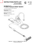
1
Spicer Drive Steer Axles
®
Service Manual
Spicer® Drive Steer Axles
AXSM-0051
September 2007
The description and specifications contained in this service
publication are current at the time of printing.
Dana Corporation reserves the right to discontinue or modify its
models and/or procedures and to change specifications at any
time without notice.
Any reference to brand name in this publication is made as an
example of the types of tools and materials recommended for use
and should not be considered an endorsement. Equivalents may
be used.
IMPORTANT NOTICE
This symbol is used throughout this
manual to call attention to procedures
where carelessness or failure to follow
specific instructions may result in
personal injury and/or component
damage.
Departure from the instructions, choice
of tools, materials and recommended
parts mentioned in this publication may
jeopardize the personal safety of the
service technician or vehicle operator.
WARNINGS: FAILURE TO
FOLLOW INDICATED PROCEDURES
CREATES A HIGH RISK OF
PERSONAL INJURY TO THE SERVICING
TECHNICIAN.
Caution: Failure to follow indicated
procedures may cause component
damage or malfunction.
Note: Additional service information not
covered in the service procedures.
Tip: Helpful removal and installation
procedures to aid in the service of this unit.
Always use genuine Spicer replacement parts.
2
Drive Steer Axle Wheel End
Contents
Important Notice ....................................................... 2
Introduction ............................................................. 4
Steer Axle Identitication .............................................. 4
Wheel End Identification ............................................. 5
Lubrication ............................................................. 5
Cleaning, Inspection, Repair and Replacement .................. 7
General Inspection .................................................... 8
Wheel Alignment and Wheel End Inspection ...................... 9
Wheel End Removal ................................................. 11
Hub and Drum Assemblies
16K, 18K and 21K Hub and Drum Explode ........................ 12
16K, 18K and 21K Hub and Drum Parts List ...................... 12
23K Hub and Drum Explode ......................................... 13
23K Hub and Drum Parts List ....................................... 13
Hub and Drum Removal ............................................. 14
Hub and Drum Reassembly ......................................... 16
Model EDS16S, EDS18S, EDS21S
Axle End Kit 21K Explode (16K and 18K Similar) ................ 18
Axle End Kit 21K Parts List (16K and 18K Similar) .............. 19
Front Axle Disassembly ............................................. 20
Inspection .............................................................. 21
Front Axle Assembly ................................................. 22
Model EDS23S
Axle End 23K Kit Explode ............................................ 26
Axle End Kit 23K Parts List .......................................... 27
Drive Steer Axle Wheel End Disassembly ........................ 28
Inspection and Repair ............................................... 32
Drive Steer Axle Wheel End Assembly ............................ 33
Fastener Torques ..................................................... 39
3
Drive Steer Axle Wheel End
Introduction
Steer Axle Identification
This manual includes instructions for the following Spicer
Drive Axles;
The complete axle is identified by the specification number
stamped on a metal tag attached to the rear right-hand side of
the axle housing. This number identifies all component parts of
the axle as built by Spicer, including special OEM requirements
such as yoke or flange.
•
•
•
•
EDS16S
EDS18S
EDS21S
EDS23S
Description and Operation
The front axle is a driving, full-floating axle. Garden type universal
joints enclosed in a hollow ball at the end of the axle housing
provide driving power and maintain steering control.
The jointed end of the axle shaft passes through a skein, a hollow
spindle with mounted wheel bearings. The skein attaches to a ball
socket, a one-piece housing surrounding the axle ball.
The axle housing is one piece. A ball and socket assembly and
wheel end equipment are attached to each end of the housing.
For service information on differentials, refer to separate service
manuals listed on the back cover of this manual.
EDS - 18S
Axle Gearing Types*
*S-Single Reduction
*Single Reduction with
Controlled Traction
Differential
*T-dual Range
*P-double Reduction
Axle Capacity
(X 1000) 18,000 Ibs.
Drive Steer
Spicer
This information applies only to the axle housing and should be
used when servicing the housing.
PT. NO. − Part number for axle housing only
HSG. CAP − GAWR for axle housing
− Identification number for axle housing only
HSG. I.D. No.−
HOUSING MADE IN − Indentifies manufacturing location
of axle housing
4
Drive Steer Axle Wheel End
Wheel End Identification
Lubrication
The tag attached to the wheel end identifies the wheel
end assembly.
To assure quiet, trouble-free operation over a period of years, use
approved gear lubricant in correct quantities. The following
lubrication instructions represent the most current recommendations from the Dana Corporation, Axle & Brake Division.
Do not use separate oil additives and/or friction modifiers in
Spicer Drive Axles.
Approved Lubricating
Approved Lubricants-General: Gear lubricants acceptable under
military specification (MILSPEC) MIL-L-2105D (Lubricating Oils,
Gear, Multipurpose) are approved for use in Spicer Drive Axles.
The MIL-L-2105D specification defines performance and viscosity
requirements for multigrade oils. It supersedes both MIL-L-2105B,
MIL-L-2105C and cold weather specification MIL-L-10324A. This
specification applies to both petroleum-based and synthetic-based
gear lubricants if they appear on the most current “Qualified
Products List” (QPL-2105) for MIL-L-2105D.
Approved Lubricants-Synthetic Based: Synthetic-based gear
lubricants exhibit superior thermal and oxidation stability, and
degrade at a lower rate when compared to petroleum-based
lubricants. The performance characteristics of these lubricants
include: extended change intervals, improved fuel economy, better
extreme temperature operation, reduced wear and cleaner component appearance. Spicer gear lubricants are premium
quality synthetic lubes which fully meet or exceed the requirements of MIL-L-2105D. These products, available in both 75W-90
and 80W-140, provide superior performance in comparison to
others qualified under the MILSPEG, as demonstrated by extensive laboratory and field testing.
Lube Sampling and Condition Monitoring: For information,
contact your local Spicer representation, listed on the back cover of
this manual.
Makeup Lube: Maximum amount of non-synthetic makeup lube
is 10%.
5
Drive Steer Axle Wheel End
Viscosity/Ambient Temperature Recommendations: The
following chart lists the various SAE Grades covered by MIL2105D
and the associated ambient temperature range for each. Those
SAE Grades shown with an asterisk (*) are available in the Spicer
family of synthetic gear lubricants.
Grade
75W
75W-80
75W-90*
75W-140
80W-90
80W-140*
85W-140
Ambient Temperature Range
-40°F to -15°F (-40°C to -26°C)
-40°F to 80°F (-40°C to 27°C)
-40°F to 100°F (-40°C to 38°C)
-40°F and above (-40°C and above)
-15°F to 100°F (-26°C to 38°C)
-15°F and above (-26°C and above)
10°F and above (-12°C and above)
When changing lubricant, Spicer recommends:
• Changing the oil filter
• Cleaning
− magnetic filler plug
− screen
− drain plug
− breather
Changing Lube
Draining
Tip: Drain when the lube is at normal operating temperature.
Lube will run freely and reduce drainage time.
The lowest ambient temperatures covered by this chart are -40 F
and -40 C. Lubrication recommendations for those applications
which consistently operate below this temperature range, are
available from Dana Corporation, Axle & Brake Division.
To drain:
Lube Change Intervals
3. Inspect drain plug for large quantities of metal particles. After
initial oil change, metal particles indicate damage or extreme
wear in the axle, and warrant inspection of the entire unit.
Lubrication Change Intervals-General: The initial lubricant
change improves axle component life and durability by removing
break-in contaminants from the system. These contaminants are
primarily metal from the initial break-in wear of rotating components, and silicon from the sand used in manufacture of cast
components.
For either a new or rebuilt drive axle, the lubricant should be
changed within the first 3000 to 5000 miles of operation. Refer
to the following chart for subsequent lubricant changes. Lube
changes may vary from those recommended in this chart based
on the application and operating environment.
Lubrication Change Intervals-Severe Service: Severe service
applications are those which require the axle to be consistently
operated near maximum GCW or GVW ratings, dusty or wet
environments, or consistent operation grades greater than 8%.
For these applications, refer to the ON/OFF HIGHWAY portion of
1. Unscrew the magnetic drain plug on the underside of the axle
housing.
2. Drain lube into a suitable container.
4. Clean and replace drain plug.
Filling
To add lube, remove the filler hole plug from the center of the
axle housing cover. Fill the axle with approved lubricant until level
with bottom of hole.
Tip: Lube fill capacities may vary.
Always use the filler hole as the final reference. Lube should be
level with the bottom of the hole.
Axles installed at angles exceeding 10° or operated regularly in
areas of continuous and lengthy grades may require standpipes
to allow proper fill levels.
For specific recommendations, contact you local Spicer representative, listed on the back cover of this manual.
Guidelines-Lube Change Intervals for Drive Axles
Maximum Change
Interval
Maximum Change
Interval
On/Off Highway Severe
Service Miles
Maximum Change
Interval
Petroleum
Based
100,000
Yearly
40,000
Yearly
Synthetic
Based
200,000
3 Years
80,000
Yearly
Spicer™
Synthetic
250,000
3 Years
100,000
Yearly
Lubricant Type
6
Drive Steer Axle Wheel End
Cleaning, Inspection, Repair and Replacement
As the wheel end is disassembled, set all parts aside for thorough
cleaning and inspection. Careful inspection will help determine
whether parts should be reused. In many cases, the causes of
premature wear or failure will also be revealed.
Cleaning
Assembles may be steam cleaned while mounted to the housing
as long as all openings are tightly plugged. Once removed, do not
steam clean any components. Steam cleaning at this time could
allow water to be trapped in passages, leading to rust, lubricant
contamination, and premature component wear. The only proper
way to clean the assembly is to disassemble it completely. Other
methods will not be effective except as preparatory steps in the
process. Wash steel parts with ground or polished surtaces in
solvent. There are many suitable commercial solvents available.
Kerosene and diesel fuel are acceptable.
WARNING: GASOLINE IS NOT AN ACCEPTABLE
SOLVENT BECAUSE OF ITS EXTREME
COMBUSTIBILITY. IT IS UNSAFE IN THE WORK SHOP
ENVIRONMENT.
Wash castings or other rough parts in solvent or clean in hot
solution tanks using mild alkali solutions. If a hot solution tank is
used, make sure parts are heated thoroughly, before rinsing.
Rinse thoroughly to remove all traces of the cleaning solution.
Dry parts immediately with clean rags.
Lightly oil parts if they are to be reused immediately. Otherwise,
coat with oil and wrap in corrosion-resistant paper. Store parts in
a clean, dry place.
Inspection
Inspect steel parts for notches, visible steps or grooves created
by wear. Look for pitting or cracking along gear contact lines.
Scuffing, deformation or discoloration are signs of excessive heat
in the axle, usually related to low lubricant levels or improper
lubrication practices.
Before reusing a gear set, inspect teeth for signs of excessive
wear. Check tooth contact pattern for evidence of incorrect
adjustment.
Inspect fasteners for rounded heads, bends, cracks or damaged
threads. Examine the axle housing for cracks or leaks. Also look
for loose studs or cross-threaded holes.
Inspect machined surfaces for nicks and burrs.
Repair and Replacement
Important: To achieve maximum value from an axle
rebuild, replace lower-cost parts, such as thrust washers,
seals, etc. These items protect the axle from premature
wear or loss of lubricants. Replacing these parts will not
increase rebuild cost significantly.
It is also important to replace other parts which display signs of
heavy wear even though not cracked or broken. A significant portion
of such a part’s useful life has been expended and the damage
caused, should the part fail, is far in excess of its cost.
Important: LH & RH wheel ends are different. Be sure to
identify parts and keep them separate.
Steel Parts - Gear sets, input and output shafts, differential parts and
bearings are not repairable. Worn or damaged parts should be
discarded without hesitation. Also discard mating parts in some
cases. Gear sets, for example, must be replaced in sets.
Miscellaneous parts - Seals and washers are routinely replaced.
None of these parts can be reused if damaged. Fasteners using selflocking nylon “patches” may be reused if not damaged, but should
be secured by a few drops of Loctite #277 on the threaded surface of
the hole during installation and carefully torqued during installation.
Axle Housings - Repairs are limited to removal of nicks or burrs on
machined surfaces and the replacement of loose or broken studs.
Caution: Any damage which affects the alignment or
structural integrity of the housing requires housing
replacement. Repair by welding or straightening should
not be attempted. This process can affect the housing heat
treatment and cause it to fail completely when under load.
Silicone Rubber Gasket Compound - For more effective sealing,
Spicer uses silicone rubber gasket compound to seal the majority of
metal-to-metal mating surfaces.
Spicer includes gasket compound and application instructions in
many repair parts kits.
It is recommended that this compound be used in place of conventional gaskets. The compound will provide a more effective seal
against lube seepage and is easier to remove from mating surfaces
when replacing parts.
Always use Spicer Genuine Axle Parts and Parts Kits
Genuine Spicer replacement parts are the same high quality as the
original components and include the latest engineering improvements.
Parts kits have only one part number which makes ordering,
stocking and servicing easier. They are not only convenient, but give
the advantage of having every part needed for a good repair job.
7
Drive Steer Axle Wheel End
General Inspection
Wheels
Wheel Alignment
Routine check of:
Proper wheel alignment promotes longer tire wear, provides ease of
handling, and minimizes strain on front suspension and axle
components.
Caution: Do not check and adjust front wheel alignment
without first making the following inspection for front end
improper adjustment, damage or wear:
1. Check the air pressure in all the tires. Make sure that the
pressures agree with those specified for the tires and vehicle
model being checked.
Wheel Stud Nuts
Wheel stud nuts should be inspected and tightened twice in the
first 500 miles, and again after 1,000 miles to avoid accidental
loosening of the wheels. Loose wheel stud nuts can cause
shimmy, vibration and elongated stud holes in the wheels.
2. Raise the front of the vehicle off the floor. Grasp each front
tire at the front and rear, and push the wheel inward and
outward. Adjust the wheel bearings if free play occurs
between the brake drum and the brake backing plate.
Wheel and Hub
3. Check brakes for dragging.
Check for damage that would affect the runout of the wheels.
4. Check all steering linkage for wear or improper adjustment.
Replace worn parts.
Wheel Rim
5. Check the steering gear mounting bolts, and tighten to
specification if required.
Inspect the wheel rims for dents that could permit air to leak
from the tires.
6. Check the front spring clips (U-bolts) and the spring tie bolt.
Tighten if required.
Tires
7. Spin each front wheel with a wheel spinner. Check and
balance each wheel as required.
8. Rotate each front wheel slowly, and observe the amount of
lateral or side runout. If the wheel runout exceeds 1/8′′,
replace the wheel or install the wheel on the rear.
Front Wheel Bearings
Replace front wheel bearings when excessively worn or damaged.
Check the bearing cups for proper installation before removing
them for replacement. If a cup is improperly seated in the hub,
inspect the hub for burrs, rough spots, or other irregular surfaces
that would prevent seating the cup properly.
Tip: Bearing damage is offen caused by lack of lubrication or
improper adjustment. When installing bearing cups or cones and
rollers, use the specified lubricant and adjust the bearings. Wobble
or shimmy caused by a damaged wheel will eventually damage the
wheel bearings.
8
• Wheel stud nuts
• Wheel and hub
• Wheel rim
Keep the wheels and hubs clean. Stones or lumps of mud wedged
between the wheel and drum will unbalance a wheel and tire.
1. Check tires frequently to be sure that the air pressures
agree with those specified for the tires and vehicle model.
2. Inspect the tire treads and remove all stones, nails, glass,
or other objects that may be wedged in the tread. Check
for holes or cuts that may permit air leakage from the tire.
Make the necessary repairs.
3. Inspect the tire side walls for cuts, bruises, and other
damage. If internal damage is suspected, demount the tire
from the wheel for further inspection and repair.
4. Check the valve for air leaks. Replace the valve if
necessary. Replace any missing valve caps.
Drive Steer Axle Wheel End
Wheel Alignment and Wheel End Inspection
Caster Angle
Tie Rod and Tie Rod Ends
Caster angle is the degrees the top of the kingpin inclines toward
the front or rear of the vehicle. (See Figure 2). Caster angle is
viewed from the side of the vehicle. The caster angle ranges from
a positive to a negative angle.
Tie rods consist of:
•
•
Tie rod
Two rod end assemblies
The ends are threaded to the rod and locked with clamp bolts.
Right and leff hand threads provide for toe-in adjustment. Ball
stud tension in the tie rod ends self-adjusts. Periodically inspect
to see that the ball studs sit tight in the steering knuckle arms.
Fittings allow lubrication of some tie rod ends. Where no fittings
are used, the tie rods have been lubricated at assembly and do
not require further lubrication.
Wheel End Alignment Factors
To check wheel alignment, or when installing new axle parts,
check the following on both wheels:
A positive caster indicates that the top of the kingpin tilts toward
the rear of the truck and imparts a trailing action to the front of
the wheels. Negative, or reverse caster, tilts toward the front of
the truck and causes a leading action. The correct amount of
caster helps to keep the wheels in the straight-ahead position.
When turning a curve, caster acts as a lever to return the wheels
to the straight-ahead position.
Caster specifications are set in all new vehicles. However,
variations in spring equipment, type of service, tire, wheel size or
wheel base may make a slight change in caster angle desirable to
provide the best possible steering stability. The caster angle must
be equal at both wheels.
1. Camber Angle
2. Caster
3. Toe-in
Camber Angle
Unequal camber in the front wheels causes the truck to lead to
the right or leff. The truck will lead to the side which has the most
positive camber. Normal camber angle is 1/2 degree.
Camber is nonadjustable. Damage will change the angle of the
axle ball assembly or axle housing.
Figure 2 Caster Angle
Figure 1 Chamber Angle
9
Drive Steer Axle Wheel End
Toe-in Adjustment with Tires On
Toe-in is set at 0′′ to 1/8′′. The front and the rear of the wheels
should be the same distance apart or the front should be 1/8′′
closer than the rear.
Change adjustment by turning tie rod to change its length.
Adjustment can be checked as follows (See Figures 3 and 4):
1. Scribe a line at center of each tire tread completely
around the tire by rotating wheel while holding chalk
against tire tread. Line must begin and end at the same
point. (See Figure 3).
Toe-In Adjustment with Tires Off
1. With tires off, place two straight edges approximately
50′′ long against wheel mounting surfaces.
2. Measure between or over the straight edges. The
dimensions at the front side of the axle should be equal
to or 1/8′′ less than the dimensions measured at the rear
side of the axle.
3. Adjust as necessary.
2. Measure the line on the axle centerline at front of the
tires. (See Figure 4).
3. Repeat measurement at rear of tires.
4. Compare measurements. Front measurement (A) should
be the same or 1/8′′ shorter than rear measurement (B).
5. Adjust tie rod as required.
Figure 4 Measure Toe-in
Figure 3 Scribe Tires
10
Drive Steer Axle Wheel End
Wheel End Removal
Tip: This procedure is used only when servicing the carrier
assembly.
Both left-hand and right-hand wheel ends are removed the same
way, except where otherwise specified. Face the differential
carrier side of the axle to differentiate between left-hand and
right-hand.
WARNING: DO NOT LIE UNDER CARRIER AFTER
FASTENERS ARE REMOVED. USE TRANSMISSION
JACK TO SUPPORT AND REMOVE DIFFERENTIAL
CARRIER ASSEMBLY.
To remove wheel end:
1. Drain axle lube.
2. Separate wheel end assembly from axle housing by
removing capscrews and nuts fastening socket ball to
the housing.
3. Disconnect air brake lines and steering connections as
required to permit moving the wheel end assembly
outwards until the axle shaft disengages from the
differential side gear. Disengage axle shaft on both
sides of axle.
Figure 5 Remove Wheel End Assembly from housing
11
Hub and Drum Assemblies
Hub and Drum Assemblies
Figure 1 16K, 18K and 21K Hub and Drum Assembly
16K, 18K and 21K Hub and Drum Assembly Parts List
ITEM NO.
DESCRIPTION
ITEM NO.
DESCRIPTION
39.
47.
48.
51.
52.
53.
54.
55.
Skein, Front Axle
Drum, Brake
Stud, Mounting
Seal, Hub Oil
Spacer, Oil Seal
Cone, Hub Bearing
Cup, Hub Bearing
Hub, Front
56.
57.
58.
59.
60.
61
62.
Capscrews, Bearing Nut
Nut, Wheel Assembly
Gap Assy
Capscrew
Capscrew
Lock, Bearing Nut
Lockwasher
12
Hub and Drum Assemblies
Figure 2 23K Hub and Drum Assembly
23K Hub and Drum Assembly Parts List
ITEM NO.
DESCRIPTION
ITEM NO.
DESCRIPTION
33.
39.
40.
41.
42.
43.
44.
45.
46.
Skein, Front Axle
Seal, Hub Oil
Spacer, Oil Seal
Cone, Hub Bearing
Cup, Hub Bearing
Hub, Front
Drum, Brake
Capscrew
Capscrew
47.
48.
49.
50.
51.
52.
53.
54.
55.
Lockwasner
Capscrew
Cap Assy
Nut, Wheel Bearing
Capscrew, Bearing Nut
Lockwasher
Lock, Bearing Nut
Tack
Plate, ID
13
Hub and Drum Assemblies
Hub and Drum Removal
To disassemble:
1. Remove attaching stud nuts and Iockwashers.
2. Remove the hubcap with puller screws in the holes.
(See Figure 3).
Note: Capscrews in the puller holes during vehicle operation will
protect the threads.
3. Remove bearing nut lock, lockwasher and bearing nut
capscrews. (See Figure 4).
4. Remove wheel bearing nut. (See Figure 5).
5. Pull the outer cone away from the axle and remove the
outer wheel bearing cone. (See Figure 6).
Caution: If reusing the cones, keep matched sets and
reinstall in original location.
6. Drive out the oil seal (39) and the wheel bearing spacer (40).
7. Lift out the inner wheel bearing cone. (See Figure 7).
Caution: Never remove the cups in the hubs unless
replacing them due to pitting, scoring or other damage.
Insert a driver into the hub grooves to remove cups.
Figure 3 Removing Hupcap
14
Figure 4 Removing Bearing Nut Lock
Figure 5 Removing Wheel Bearing Nut
Hub and Drum Assemblies
Figure 6 Removing Hub Bearing Cone
Figure 7 Removing Inner Bearing
15
Hub and Drum Assemblies
Hub and Drum Reassembly
1. If replacing wheel bearings, press the outer and inner wheel
bearing cups into the hub. Install the cups with the race
facing outwards. Be sure the cups are fully seated on the
shoulder of the hub bore.
2. Line the entire inner wall of the hub with grease. Pack inner
wheel bearing cone.
3. Place the inner wheel bearing cone into the inner bearing
cup. Install bearing spacer on top of bearing cone.
(See Figure 8).
4. Position wheel bearing oil seal so that the lip faces inwards.
Tap the seal flush with the edge of the hub face.
(See Figure 9). Coat the lip of the seal with grease and
make sure the seal spring is in position.
Caution: There will be slack between the cone, spacer
and seal. This will be taken up when the wheel bearing
lock nut is adjusted. Do not force the seal to take up
the slack.
5. Grease the axle skein lightly. Slide hub and drum assembly
over the skein and brake assembly. Make sure the
assembly is on the skein as far as possible.
Figure 9 Installing Oil Seal
6. Pack the outer wheel bearing cone. Slide outer wheel
bearing cone into the outer wheel bearing cup in the hub.
7. Turn the wheel bearing nut onto the skein until it is tight
against the outer wheel bearing cone. Torque nut to about
100 lb. ft. (136 N•m) to seat bearings. Back off to the
closest slot.
Figure 10 Installing Wheel Bearing Nut
Figure 8 Installing Inner Bearing
16
Hub and Drum Assemblies
8. Measure the hub (43) rotating drag by pulling at the wheel
studs. Proper drag is 4-10 pounds to keep (not start) the
hub turning. Adjust wheel bearing nut (50) as required to
set proper drag.
9. Install the bearing lock into the slot in the lock nut that lines
up with a slot in the axle skein (33). Install capscrew and
lockwasher to secure bearing lock in place. Torque
capscrew to 25 lb. ft. (34 N•m) wet.
10. Pack the groove inside the hubcap with a layer of grease
about 1/2′′ thick. Use a soft hammer to drive the hubcap
onto the studs.
11. Install lockwashers and nuts on the hub assembly. Torque
nuts to 130 lb. ft. (176 N•m) wet.
12. Install capscrews in hubcap puller screw holes to
protect threads.
13. Connect air brake line at air chamber (36).
14. Adjust brake shoes.
15. Connect steering drag link and tie rod.
16. Install coffer pins in drag link.
Figure 12 Tightening Lock Nut
Figure 11 Measuring Hub Rotating Drag
Figure 13 Installing Hupcap
17
16K, 18K and 21K Drive Steer AxleWheel End
Model EDS16S, EDS18S, EDS21S
Figure 1 Axle End Kit 21K (16K and 18K similar)
18
16K, 18K and 21 K Drive Steer Axle Wheel End
Axle End Kit 16K-21K Parts List
ITEM NO.
1.
2.
3.
4.
5.
6.
7.
8.
9.
10.
11.
12.
13.
14.
15.
16.
17.
18.
19.
20.
21.
22.
23.
24.
25.
26.
27.
28.
29.
30.
31.
32.
DESCRIPTION
Seal, Housing Oil
Ball, Axle
Capscrew
Plate, End
Trunnion
Retainer, Seal
Seal, Socket
Stud
Steering Arm
Nut,Hex
Lockwasher
Dowel
Fitting
End, Tie Rod, RH
Bearing,Top
Ball Socket
Seal, Oil
Tie Rod
End, Tie Rod, LH
Shaft, Inner Axle
Cage Ring Assembly
Shaft, Outer Axle
Bolt
Plug, Pipe
Lockwasher
Cover, Bottom
Shim
Bearing, Bottom
Nut, Hex
Screw, Stop
Lockwasher
Capscrew
ITEM NO.
33.
34.
35.
36.
37.
38.
39.
40.
41.
42.
43.
44.
45.
46.
47.
48.
49.
50.
51.
52.
53.
54.
55.
56.
57.
58.
59.
60.
61.
62.
63.
64.
DESCRIPTION
Bushing
Pin, Spring
Brake Spider & Pin Assy
Yoke
Brake Chamber
Anchor, Control Arm
Skein, Front Axle
Slack Adjuster
Spacer
Bracket Assy, Chamber Mounting
Fitting
Capscrew
Lockwasher
Brake Kit
Drum, Brake
Stud, Mounting
Capscrew
Washer, Plain
SeaI,Hub Oil
Spacer, Oil Seal
Cone, Hub Bearing
Cup, Hub Bearing
Hub, Front
Capscrew, Bearing Nut
Nut, Wheel Bearing
Cap Assy
Capscrew
Capscrew
Lock, Bearing Nut
Lockwasher
Tack
Plate, ID
19
16K, 18K and 21K Drive Steer Axle Wheel End
Front Axle Disassembly
Axle Shaft, Hub, Bearing and Seal Removal
WARNING: PARK VEHICLE ON LEVEL GROUND AND
SUPPORT FRONT AXLE ON JACK STANDS TO
PREVENT INJURY.
The right and left axle parts are similar. When it is necessary to
remove the axle, ball and socket, remove as an assembly. The
following procedures will work for either side. To repair front axle:
1. Drain axle lubricant.
2. Remove (Refer to Hub & Drum Removal, page 15):
•
•
•
•
•
Tire
Wheel
Brake drum
Camshaft
Brake shoes
3. Remove ten bolts (60) and two bolts (59) from cap (58).
4. Attach a slide hammer to cap (58) where two bolts (59)
were removed.
5. Remove cap (58) from hub (55) with slide hammer.
6. Remove the following from bearing nut (57)
:
• Bolt (56)
• Lockwasher(62)
• Bearing nut lock (61)
Figure 2 Match Marking Axle Shaft
20
7. Remove bearing nut (57) from skein (39) using wheel
bearing wrench.
8. Remove outer bearing cone (53) from hub (55). If reusing
bearing cone, keep in matched sets and tag for proper
reassembly.
9. Remove hub (55) from skein (39).
10. Using drift, drive seal (51) and spacer (52) from hub (55).
11. Remove inner bearing cone (53) from hub (55).
12. If bearing cups (54) are worn or damaged, use a drift to
drive both bearing cups from hub (55).
13. Mark spider and ball socket for proper reassembly.
Remove ten bolts (49) and washers (50) from skein.
Remove skein (39) and spider (35) from ball socket (16).
14. Turn ball socket to straight ahead position. Garefully pull
axle shaft and cage ring assembly from axle.
15. Mark cage ring halves and both axle shafts using a
punch. (See Figure 2).
16. Remove eight bolts using an allen head wrench.
(See Figure 3).
17. Separate shafts (20 and 22) by removing cage ring halves
(21). Remove pin, if damaged.
Tip: If replacing ball socket or related parts, continue with Ball
and Socket Removal procedure (page 21). If not, clean all parts,
then go to Inspection procedure (page 21).
Figure 3 Separating Cage Rings
16K, 18K and 21K Drive Steer Axle Wheel End
Ball and Socket Removal
To remove ball and socket:
Tip: Mark all ball socket parts before removal.
1. Mark location of clevis and remove from slack aduster (40).
2. Remove brake chamber bracket (42) from ball socket (16).
Leave air line connected to chamber (37). Hang chamber
and bracket out of the way. Do not hang by air line.
3. Remove slack adjuster (40) and camshaft.
4. Disconnect tie rod (18) from ball socket (16) by removing:
• Gotter pin
• Nut
• Washer
5. Separate tie rod end (19) from ball socket (16).
6. When working on the left side, disconnect steering linkage
by removing cotter pin and nut and dislodging ball joint
from steering arm (9).
Inspection
Axle Shaft and Cage Ring
To check clearance between axle shafts and cage ring:
1. Measure axle shaft trunnions. (See Figure 4).
2. Assemble cage ring halves and measure bore. (See Figur 4).
3. If the difference between these two measurements exceeds
.050′′, replace parts.
Bushing
If axle ball (2) was replaced, inspect the bushing (33) as follows:
1. Measure machined surface of inner axle shaft with a
micrometer. Shaft must measure a minimum of 2.50′′.
2. Measure inner diameter of bushing (33).
3. If the difference between the two measurements exceeds
0.015′′, replace worn parts.
Carefully inspect all other parts for damage or wear.
7. Remove steering stop screw (30) and nut (29).
8. Remove bolts (32) and lockwashers (31).
. 9. Carefully pry out seal retainers (6) and oil seal (7).
10. Remove top cover (4) and bottom cover (26) by removing
bolts (23) and washers (25). To remove upper cover on lefthand ball socket: spread and remove dowels on the steering
arm by inserting a screwdriver in the split and lifting
upwards. Record number and thickness of shims (27) used
under bottom covers (26).
11. Remove bolts (3) and end plates (4) from top and bottom.
Use a drift to drive out trunnions(5).
12. Keeping both bearing cones (15 and 28) seated in their cups,
carefully drive ball socket (16) down. This forces upper
bearing cup out of its bore. Force bearing cup up at least
1/8′′. Drive ball socket up to force bottom cup out at least 1/8′′.
13. Tip ball socket (16) away and remove it from axle ball (2)
while holding upper bearing cone in its cup.
14. Remove bearing cones (15 and 28). Drive out bearing cups.
Tip: If bearings will be reused, label as top or bottom and
keep separate.
15. Remove:
• Bolts
• Lockwashers
• Axle ball (2) from axle housing
• Housing oil seal (1)
Figure 4 Check Axle Trunnion Wear
21
16K, 18K and 21K Drive Steer Axle Wheel End
Front Axle Assembly
Bushing
Caution: All bearings and oil seals must be lubricated
during assembly. Use grease to coat thoroughly.
If bushing (33) was removed, install as follows:
1. Place bushing with beveled end facing into axle ball.
2. Firmly seat bushing using a press.
3. Ream bushing as required to provide a 0.003 to 0.005′′
clearance with axle shaft.
Ball and Socket Installation
1. Install:
• Oil seal (1) with lip facing up, away from axle baIl (2)
• Oil seal retainers (6)
• Oil seal (7) over axle housing end
2. Goat mating surfaces of the axle housing and ball socket
(16) with sealant.
22
3. Attach axle baIl (2) to axle housing, in a vertical
position, secure with large and small bolts and large and
small Iockwashers.
• Torque small bolts to 187 lb. ft. (253• N.m)
• Torque large bolts to 400 lb. ft. (542•N.m)
4. Tip ball socket (16) and install over baIl (2).
5. Install top and bottom trunnions (5). Use a spreading
fixture to hold in place.
6. Install bearing cones (15 and 28) and seat firmly on
trunnions (5).
7. Install bearing cups (15 and 28) and seat firmly on cone.
8. Install bottom cover (26) with same shim pack (27) that
was removed unless ball socket (16), axle ball (2), or any
trunnion bearings were replaced. If any of these parts were
replaced, install a new shim pack of .045′′.
Tip: Shims are used to preload the trunnion bearings and to
center the axle socket. No shims are used under upper trunnion
cover or steering arm.
16K, 18K and 21K Drive Steer Axle Wheel End
9. Install bottom cover (26) and top shims (27) with:
• Lockwashers (25)
• Bolts (23)
10. Install upper cover or, if working on left side, steering
arm with:
•
•
•
•
Stud (8)
Dowel (12)
Lockwashers(11)
Nuts(10)
Note: Make sure steering arm is installed with finished surface
toward bearing.
11. Torque lower cover bolts to 187 lb. ft. (253 N•m). Remove
pipe plug (24) from lower cover and temporarily install a
grease fitting. Tighten upper cover bolts to give ball socket
a slight amount of drag.
12. Lubricate both trunnion bearings through upper and lower
fittings with grease gun. Grease until it can be seen inside
ball socket, coming through bearing cones.
13. Remove spreading fixture. Torque upper cover bolts or
steering arm nuts to 320 lb. ft. (434 N•m).
15. Change shim pack (27) to correct bearing preload or to
center axle socket.
16. Fill trough between back of ball socket and ball with grease.
17. Remove lower grease fitting and install pipe plug (24).
18. Push retainers (6) and seal (7) into ball socket. Tap retainer
into place.
19. Coat capscrew (32) with Loctite and install with Iockwashers
(31). Torque to 12 lb. ft. (16 N•m).
20. Install steering stop screw (30) with nut (29). Do not adjust
at this point.
21. Turn ball socket against stop. Coat inside with grease. Turn
socket the other way, and coat with grease.
22. Connect tie rod end to ball socket. Install washer and nut.
Torque nut to 110-125 lb. ft. (136-169 N•m). Install new
cotter pin.
23. Connect ball joint to steering arm (9). Torque nut to
110-125 lbs. ft. (136-169 N•m). Install new cotter pin if
working on left side.
14. Use a spring scale to check bearing preload. To maintain
ball socket movement requires a pull of about 38-42 lb. ft.
(52-57 N•m). Ball socket must never contact or rub on axle
ball at any position.
23
16K, 18K and 21K Drive Steer Axle Wheel End
Axle Shaft, Hub, Bearing, and Seal Installation
1. Install appropriate cage ring half (21) over axle shaft (20
and 22).
2. Lightly coat cage ring bores and axle shaft trunnions
with grease.
3. Align cage rings and shafts using punch marks made
during disassembly.
4. Install and tighten eight bolts into cage rings. Axle shafts
must move freely at least 30° on both sides of cage ring.
5. Torque bolts to 90 lb. ft. (122 N•m).
6. Turning ball socket straight ahead, grease axle shaft
bushing in axle ball.
7. Pack inner walls of axle ball with 3/4′′ of grease, but leave
axle shaft hole clear.
8. Remove all nicks or burrs from axle splines.
Caution: Nicks or burrs will damage axle housing oil
seal if not removed.
9. Install axle shaft (20) into ball socket (16).
Caution: Be careful to not damage oil seal when
installing axle into housing.
10. Completely cover cage rings (21) with excess grease.
11. Coat the following mating surfaces with sealant:
• Ball socket (16)
• Brake spider (35)
• Skein (39)
12. Install spider (35) and skein (39) in same position as
disassembly using ten bolts (49) and plain washers (50).
Torque bolts (49) to 187 lb. ft. (253 N•m).
13. Install two bushings for the camshaft in ball socket (16).
(See Figure 5).
14. Install seal on slack adjuster side so the spring side faces
the slack adjuster. Install seal on brake assembly side so it
faces away from the brake assembly.
WARNING: PROPER SEAL INSTALLATION ALLOWS
GREASE TO ESCAPE DURING PRESSURE BUILD-UP
AND PREVENTS GREASE FROM ENTERING THE BRAKE
ASSEMBLY. GREASE IN THE BRAKE ASSEMBLY
COULD BE A SAFETY HAZARD.
15. Install shoes and camshaft.
16. Use a driver to install bearing cups (54) into hub (55) until
firmly seated.
17. Fill hub (55) with grease. Leave a hole large enough for
skein (39) to slide in. Coat seal and bearing surfaces of
skein (39) with a thin film of grease.
18. Use bearing packing tool to pack bearing cones (53) with
grease.
19. Install inner bearing (53) into rear of hub (55).
20. Install spacer (52) into hub (55) with inner bevel facing
outwards.
21. Install seal (51) into hub (55) using a driver. Press flush
with edge of hub and lip facing inwards.
22. Coat lip of seal (51) with grease.
23. Install hub (55) and drum (47) onto skein (39).
24. Install outer bearing (53) onto skein (39) and push into
hub (55).
25. Screw bearing nut (57) on skein (39), finger tight.
Caution: Torque nut (57) just enough to eliminate end
play in hub. Overtightening will cause excessive drag
and parts damage.
26. Eliminate end play by rotating hub (55) while tightening nut
(57) with wrench.
Figure 5 Camshaft Bushing Installation
24
16K, 18K and 21K Drive Steer Axle Wheel End
27. Back off nut to align slot in nut with nearest groove in skein
(39). If nut (57) tightens halfway between slots in skein
(39), remove and turn it over to obtain proper alignment.
28. Use wrench to install:
• Lock plate (61) into slot in nut (57)
• Lockwasher (62)
• Bolt (56) and tighten bolt securely
29. Pack groove of hubcap (58) with grease and coat mating
surface of cap with Loctite.
30. Install hubcap on hub (55) with ten bolts (60).
31. Torque bolts (60) to 187 lb. ft. (253 N•m).
32. Install two bolts (59) in hubcap (58). Torque bolts (59) to
55 lb. ft. (75 N•m).
33. Adjust toe-in if ball sockets or trunnion bearings were
removed or if original adjustments were changed. This
truck requires 0-1/8′′ toe-in. (See Toe-in Adjustment on
page 11).
34. Adjust steering stops if ball sockets or trunnion bearings
were removed or if original adjustments were changed.
Adjust stop bolt to 27°. Measure at steering arm.
(See Figure 6).
Figure 6 Steering Stop Adjustment Left-Hand Turn
To adjust:
•
•
•
•
Turn wheels for a 27° turn, measured at steering arm.
Turn stop screw on ball socket out to contact axle.
Lock in place with lock nut.
Repeat for other side.
35. Install tire and wheel. Check steering for proper operation.
25
23K Drive Steer Axle Wheel End
Model EDS23S
Figure 1 Axle End Kit 23K
26
23K Drive Steer Axle Wheel End
Axle End Kit 23K Parts List
ITEM NO.
1.
2.
3.
4.
5.
6.
7.
3.
9.
10.
11.
12.
13.
14.
15.
16.
17.
18.
19.
20.
21.
22.
23.
24.
25.
26.
27.
28.
DESCRIPTION
Seal, Oil
Ball, Axle
Capscrew
Plate
Trunnion
Seal Plate
Seal
Stud
Steering Arm
Nut, Hex
Lockwasher
Dowel
Fitting, Lube
Tie Rod End, RH
Bearing
Socket, Ball
Tie Rod
Tie Rod End, LH
Shaft, Axle
Cage, Ring
Shaft, Ball
Plug
Nut, Hex
Lockwasher
Stud
Tie Rod Arm
Shim
Nut, Hex
ITEM NO.
29.
30.
31.
32.
33.
34.
35.
36.
37.
38.
39.
40.
41.
42.
43.
44.
45.
46.
47.
48.
49.
50.
51.
52.
53.
54.
55.
DESCRIPTION
Screw
Lockwasher
Capscrew
Bushing
Skein, Front Axle
Washer
Capscrew
Chamber, Air Brake
Nut, Collet
Brake Assy
Seal, Oil
Spacer
Bearing Cone
Bearing Cup
Hub, Front
Drum, Brake
Wheel Stud, Metric
Capscrew
Lockwasher
Capscrew
Cap Assy
Nut, Wheel Bearing
Capscrew
Lockwasher
Nut
Tack
Plate, ID
27
23K Drive Steer Axle Wheel End
Drive Steer Axle Wheel End Disassembly
1. Take off shoe retainer hardware and retractor springs to
remove both brake shoes. (Refer to Hub & Drum Removal,
page 15).
2. Loosen collet nut (37) on brake air chamber (36) and
unscrew entire assembly from brake anchor (38).
3. Remove:
•
•
•
•
28
Nuts
Lockwashers
Two capscrews
Brake shoe return spring bracket
4. Pull brake anchor assembly (38) away from the ball socket
(16) and remove.
5. Use a soft hammer to loosen the axle skein (33) from ball
socket (16).
Caution: Use care when tapping on the skein (33) to not
strike threads.
6. Place a pan under ball socket (16) to catch grease. Remove
skein (33) by pulling it away from the ball socket (16).
Figure 2 Removing Brake Shoes
Figure 4 Brake Removal
Figure 3 Removing Skein Nuts
Figure 5 Loosening Skein
23K Drive Steer Axle Wheel End
7. Position ball socket (16) straight ahead.
8. Pull on the ball shaft to remove the axle shaft (20 and 22)
and cage ring assembly (21).
Tip: Mark the ball sockets and parts, as you remove them. Keep
them separated so you can return them to their original positions.
9. Remove the ball seal capscrews and carefully pry out the
seal (7). (See Figure 8).
10. Remove:
• Tie rod arm (17) from boffom of ball socket (16)
• Steering arm (9) or booster arm from top of ball
socket (16)
• Dowels (12)
Figure 6 Removing Skein
Figure 8 Removing Seal Plate and Seal
Figure 7 Removing Axle Shafts and Cage Ring
Figure 9 Removing Cover and Shims
29
23K Drive Steer Axle Wheel End
11. Insert a screwdriver into the slot in the dowel, spread and
lift out the dowel. Take note of the quantity and thickness of
the shims removed from the top and bottom trunnions.
(See Figure 14).
Tip: Some of the axle models do not require shims on the
top trunnion.
12. Remove capscrews (3) and bearing retainer plate (4) from
upper and lower ball trunnions (5).
14. Keeping the trunnion bearing cones (15) fully seated, drive
the axle ball socket (16) down so the upper trunnion
bearing cup (15) moves up and out of the ball socket at
least 1/8′′ above the trunnion bearing cover parting surface.
Repeat for lower trunnion bearing. (See Figure 11).
15. Holding the upper trunnion bearing cone upward, tip the
ball socket housing and maneuver the bearing cone from
the axle ball. (See Figure 12).
13. Using a suitable drift, drive trunnions out of the ball socket.
(See Figure 10).
Figure 10 Driving Out Trunnions
Figure 11 Unseating Bearing Caps
30
Figure 12 Removing Ball Socket
Figure 13 Match Marking Axle Shafts and Cage Rings
23K Drive Steer Axle Wheel End
16. Carefully drive the trunnion bearing cups out of the socket
with an appropriate driver.
Caution: Mark the axle shafts (19 and 21), and cage ring
halves (20) before disassembling. The axle shaft yoke
trunnion must be reassembled into the same cage ring
holes to ensure proper operation.
19. Remove:
• Axle ball stud nuts
• Capscrews
• Axle ball from axle housing
20. Replace axle shaft oil seal in back end of ball.
17. Mark the cage ring (20) and shafts with a series of punch
marks to assure proper assembly sequence. (See Figure13).
18. Separate the ball shaft (21) from the axle shaft (19) using
an allen wrench to remove the capscrews that hold the cage
ring (20) together. (See Figure 14).
Figure 15 Axle Ball Shaft Seal
Figure 14 Separating Cage Rings
31
23K Drive Steer Axle Wheel End
Inspection and Repair
Caution: Replace damaged steering arms, knuckles, or
other steering components. Do not attempt to
straighten damaged parts. Replace all damaged
or worn parts. Do not weld or braze any of the
components in the steering or axle end assembly.
Inspection
1. Inspect the axle ball outside surface for excessively deep
grooves, scratches or damage.
2. Check the clearance between the axle ball bushing and the
axle shaft. If the clearance is more than .015′′, replace worn
parts. When replacing the ball bushing, press new bushing
in so that the open end of the grease slot faces towards the
outside of the axle ball. Ream bushing to provide .003-.005′′
clearance for the axle shaft.
3. Check the clearance between axle shaft trunnions and cage
ring holes. (See Figure 16). If the clearance is greater than
.050′′, replace worn parts.
4. Inspect all ball trunnion bearing cones and cups. If any
bearings are found to be defective, replace cup and cone as
a complete set.
5. Check the following for cracks:
•
•
•
•
Axle housing
Axleskein
Ball sockets
Axle balls
Caution: This check is very important if the truck has
been involved in an accident. Routinely use Magnaflux
or fluorescent penetration, if no accident is involved.
Repair
Repair consists of replacement of those components found
defective during inspection. Spicer recommends replacing the ball
dirt seal and axle shaft oil seal at each overhaul.
32
Figure 16 Check Axle Trunnion Wear
23K Drive Steer Axle Wheel End
Drive Steer Axle Wheel End Assembly
1. Install axle ball seal (7) and seal plate (6) over axle mounting flange. (See Figure 17).
2. Press axle shaft oil seal (1) into axle ball (2) with seal lip
facing out.
3. Apply RTV sealant to axle ball (2) and install ball onto studs
in axle housing and secure with nuts, capscrews, and
washers. Leave out the top two capscrews until after socket
turn angle stops are set. Torque all nuts and capscrews to
320 lb. ft. (434 N•m) wet.
Figure 17 Installing Axle Ball Seal
Figure 18 Installing Axle Ball Socket
4. Tip ball socket (16) and install over axle ball (2). (See
Figure 18).
5. Install top and bottom axle ball trunnions (5). Insert and
spread the trunnion spreading fixture against the head of
the trunnions. (See Figure 19).
6. Install trunnion bearing end plate (4) and capscrews (3).
Torque capscrews (3) to 40 lb. ft. (54 N•m) wet.
Figure 19 Installing Axle Ball Trunnions
Figure 20 Installing Trunnion Bearing End Plates
33
23K Drive Steer Axle Wheel End
7. Install the steering arm (9). Use dowels (12) on mounting
studs (8).
8. Install tie rod arm (26).
9. Install top and bottom bearing shims (27).
Tip: If either the ball socket, axle ball or any trunnion have been
replaced, begin with a trial shim pack of .045 inch.
10. Install tie rod arm (26) on bottom of ball socket (16) with
lock washers (24) and nuts (23). Tighten nuts (23) enough
to give a light amount of drag to the movement of the ball
socket (16). The trunnion spreading fixture is still installed
and will affect the drag on the socket.
16. Check the axle socket bearing preload. Approximately
38-42 lb. ft. (52-57 N•m) is required to keep the socket
moving after it is started. (See Figure 22).
17. Apply lubricant in the trough on the back side of the socket
between the socket and axle ball.
18. Remove grease fitting from the lower tie rod arm. Reinstall
pipe plug (22).
19. Coat mating surfaces of axle ball seal and ball socket with
RTV or equivalent. Assemble axle ball seal to ball socket
with cutout toward front. Secure with support washer and
capscrews. Torque capscrews to 25 lb. ft. (34 N•m) wet.
11. Check that the ball socket housing does not contact or rub
against axle ball at any position of its travel.
12. Adjust shims from top to bottom position to center axle ball
within socket. Use all shims to correctly preload bearings. If
either axle ball or socket has been replaced, it may be
necessary to grind material away from axle ball housing to
obtain required clearance.
Tip: With shims placed under steering arm and tie rod arm,
preload the trunnion bearings and center the axle ball within ball
socket housing. Models use either bottom and top shims or
bottom shims only.
13. Remove pipe plug (22) from tie rod arm (26) and install a
grease fitting.
14. Lubricate top and bottom trunnion bearings (15) until
grease comes through bearing cone.
Figure 22 Checking Ball Socket Drag
15. Remove trunnion spreading fixture and tighten upper
steering arm nuts (10).
Figure 21 Installing Steering Arm and Tie Rod Arm
34
Figure 23 Seal Plate and Seal
23K Drive Steer Axle Wheel End
20. Install steering stop screw (29) and lock nut (28) in front
ear of the ball socket (16) with machined head of the stop
screw facing towards the axle ball (2).
21. Set the steering stop screw so that the ball socket cannot
be turned to an angle greater than 25° with respect to the
ball flange.
Tip: Turn the ball socket (16) toward the front. Use a square and
machinist’s protractor, as shown in Figure 24, to adjust the turn
angle to 25°. Turn the stop screw (29) out until it hits the neck of
the ball (2) and lock in place with lock nut (28).
22. Install the last two capscrews and washer in axle ball (2).
Torque all nuts and capscrews in axle ball to 320 lb. ft.
(434 N•m) wet.
23. Place a thin layer of lubricant on the axle shaft trunnions
and also in the mating bores of the cage ring (20).
24. Use marks made during disassembly to slip the correct half
of the cage ring over the axle shafts. Insert and start the
capscrews, securing the cage ring halves together. (See
Figure 26).
25. Position and check the axle shafts to make sure that they
move freely to at least 30° on both sides of center during a
full 360° revolution. Torque the cage ring capscrews to
95 lb. ft. (129 N•m). Lock the capscrews with a punch mark
across the threaded end of the capscrew which extends
through the cage ring. (See Figure 27).
26. Turn the ball socket straight ahead.
Figure 26 Assembling Cage Ring Halves
Figure 24 Measuring Turn Angle
Figure 25 Axle Ball
Figure 27 Checking Cage Ring and Axle Shafts for Free Movement
35
23K Drive Steer Axle Wheel End
27. Grease the axle shaft bushing (32) in the axle ball (2) and
pack the inner walls of the axle ball (2) with about 3/4′′
thick layer of specified grease.
Caution: Leave the axle shaft hole clear.
28. Polish the end of the splines of the axle shaft (19) to
eliminate all nicks and burrs.
Caution: Failure to remove nicks and burrs will result in
damage to the axle housing oil seal (1) during axle shaft
installation.
29. Grease all polished surfaces of the axle shaft (19).
30. Install the axle shaft (19), being careful not to damage the
axle housing oil seal (1).
31. Spread grease to completely cover the ring cage area (20).
Figure 28 Installing the Axle Shaft
Figure 29 Installing the Skein
36
32. Coat all mating surfaces of skein (33) and ball socket (16).
33. Install skein (33) onto ball socket (16). (See Figure 29).
34. Install:
•
•
•
•
Brake anchor assembly on ball socket studs
Washers and nuts on ball socket studs
Two capscrews in holes next to brake actuator
Return spring bracket and washers
35. Torque all nuts and capscrews to 180 lb. ft. (244 N•m) wet.
Use RTV on studs instead of oil. (See Figure 30).
36. Install brake shoes and brake air chamber onto brake anchor.
Check that brake plunger wedge assembly fits all the way into
housing when screwing in air chamber. Lock chamber in
position with lock nut provided. Check 5.75′′±1.12′′ dimension
from lock nut to base of air chamber to ensure that the
plunger assembly makes proper contact. (See Figure 31).
Figure 30 Installing the Brake Anchor
Figure 31 Checking the Brake Chamber Dimension
23K Drive Steer Axle Wheel End
Notes:
37
23K Drive Steer Axle Wheel End
Notes:
38
Fastener Torques
Item No.
Fastener
lb. ft.
N•m
Hub and Drum Assemblies
56
Bearing Nut Cap Screw-16K, 18K and 21K
100
136
51
Bearing Nut Cap Screw-23K
100
136
60
Cap Screw-16K, 18K and 21K
25
34
46
Cap Screw-23K
25
34
Small Bolts
187
253
Large Bolts
400
542
24
Lower Cover Bolts
187
253
10
Steering Arm Nuts
320
434
32
Cap Screw
12
16
Nut
110-125
136-169
Nut
110-125
136-169
Cage Ring Bolts
90
125
49
Cap Screw
187
253
60
Cap Screw
187
253
59
Cap Screw
55
75
Nuts/Capscrews
320
434
3
Cap Screw
40
54
31
Cap Screw
25
34
Nuts
320
434
Cage Ring Bolts
95
129
Nuts/Cap Screws
180
244
Model EDS16S, EDS18S, EDS21S
Model EDS23S
• Correct tightening torque values are extremely important to assure long Spicer Axle
life and dependable performance. Under-tightening of attaching parts is just
as harmful as over-tightening.
•
Exact compliance with recommended torque values will assure the best results.
•
The data includes fastener size, class and torque tightening values. Axle models
are included to pinpoint identification of fasteners for your particular axle.
•
To determine bolt or cap screw grade, check for designation stamped on bolt
head (see illustration).
Bolt and Cap Screw
Class Indentification
39
Aftermarket
Group
ForDana
spec‘ing
or service assistance,
call 1.800.621.8084 or visit our website at www.spicerparts.com
PO Box 321
Toledo, Ohio 43697-0321
Warehouse
Distributor:
Dana
Commercial
Vehicle1.800.621.8084
Products Group
OE Technology
Dealers: 1.877.777.5360
3939
Drive
Maumee, Ohio, USA 43537
www.spicerparts.com
www.dana.com
AXSM-0051 Printed in U.S.A.
Copyright Dana Limited, 2012.
All rights reserved. Dana Limited.